EP0851551A1 - Verfahren und Vorrichtung zur Verbesserung der Festigkeit eines Zubehörs für Schnappbefestigung in einem Kabelrinnesockel - Google Patents
Verfahren und Vorrichtung zur Verbesserung der Festigkeit eines Zubehörs für Schnappbefestigung in einem Kabelrinnesockel Download PDFInfo
- Publication number
- EP0851551A1 EP0851551A1 EP97403169A EP97403169A EP0851551A1 EP 0851551 A1 EP0851551 A1 EP 0851551A1 EP 97403169 A EP97403169 A EP 97403169A EP 97403169 A EP97403169 A EP 97403169A EP 0851551 A1 EP0851551 A1 EP 0851551A1
- Authority
- EP
- European Patent Office
- Prior art keywords
- base
- claw
- dubbing
- plate
- anchoring
- Prior art date
- Legal status (The legal status is an assumption and is not a legal conclusion. Google has not performed a legal analysis and makes no representation as to the accuracy of the status listed.)
- Granted
Links
- 238000000034 method Methods 0.000 title claims abstract description 10
- 238000004873 anchoring Methods 0.000 claims description 30
- 210000000078 claw Anatomy 0.000 claims description 18
- 238000012423 maintenance Methods 0.000 claims description 8
- BASFCYQUMIYNBI-UHFFFAOYSA-N platinum Chemical group [Pt] BASFCYQUMIYNBI-UHFFFAOYSA-N 0.000 claims description 7
- 238000009434 installation Methods 0.000 claims description 5
- 229910052697 platinum Inorganic materials 0.000 claims description 4
- 238000005728 strengthening Methods 0.000 claims 1
- 238000001125 extrusion Methods 0.000 abstract description 5
- 238000002788 crimping Methods 0.000 abstract 1
- 230000014759 maintenance of location Effects 0.000 abstract 1
- 230000000903 blocking effect Effects 0.000 description 3
- 239000000463 material Substances 0.000 description 3
- 238000005192 partition Methods 0.000 description 3
- 238000004519 manufacturing process Methods 0.000 description 2
- 238000000465 moulding Methods 0.000 description 2
- 238000007789 sealing Methods 0.000 description 2
- 230000035939 shock Effects 0.000 description 2
- 229920002994 synthetic fiber Polymers 0.000 description 2
- 230000006978 adaptation Effects 0.000 description 1
- 230000000295 complement effect Effects 0.000 description 1
- 239000004020 conductor Substances 0.000 description 1
- 239000000470 constituent Substances 0.000 description 1
- 238000002955 isolation Methods 0.000 description 1
- 229910052751 metal Inorganic materials 0.000 description 1
- 239000002184 metal Substances 0.000 description 1
- 150000003057 platinum Chemical class 0.000 description 1
- 230000002787 reinforcement Effects 0.000 description 1
- 238000006467 substitution reaction Methods 0.000 description 1
Images

Classifications
-
- H—ELECTRICITY
- H02—GENERATION; CONVERSION OR DISTRIBUTION OF ELECTRIC POWER
- H02G—INSTALLATION OF ELECTRIC CABLES OR LINES, OR OF COMBINED OPTICAL AND ELECTRIC CABLES OR LINES
- H02G3/00—Installations of electric cables or lines or protective tubing therefor in or on buildings, equivalent structures or vehicles
- H02G3/02—Details
- H02G3/04—Protective tubing or conduits, e.g. cable ladders or cable troughs
- H02G3/0406—Details thereof
- H02G3/0418—Covers or lids; Their fastenings
-
- Y—GENERAL TAGGING OF NEW TECHNOLOGICAL DEVELOPMENTS; GENERAL TAGGING OF CROSS-SECTIONAL TECHNOLOGIES SPANNING OVER SEVERAL SECTIONS OF THE IPC; TECHNICAL SUBJECTS COVERED BY FORMER USPC CROSS-REFERENCE ART COLLECTIONS [XRACs] AND DIGESTS
- Y10—TECHNICAL SUBJECTS COVERED BY FORMER USPC
- Y10T—TECHNICAL SUBJECTS COVERED BY FORMER US CLASSIFICATION
- Y10T29/00—Metal working
- Y10T29/49—Method of mechanical manufacture
- Y10T29/49826—Assembling or joining
- Y10T29/49863—Assembling or joining with prestressing of part
- Y10T29/49876—Assembling or joining with prestressing of part by snap fit
Definitions
- the present invention relates generally to trunking, i.e. profiles composed of a plinth whose cross-section cross is open and with a cover.
- moldings that is to say small dimensions, which are used only for housing only, and protection, of any electrical conductors.
- their base which is made of synthetic material, is produced by extrusion.
- It is further shaped so that it can receive, by interlocking, and, more often, by snap-fastening, a cover or section cover suitable for closing longitudinally over at least part of its length, and / or, in substitution, locally, for such a cover or section cover, any accessory, such as, for example, a nozzle suitable for closing it transversely at one of its ends, and one or several supports suitable for receiving electrical equipment.
- the problem in this case is that, having regard to the inevitable manufacturing tolerances, the maintenance of such an accessory on such a base, and, therefore, on the corresponding chute, can be more or less uncertain, and that, given the very process of manufacturing this base by extrusion, it it is difficult to foresee any disparity or irregularity therein likely to support this maintenance.
- the present invention generally relates to a process and a device making it possible to respond very simply to this requirement.
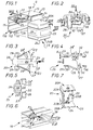
- the doubling device according to the invention comprises, on the one hand, a plate, by which it is able to overlap locally at the base of the trough to be fitted, and, on the other hand, means of fixing, and for example anchoring means, which are suitable for allowing its subjugation to this base.
- chute G whose base 10 has, externally, in section transverse, U-shaped profile, with a 11 midsole and two wings side 12.
- this base 10 is intended to be applied to any support, for example a wall, not shown.
- the chute G is assumed be relatively small in height and width, like chutes commonly called moldings, and its base 10 is devoid of any internal partition.
- the cover 13 is a profile, in material synthetic, produced by extrusion.
- this is, for example, a covering cover, that is to say a cover having, in addition to a wall front 14, two side wings 15, by which it is able to engage, the outside, on the base 10, over the entire height thereof.
- each of the lateral wings 12 of the base 10 forms, by itself, longitudinally, a groove 16 with turned concavity outwards, and that, on the other hand, each of the lateral wings 15 of the cover 13 comprises, longitudinally, projecting on its internal face, a rib 18 suitable for engaging in the groove 16 of the lateral wing 12 base 10.
- each of the side wings 12 of the base 10 forms, moreover, on its edge, to perfect the seat of the cover 13, a return angle 19, which, substantially parallel to the sole median 11, is directed inward.
- the base 10 can be called upon to receive, by fitting, any accessory.
- this accessory is a nozzle 20 to be attached to the end of the chute G, and therefore of the base 10, to transversely close this chute 10.
- This tip 20 a more complete description will be made subsequently, locally replaces the cover 13, while being able to possibly at least partially cover this one, and so it presents, overall, in addition to a transverse wall 22 capable of closing transversely the base 10, a front wall 23 and two side walls 24.
- such a device lining 25 is attached to at least one of the lateral wings 12 of the base 10, along the free edge of it.
- only one of these side wings 12 is thus equipped with such a doubling device 25.
- this doubling device 25 is arranged at the end of the lateral wing 12 on which it is reported.
- the doubling device 25 is capable of forming an extra thickness E both on the front, on the edge of the lateral wing 12 on which it is reported, only laterally, on at least one of the external faces and / or internal of this lateral wing 12.
- the accessory whose purpose it is to strengthen the holding is a nozzle intended to be attached from the outside to the chute G, and, more precisely, on its base 10, the additional thickness E sought must preferably intervene on the external face of the lateral wing 12 on which the doubling device 25 according to the invention is reported.
- the device lining 25 according to the invention is capable of forming an additional thickness E on one and the other of the external and internal faces of such a lateral wing 12, to be in measure of being able either to be reported on one or the other of the wings side 12 of base 10.
- the doubling device 25 according to the invention is in the general form of a suitable jumper coming to locally style the edge of any of these side wings 12.
- the doubling device 25 comprises, overall, on the one hand, a plate 26, by which it is able to locally superimpose on the base 10 of the chute G to equip, and, more precisely, on the right-angled return 19 of the lateral wing 12 concerned of this base 10, and, on the other hand, fixing means 27, which, according to arrangements described in more detail later, are specific to allow its subjection to this base 10.
- the plate 26 is substantially flat, and has a relatively elongated rectangular outline.
- the fixing means 27 are anchoring means capable of forcing into the base 10 of the chute G to be fitted.
- these fixing means 27 comprise at least an anchoring arm 28, which, connected to the plate 26 by a leg 29, is equipped with at least one claw 30, and which is generally deformable.
- the fixing means 27 comprise two anchoring arms 28, 28 ', which each intervene respectively on either side of the plate 26, and which have similar constitutions.
- the leg 29 extends generally transversely with respect to the plate 26, and perpendicular to it, while connecting to this plate 26 by a wide rounded.
- the two legs 29 that includes the doubling device 25 according to the invention are established opposite from each other, and they are about the same height.
- these legs 29 intervene at one of the ends of the plate 26.
- each of the anchoring arms 28, 28 'extends cantilevered from the free end of the leg 29 who wears it, and it is substantially square to it.
- the two anchoring arms 28, 28 ′ thus intervene substantially at the same level with respect to the plate 26, at a distance from the latter.
- the anchoring arms 28, 28 ′ initially diverge from one compared to each other from counters 29.
- each of the anchoring arms 28, 28 ' is articulated by a hinge zone 32 to the leg 29 which carries it.
- this hinge zone 32 can result from a simple deformation capacity of the material of the lining device 25 according to the invention.
- this hinge zone 32 extends substantially perpendicular to the plate 26, along the corresponding edge of the leg 29 concerned.
- the anchoring arms 28, 28 ' each have only one claw 30, and this is arranged at their free end.
- the claw 30 comes from a longitudinal sections of this anchor arm 28, 28 'forming locally a square return for this one.
- this is that of the slices longitudinal of such an anchor arm 28, 28 'which is closest to the platinum 26.
- the claw 30 extends in additionally generally perpendicular to such an anchoring arm 28, 28 ′, in direction of the plate 26, but in a plane substantially parallel to this one.
- the two claws 30 are offset relative to each other by anchor arms 28, 28 'to each other.
- It can be either a height offset or an offset longitudinal.
- the two claws 30 operate at the same level relative to the plate 26, at a distance of the latter, and their offset is therefore only longitudinal.
- the angle A 'relative to the shortest anchoring arm 28' is greater than the angle A relative to the longest anchoring arm 28.
- the two claws 30 From one anchoring arm 28, 28 'to the other, the two claws 30 have a similar, even identical, constitution.
- Each of them is blunted at its end, and comprises, transversely, at a distance therefrom, at least one barb 33.
- At least one of the longitudinal edges 34, 35 claws 30 is tapered, like the edge of a blade.
- edges longitudinal 34, 35 is thus tapered, and it is, in practice, the edge internal longitudinal 34, that is to say from the longitudinal edge which is the least distant from the corresponding leg 29.
- the outer longitudinal edge 35 i.e. the edge longitudinal furthest from the jamb 29, a, in this embodiment, a circular outline, being generally centered on this leg 29.
- the doubling device 25 further comprises, laterally, at a distance from the legs 29 carrying the anchoring arms 28, 28 ', two other legs 36.
- these legs 36 are established in look at each other, at the end of the plate 26 opposite to that where intervene the legs 29 carrying the anchoring arms 28, 28 ′.
- the device lining 25 comprises, transversely with respect to the plate 26, at one end thereof, and, more precisely, at that of its ends where the legs 29 carrying the anchoring arms intervene 28, 28 ', a locking tab 38.
- this stopper 38 extends over the entire width of the plate 26, in a way forming a extension, bent at right angles to it.
- this stopper 38 is less than that of the legs 29 carrying the arms anchor 28, 28 '.
- the doubling device 25 according to the invention comes in one piece from a metal blank, by cutting and folding this blank.
- this doubling device 25 is engaged, from the front, along arrow F1 of the Figure 6, on the edge of the side wing 12 of the base 10 of the chute G on which it should be reported.
- a clamp 39 is used to do this.
- the invention forms, locally, both on the edge of the lateral wing 12 concerned of this base 10 that on the external face thereof, an additional thickness E equal to the thickness E of its initial blank, that is to say the thickness E of its plate 26 and of its legs 29.
- This extra thickness E is sufficient to absorb any tolerances between the base 10 and the end piece 20.
- the end piece 20 is in two parts 20A, 20B, which each individually form its two walls side 24 and which jointly form its transverse wall 22 and its wall of facade 23, each comprising a transverse wall respectively 22A, 22B, closing, and a front wall 23A, 23B.
- each of these parts 20A, 20B comprises, in trihedron, a transverse wall 22A, 22B, a front wall 23A, 23B, and a side wall 24.
- the two parts 20A, 20B constituting the end piece 20 are mounted adjustable in position one by relative to the other, for possible adaptation of the end piece 20 to widths different for the base 10 to which it must be attached, and, therefore, for the chute G.
- the part 20A constitutes a female part in which slides sliding part 20B, which itself is a male part.
- the transverse wall 22A of this part 20A is lined internally, over a portion of its width from its edge free, by an internal wall 22'A, which forms with it a pocket 40 suitable for receiving the transverse wall 22B of the part 20B.
- the portion of the transverse wall 22A of the part 20A thus doubled by a internal wall 22'A is offset transversely outward relative to the current part of this transverse wall 22A, and it is the same for the front wall 23A.
- complementary fitting means of such a nature as to allow disengageable, a blocking in position of these two parts 20A, 20B, one by compared to each other.
- these blocking means include, in particular, a boss 42, which, projecting from the front wall 23B of part 20B, is able to cooperate in interlocking with one or the other two housings 43 provided in a hollow distance from each other on the wall of front panel 23A of part 20A.
- bosses 44 which, provided for projecting on the transverse wall 22B of the part 20B, are intended to cooperate in abutment with shoulders 45 provided in correspondence on the internal wall 22'A of part 20A.
- these shoulders 45 are formed by one of the sides of slots 46 locally affecting this internal wall 22'A.
- bosses 44 protrude from ribs 47 which themselves project from the transverse wall 22B of the part 20B for the reinforcement of this wall transverse 22B.
- the two parts 20A, 20B constituting the end piece 20 can occupy one with respect to the other one or the other of two stable positions well determined.
- each of the parts 20A, 20B constituting the end piece 20 comprises, projecting from the face internal of its side wall 24, at least one console 49 adapted to allow it latching in the groove 16 of the corresponding side wing 12 of the base 10 of the chute G concerned.
- part 20A For example, and as shown, only a console 49 is provided. on part 20A, while part 20B comprises, at a distance, one of the other, two consoles 49.
- each of the parts 20A, 20B constituting the endpiece 20 also carries, projecting from the face internal of its front wall 23A, 23B, at least one tab 50, for its blocking in rotation vis-à-vis the base 10, and therefore of the chute G.
- the scope of the invention is not limited to only case where the accessory to be brought to the chute to be fitted is a nozzle, but extends just as well to any other type of accessory.
- this accessory can just as easily be a support suitable for receiving any electrical equipment.
Landscapes
- Engineering & Computer Science (AREA)
- Architecture (AREA)
- Civil Engineering (AREA)
- Structural Engineering (AREA)
- Chutes (AREA)
- Joining Of Building Structures In Genera (AREA)
- Toys (AREA)
- Buckles (AREA)
Applications Claiming Priority (2)
| Application Number | Priority Date | Filing Date | Title |
|---|---|---|---|
| FR9616300A FR2758016B1 (fr) | 1996-12-31 | 1996-12-31 | Procede et dispositif pour affermir le maintien sur une goulotte d'un quelconque accessoire a rapporter par emboitement sur le socle de celle-ci |
| FR9616300 | 1996-12-31 |
Publications (2)
| Publication Number | Publication Date |
|---|---|
| EP0851551A1 true EP0851551A1 (de) | 1998-07-01 |
| EP0851551B1 EP0851551B1 (de) | 2004-08-25 |
Family
ID=9499372
Family Applications (1)
| Application Number | Title | Priority Date | Filing Date |
|---|---|---|---|
| EP97403169A Expired - Lifetime EP0851551B1 (de) | 1996-12-31 | 1997-12-29 | Verfahren und Vorrichtung zum Verbessern des Haltens eines Zubehörs mit Schnappbefestigung an einem Kabelrinnensockel |
Country Status (8)
| Country | Link |
|---|---|
| US (1) | US5981872A (de) |
| EP (1) | EP0851551B1 (de) |
| AU (1) | AU732736B2 (de) |
| BR (1) | BR9706344A (de) |
| DE (1) | DE69730403T2 (de) |
| ES (1) | ES2225943T3 (de) |
| FR (1) | FR2758016B1 (de) |
| PT (1) | PT851551E (de) |
Cited By (2)
| Publication number | Priority date | Publication date | Assignee | Title |
|---|---|---|---|---|
| US6641092B1 (en) * | 1999-10-15 | 2003-11-04 | Legrand | Support for devices, in particular for electrical devices, to be attached to the base section of trunking |
| FR2973596A1 (fr) * | 2011-03-31 | 2012-10-05 | Legrand France | Enveloppe allongee pour appareillages et/ou conducteurs electriques comportant un accessoire d'extremite |
Families Citing this family (9)
| Publication number | Priority date | Publication date | Assignee | Title |
|---|---|---|---|---|
| FR2786616B1 (fr) * | 1998-11-27 | 2001-02-16 | Legrand Sa | Support pour appareillage a disposer le long d'une goulotte avec auvent en plusieurs parties |
| FR2805673B1 (fr) * | 2000-02-24 | 2002-06-07 | Legrand Sa | Embout de fermeture d'une goulotte de cheminement de cables ou de conducteurs electriques |
| FR2806846B1 (fr) * | 2000-03-24 | 2002-06-21 | Legrand Sa | Boitier pour appareillage a disposer le long d'une goulotte, notamment pour appareillage electrique |
| FR2806848B1 (fr) * | 2000-03-24 | 2002-06-21 | Legrand Sa | Accessoire a rapporter sur un socle de goulotte de cheminement de conducteurs ou de cables electriques |
| US6484360B1 (en) * | 2000-04-27 | 2002-11-26 | Hubbell Incorporated | Self-securing raceway end cap |
| US6399883B1 (en) * | 2000-06-20 | 2002-06-04 | Thomas E. Lhota | Channel for low voltage electrical wiring |
| FR2820553B1 (fr) * | 2001-02-05 | 2003-07-25 | Legrand Sa | Accessoire pour goulotte et ensemble comprenant un tel accessoire et une goulotte dont le socle est specialement adapte audit accessoire |
| US7459633B2 (en) * | 2006-07-11 | 2008-12-02 | Vantage Point Products Corp. | Wire management system |
| US7544893B2 (en) * | 2007-07-25 | 2009-06-09 | Thomas & Betts International, Inc. | Extruded wire duct end cap |
Citations (2)
| Publication number | Priority date | Publication date | Assignee | Title |
|---|---|---|---|---|
| DE7701076U1 (de) * | 1977-01-15 | 1977-05-05 | Fa. Hermann Kleinhuis, 5880 Luedenscheid | Kabelkanal aus mehreren zusammenzusetzenden Abschnitten |
| DE8409752U1 (de) * | 1984-03-30 | 1984-08-23 | Tehalit Kunststoffwerk Gmbh, 6751 Heltersberg | Sockelleisten-Installationskanal |
Family Cites Families (7)
| Publication number | Priority date | Publication date | Assignee | Title |
|---|---|---|---|---|
| JPH0419938Y2 (de) * | 1987-12-17 | 1992-05-07 | ||
| FR2671849B1 (fr) * | 1991-01-23 | 1993-04-16 | Pgep | Dispositif de fermeture de l'extremite d'un profile. |
| US5523529A (en) * | 1991-03-26 | 1996-06-04 | Cable Ready, Inc. | Snap-fit protective molding assembly for electrical cables and entry tools therefor |
| FR2693849B1 (fr) * | 1992-07-17 | 1994-09-30 | Legrand Sa | Ensemble profilé composite de type goulotte ou analogue. |
| ES2077498B1 (es) * | 1993-07-05 | 1996-11-16 | Aparellaje Electrico Sa | Dispositivo adaptador de un mecanismo electrico a una canaleta. |
| US5442885A (en) * | 1994-04-15 | 1995-08-22 | A. O. Smith Corporation | Pre-assembly attachment system for a box-section frame member and method of assembling |
| US5747733A (en) * | 1997-03-03 | 1998-05-05 | Woods; Randall T. | Wiring duct entrance fitting enclosure |
-
1996
- 1996-12-31 FR FR9616300A patent/FR2758016B1/fr not_active Expired - Fee Related
-
1997
- 1997-12-29 PT PT97403169T patent/PT851551E/pt unknown
- 1997-12-29 ES ES97403169T patent/ES2225943T3/es not_active Expired - Lifetime
- 1997-12-29 EP EP97403169A patent/EP0851551B1/de not_active Expired - Lifetime
- 1997-12-29 DE DE69730403T patent/DE69730403T2/de not_active Expired - Fee Related
- 1997-12-30 BR BR9706344A patent/BR9706344A/pt not_active IP Right Cessation
- 1997-12-30 AU AU49313/97A patent/AU732736B2/en not_active Ceased
- 1997-12-30 US US09/000,831 patent/US5981872A/en not_active Expired - Lifetime
Patent Citations (2)
| Publication number | Priority date | Publication date | Assignee | Title |
|---|---|---|---|---|
| DE7701076U1 (de) * | 1977-01-15 | 1977-05-05 | Fa. Hermann Kleinhuis, 5880 Luedenscheid | Kabelkanal aus mehreren zusammenzusetzenden Abschnitten |
| DE8409752U1 (de) * | 1984-03-30 | 1984-08-23 | Tehalit Kunststoffwerk Gmbh, 6751 Heltersberg | Sockelleisten-Installationskanal |
Cited By (2)
| Publication number | Priority date | Publication date | Assignee | Title |
|---|---|---|---|---|
| US6641092B1 (en) * | 1999-10-15 | 2003-11-04 | Legrand | Support for devices, in particular for electrical devices, to be attached to the base section of trunking |
| FR2973596A1 (fr) * | 2011-03-31 | 2012-10-05 | Legrand France | Enveloppe allongee pour appareillages et/ou conducteurs electriques comportant un accessoire d'extremite |
Also Published As
| Publication number | Publication date |
|---|---|
| FR2758016A1 (fr) | 1998-07-03 |
| AU4931397A (en) | 1998-07-02 |
| US5981872A (en) | 1999-11-09 |
| EP0851551B1 (de) | 2004-08-25 |
| PT851551E (pt) | 2004-12-31 |
| BR9706344A (pt) | 1999-06-29 |
| DE69730403D1 (de) | 2004-09-30 |
| DE69730403T2 (de) | 2005-09-01 |
| FR2758016B1 (fr) | 1999-03-12 |
| ES2225943T3 (es) | 2005-03-16 |
| AU732736B2 (en) | 2001-04-26 |
Similar Documents
| Publication | Publication Date | Title |
|---|---|---|
| EP1263104A1 (de) | Winkelzubehörelement für Führungskanal | |
| FR2568978A1 (fr) | Dispositif pour raccorder les extremites de gaines en tole metallique et connecteur d'angle pour ce dispositif | |
| EP0851551B1 (de) | Verfahren und Vorrichtung zum Verbessern des Haltens eines Zubehörs mit Schnappbefestigung an einem Kabelrinnensockel | |
| CA2370080A1 (fr) | Accessoire pour goulotte et ensemble comprenant un tel accessoire et une goulotte dont le socle est specialement adapte audit accessoire | |
| FR2852157A1 (fr) | Dispositif de fixation d'un fil sur un element porteur muni d'au moins deux ouvertures et ensemble porteur pour chemin de cables comportant au moins un tel dispositif | |
| EP0734107B1 (de) | Winkelzubehörverbindungselement für Elektrokanal und Winkelzubehör dafür | |
| EP1042851B1 (de) | Winkelzubehörverbindungselement für kabelrinne mit einstellbarem winkel | |
| EP1128512B1 (de) | Endstück für den Führungskanal elektrischer Leiter oder Kabel | |
| FR2777129A1 (fr) | Goulotte de cablage et accessoire susceptible d'etre rapporte sur une telle goulotte de cablage | |
| EP0908992B1 (de) | Vorrichtung zur variablen Abdeckung von elektrischen kabelführungen | |
| FR2786618A1 (fr) | Support d'appareillage, notamment pour appareillage electrique, et boitier comportant un tel support d'appareillage | |
| FR2766905A1 (fr) | Profile a rainure(s) pour la mise en place d'au moins un accessoire | |
| EP0838885B1 (de) | Halteklammer für Kabelrinnen und zugehörige Kabelrinne | |
| EP1320163B1 (de) | Immobilisierungszubehör für ein elektrisches Installationsgerät mit Direktschnappverbindung in einem Kabelrinnesockel | |
| EP1498993A1 (de) | Zubehör für Kabelkanal mit automatischer Verriegelung | |
| EP0607083B1 (de) | Kabelrinnezusatz und Rinne ausgerustet mit einem solchem Zusatz | |
| EP1158634B1 (de) | Endstück für den Führungskanal elektrischer Leiter oder Kabel | |
| EP0755175B1 (de) | Verbindungsvorrichtung für Gerätegehäuse | |
| EP0923176B1 (de) | Greifhalter für Einbaudose und entsprechende Einbaudose | |
| EP1139537A1 (de) | Einbaudose für elektrisches Gerät zur Montage entlang einem Kabelkanal | |
| EP0908991B1 (de) | Zubehör für elektrischen Verkabelungsrohrleiter | |
| EP1246333A1 (de) | Endstück für einen Führungskanal | |
| EP0887903B1 (de) | Sockel für Kabelkanal mit einem V-förmigen Querschnitt, insbesondere Eckkanal oder Unterputzkanal | |
| FR2781097A1 (fr) | Boite d'encastrement pour cloison seche a patte(s) de serrage initialement d'un seul tenant, notamment pour appareillage electrique | |
| EP1617535A1 (de) | Flacheckverbindungs- oder Abzweigungseinrichtung passend für verschiedene Rinnenecken |
Legal Events
| Date | Code | Title | Description |
|---|---|---|---|
| PUAI | Public reference made under article 153(3) epc to a published international application that has entered the european phase |
Free format text: ORIGINAL CODE: 0009012 |
|
| AK | Designated contracting states |
Kind code of ref document: A1 Designated state(s): BE DE ES GB GR IT PT |
|
| AX | Request for extension of the european patent |
Free format text: AL;LT;LV;MK;RO;SI |
|
| 17P | Request for examination filed |
Effective date: 19980827 |
|
| AKX | Designation fees paid |
Free format text: BE DE ES GB GR IT PT |
|
| RBV | Designated contracting states (corrected) |
Designated state(s): BE DE ES GB GR IT PT |
|
| 17Q | First examination report despatched |
Effective date: 19991221 |
|
| GRAP | Despatch of communication of intention to grant a patent |
Free format text: ORIGINAL CODE: EPIDOSNIGR1 |
|
| RTI1 | Title (correction) |
Free format text: PROCESS AND DEVICE FOR INCREASING THE HOLD OF AN ACCESSORY TO BE SNAPPED IN A RACEWAY BASE |
|
| GRAS | Grant fee paid |
Free format text: ORIGINAL CODE: EPIDOSNIGR3 |
|
| GRAA | (expected) grant |
Free format text: ORIGINAL CODE: 0009210 |
|
| AK | Designated contracting states |
Kind code of ref document: B1 Designated state(s): BE DE ES GB GR IT PT |
|
| REG | Reference to a national code |
Ref country code: GB Ref legal event code: FG4D Free format text: NOT ENGLISH |
|
| REF | Corresponds to: |
Ref document number: 69730403 Country of ref document: DE Date of ref document: 20040930 Kind code of ref document: P |
|
| REG | Reference to a national code |
Ref country code: GR Ref legal event code: EP Ref document number: 20040403587 Country of ref document: GR |
|
| REG | Reference to a national code |
Ref country code: PT Ref legal event code: SC4A Free format text: AVAILABILITY OF NATIONAL TRANSLATION Effective date: 20041022 |
|
| GBT | Gb: translation of ep patent filed (gb section 77(6)(a)/1977) |
Effective date: 20041222 |
|
| REG | Reference to a national code |
Ref country code: ES Ref legal event code: FG2A Ref document number: 2225943 Country of ref document: ES Kind code of ref document: T3 |
|
| PLBE | No opposition filed within time limit |
Free format text: ORIGINAL CODE: 0009261 |
|
| STAA | Information on the status of an ep patent application or granted ep patent |
Free format text: STATUS: NO OPPOSITION FILED WITHIN TIME LIMIT |
|
| 26N | No opposition filed |
Effective date: 20050526 |
|
| PGFP | Annual fee paid to national office [announced via postgrant information from national office to epo] |
Ref country code: PT Payment date: 20061117 Year of fee payment: 10 |
|
| PGFP | Annual fee paid to national office [announced via postgrant information from national office to epo] |
Ref country code: GR Payment date: 20061129 Year of fee payment: 10 |
|
| PGFP | Annual fee paid to national office [announced via postgrant information from national office to epo] |
Ref country code: DE Payment date: 20061211 Year of fee payment: 10 |
|
| PGFP | Annual fee paid to national office [announced via postgrant information from national office to epo] |
Ref country code: ES Payment date: 20061214 Year of fee payment: 10 |
|
| PGFP | Annual fee paid to national office [announced via postgrant information from national office to epo] |
Ref country code: GB Payment date: 20061218 Year of fee payment: 10 |
|
| PGFP | Annual fee paid to national office [announced via postgrant information from national office to epo] |
Ref country code: IT Payment date: 20061231 Year of fee payment: 10 |
|
| PGFP | Annual fee paid to national office [announced via postgrant information from national office to epo] |
Ref country code: BE Payment date: 20070112 Year of fee payment: 10 |
|
| BERE | Be: lapsed |
Owner name: *LEGRAND S.N.C. Effective date: 20071231 Owner name: *LEGRAND Effective date: 20071231 |
|
| REG | Reference to a national code |
Ref country code: PT Ref legal event code: MM4A Free format text: LAPSE DUE TO NON-PAYMENT OF FEES Effective date: 20080630 |
|
| GBPC | Gb: european patent ceased through non-payment of renewal fee |
Effective date: 20071229 |
|
| PG25 | Lapsed in a contracting state [announced via postgrant information from national office to epo] |
Ref country code: PT Free format text: LAPSE BECAUSE OF NON-PAYMENT OF DUE FEES Effective date: 20080630 Ref country code: BE Free format text: LAPSE BECAUSE OF NON-PAYMENT OF DUE FEES Effective date: 20071231 |
|
| PG25 | Lapsed in a contracting state [announced via postgrant information from national office to epo] |
Ref country code: DE Free format text: LAPSE BECAUSE OF NON-PAYMENT OF DUE FEES Effective date: 20080701 |
|
| PG25 | Lapsed in a contracting state [announced via postgrant information from national office to epo] |
Ref country code: GB Free format text: LAPSE BECAUSE OF NON-PAYMENT OF DUE FEES Effective date: 20071229 |
|
| REG | Reference to a national code |
Ref country code: ES Ref legal event code: FD2A Effective date: 20071231 |
|
| PG25 | Lapsed in a contracting state [announced via postgrant information from national office to epo] |
Ref country code: ES Free format text: LAPSE BECAUSE OF NON-PAYMENT OF DUE FEES Effective date: 20071231 |
|
| PG25 | Lapsed in a contracting state [announced via postgrant information from national office to epo] |
Ref country code: GR Free format text: LAPSE BECAUSE OF NON-PAYMENT OF DUE FEES Effective date: 20080702 |
|
| PG25 | Lapsed in a contracting state [announced via postgrant information from national office to epo] |
Ref country code: IT Free format text: LAPSE BECAUSE OF NON-PAYMENT OF DUE FEES Effective date: 20071229 |