EP0851559B1 - Elektrische Maschine synchroner Bauart - Google Patents
Elektrische Maschine synchroner Bauart Download PDFInfo
- Publication number
- EP0851559B1 EP0851559B1 EP97403170A EP97403170A EP0851559B1 EP 0851559 B1 EP0851559 B1 EP 0851559B1 EP 97403170 A EP97403170 A EP 97403170A EP 97403170 A EP97403170 A EP 97403170A EP 0851559 B1 EP0851559 B1 EP 0851559B1
- Authority
- EP
- European Patent Office
- Prior art keywords
- stator
- notches
- rotor
- stages
- synchronous machine
- Prior art date
- Legal status (The legal status is an assumption and is not a legal conclusion. Google has not performed a legal analysis and makes no representation as to the accuracy of the status listed.)
- Expired - Lifetime
Links
Images


Classifications
-
- H—ELECTRICITY
- H02—GENERATION; CONVERSION OR DISTRIBUTION OF ELECTRIC POWER
- H02K—DYNAMO-ELECTRIC MACHINES
- H02K19/00—Synchronous motors or generators
- H02K19/02—Synchronous motors
- H02K19/10—Synchronous motors for multi-phase current
- H02K19/103—Motors having windings on the stator and a variable reluctance soft-iron rotor without windings
-
- H—ELECTRICITY
- H02—GENERATION; CONVERSION OR DISTRIBUTION OF ELECTRIC POWER
- H02K—DYNAMO-ELECTRIC MACHINES
- H02K19/00—Synchronous motors or generators
- H02K19/02—Synchronous motors
- H02K19/04—Synchronous motors for single-phase current
- H02K19/06—Motors having windings on the stator and a variable-reluctance soft-iron rotor without windings, e.g. inductor motors
-
- H—ELECTRICITY
- H02—GENERATION; CONVERSION OR DISTRIBUTION OF ELECTRIC POWER
- H02K—DYNAMO-ELECTRIC MACHINES
- H02K19/00—Synchronous motors or generators
- H02K19/16—Synchronous generators
- H02K19/18—Synchronous generators having windings each turn of which co-operates only with poles of one polarity, e.g. homopolar generators
- H02K19/20—Synchronous generators having windings each turn of which co-operates only with poles of one polarity, e.g. homopolar generators with variable-reluctance soft-iron rotors without winding
-
- H—ELECTRICITY
- H02—GENERATION; CONVERSION OR DISTRIBUTION OF ELECTRIC POWER
- H02K—DYNAMO-ELECTRIC MACHINES
- H02K21/00—Synchronous motors having permanent magnets; Synchronous generators having permanent magnets
- H02K21/38—Synchronous motors having permanent magnets; Synchronous generators having permanent magnets with rotating flux distributors, and armatures and magnets both stationary
- H02K21/44—Synchronous motors having permanent magnets; Synchronous generators having permanent magnets with rotating flux distributors, and armatures and magnets both stationary with armature windings wound upon the magnets
Definitions
- the present invention relates to machines electric synchronous type.
- the synchronous machine proposed by the invention can be used both as a generator and as a motor electric.
- the rotor of the synchronous machine is the most balanced possible and has no windings and permanent magnets.
- Document FR-2 075 995 already discloses a electric machine comprising a rotor and a stator which each presents a succession of notches spread over their circumference, the rotor being a stack of sheets free of conductive windings and magnets permanent, the stator having means of magnetization which define at least one pair of poles on it, these magnetization means comprising at least one inductor winding received in stator notches, the stator notches also receiving at least one armature winding.
- the invention proposes a machine electric device according to claim 1.
- the single-phase synchronous machine illustrated on the Figures 1 and 2 comprises a rotor 1 and a stator 2.
- the rotor 1 is constituted by a stack of sheets, which has a succession of notches 3 regularly distributed around its circumference.
- rotor 1 Unlike the rotors of synchronous machines conventional single-phase, rotor 1 has no magnet capable of defining poles and its notches 3 receive no conductive winding.
- the stator 2 comprises a carcass constituted by a stack of sheets. This carcass has a plurality of notches 4, which are distributed over its inner circumference and which receive at least one induced winding 5 and an inductive winding 6.
- the number of notches 4 is double the number notches 3.
- Windings 5 and 6 are wound on the notches 4 not in a loop, but according to a wavy configuration, the induced winding 5 being angularly offset by a notch relative to the inductor winding 6 and extending into notches 4 centered on the north and south poles defined by said field winding 6.
- inductor replace winding 6 with permanent magnets.
- solutions with inductor winding are preferred given that they make it possible to vary the field between the poles. In a manner known per se, this variation of the field is used in generator mode to regulate the amplitude of the voltage across the armature.
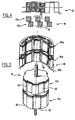
- FIGS. 4 and 5 illustrate a mode of possible realization for a conforming two-phase machine to the invention.
- the rotor and the stator referenced respectively by 11 and 12, each have, along the direction of the axis of rotation, two superimposed floors.
- the two stages of the rotor 11 - referenced by 11a and 11b - are respectively opposite the two stages - referenced by 12a and 12b - from stator 12.
- the two stages 11a, 11b each have notches 13 which are regularly distributed over the circumference of the rotor 11, being angularly offset from one floor to another by half the length between two notches.
- the two stages 12a and 12b of the stator 12 have notches 14 which extend in line with the from one another from one floor to another.
- An inductor winding 16 is distributed in these notches 14 in a wavy configuration, being wound on the entire height of the stator 12, the turns of said winding extending in the notches 14 of the stages 12a and 12b from one end to the other of the stator.
- an armature winding 15a is wound in the notches 14 of the stage 12a, while a armature winding 15b is wound in the notches 14 of floor 12b.
- These windings 15a, 15b are both wound in a wavy configuration, so homologous, i.e. without angular offset one by compared to each other
- stator notches which are offset from one stage to the other, the notches on either of the two floors of the rotor being superimposed without angular offset of one floor to another.
- the configuration illustrated in Figures 4 and 5 has the advantage of allowing to use a common winding to constitute the inductor of either of the two stages.
- an electric machine with n phases comprises a stator and a rotor which have each n stages of notches, the stator or rotor being offset from one stage to another by the width angular between two notches divided by n.
- FIG. 6 an embodiment of a three-phase machine in that meaning.
- This machine comprises a rotor 21 and a stator 22.
- the rotor 21 and the stator 22 each have three stages - referenced by 21a to 21c for rotor 21 and by 22a to 22c for stator 22.
- the notches 23 of two successive stages of the rotor 21 are shifted from one floor to another by the width between two notches divided by 3.
- the notches 24 of different stages of the stator are arranged in the extension of each other.
- the stator has for each stage 22a to 22c a armature winding 25a to 25c wound around its notches 24.
- An inductor winding 26 is wound around the notches 24 over the entire height of the stator 22.
Landscapes
- Engineering & Computer Science (AREA)
- Power Engineering (AREA)
- Iron Core Of Rotating Electric Machines (AREA)
- Synchronous Machinery (AREA)
- Permanent Magnet Type Synchronous Machine (AREA)
- Windings For Motors And Generators (AREA)
Claims (9)
- Elektrische Maschine mit einem Rotor und einem Stator, die jeweils eine Abfolge von auf ihrem Umfang verteilten Nuten aufweisen, wobei der Rotor (1, 11, 21) ein Blechpaket ohne leitende Wicklungen und Permanentmagneten ist, während der Stator (2, 12, 22) Magnetisierungsmittel (6, 16, 26) aufweist, die darauf wenigstens ein Polpaar definieren, wobei diese Magnetisierungsmittel (6, 16, 26) wenigstens eine in Nuten (4, 14, 24) des Stators (2, 12, 22) aufgenommene Feldwicklung umfassen und wobei die Nuten des Stators außerdem wenigstens eine Ankerwicklung (5, 15, 25) aufnehmen, wobei die besagte Maschine dadurch gekennzeichnet ist, daß sie eine Synchronmaschine ist und daß die Anzahl der Nuten auf einem Umfang des Stators doppelt so groß ist wie die Anzahl der Nuten des Rotors, wobei die Feldwicklung(en) und Ankerwicklung(en) (5, 6; 15, 16; 25, 26) auf den Nuten des Stators nach einer gewellten Gestaltung gewickelt sind, wobei eine Ankerwicklung (5, 15, 25) im Verhältnis zur Feldwicklung (6, 16, 26) winklig um eine Nut versetzt ist und sich in Nuten (4, 14, 24) erstreckt, die auf durch die besagte Feldwicklung (6, 16, 26) definierte Nord- und Südpole zentriert sind.
- Synchronmaschine nach Anspruch 1, dadurch gekennzeichnet, daß der Stator (12, 22) und der Rotor (11, 21) mehrere Stufen aufweisen, wobei jede der Stufen des Stators eine Ankerwicklung entsprechend einer Phase der Maschine aufnimmt.
- Synchronmaschine nach Anspruch 2, dadurch gekennzeichnet, daß die Nuten (13, 23) der verschiedenen Stufen des Rotors, von einer Stufe zur anderen, winklig um die Breite zwischen zwei Nuten, geteilt durch die Anzahl der Stufen, zueinander versetzt sind.
- Synchronmaschine nach Anspruch 3, dadurch gekennzeichnet, daß die Nuten (14, 24) der verschiedenen Stufen des Stators auf diesem ohne Winkelversatz von einer Stufe zur anderen verteilt sind, wobei der besagte Stator (12, 22) eine Feldwicklung (16, 26) aufweist, die auf seiner gesamten Höhe gewickelt und seinen verschiedenen Stufen gemeinsam ist.
- Synchronmaschine nach einem der Ansprüche 3 und 4, dadurch gekennzeichnet, daß die Ankerwicklungen (15a, 15b) der verschiedenen Stufen homolog auf den Nuten des Stators, ohne Winkelversatz von einer Stufe zur anderen, gewickelt sind.
- Dreiphasen-Synchronmaschine nach einem der vorangehenden Ansprüche.
- Synchronmaschine, die dazu bestimmt ist, einerseits als Generator und andererseits als Elektromotor verwendet zu werden, dadurch gekennzeichnet, daß sie in der Bauart nach einem der vorangehenden Ansprüche ausgeführt ist.
- Synchronmaschine für Kraftfahrzeuge, die dazu bestimmt ist, einerseits als Wechselstromgenerator und andererseits als Elektromotor des Anlassers verwendet zu werden, dadurch gekennzeichnet, daß sie in der Bauart nach einem der Ansprüche 1 bis 6 ausgeführt ist.
- Synchronmaschine nach Anspruch 8, dadurch gekennzeichnet, daß ihr Rotor an der Welle des Verbrennungsmotors gelagert ist.
Applications Claiming Priority (2)
| Application Number | Priority Date | Filing Date | Title |
|---|---|---|---|
| FR9616282A FR2758018B1 (fr) | 1996-12-31 | 1996-12-31 | Machine electrique de type synchrone |
| FR9616282 | 1996-12-31 |
Publications (2)
| Publication Number | Publication Date |
|---|---|
| EP0851559A1 EP0851559A1 (de) | 1998-07-01 |
| EP0851559B1 true EP0851559B1 (de) | 2003-04-16 |
Family
ID=9499357
Family Applications (1)
| Application Number | Title | Priority Date | Filing Date |
|---|---|---|---|
| EP97403170A Expired - Lifetime EP0851559B1 (de) | 1996-12-31 | 1997-12-29 | Elektrische Maschine synchroner Bauart |
Country Status (5)
| Country | Link |
|---|---|
| US (1) | US5936325A (de) |
| EP (1) | EP0851559B1 (de) |
| DE (1) | DE69720945T2 (de) |
| ES (1) | ES2197322T3 (de) |
| FR (1) | FR2758018B1 (de) |
Families Citing this family (32)
| Publication number | Priority date | Publication date | Assignee | Title |
|---|---|---|---|---|
| US6198194B1 (en) | 1999-09-17 | 2001-03-06 | Trw Inc. | Segmented rotor for an electric machine |
| JP3842001B2 (ja) * | 2000-02-16 | 2006-11-08 | 三菱電機株式会社 | 車両用交流発電機 |
| RU2176844C2 (ru) * | 2000-12-27 | 2001-12-10 | Открытое акционерное общество "МЭЛ" | Двигатель |
| US6724110B2 (en) * | 2001-12-31 | 2004-04-20 | Visteon Global Technologies, Inc. | Reluctance generator for an eddy current braking system |
| US6727629B1 (en) * | 2002-06-04 | 2004-04-27 | Wavecrest Laboratories, Llc | Rotary electric motor having a plurality of shifted stator poles and/or rotor poles |
| US6946771B2 (en) * | 2002-07-10 | 2005-09-20 | Quebec Metal Powders Limited | Polyphase claw pole structures for an electrical machine |
| US7119467B2 (en) | 2003-03-21 | 2006-10-10 | Pratt & Whitney Canada Corp. | Current limiting means for a generator |
| US6920023B2 (en) * | 2003-03-21 | 2005-07-19 | Pratt & Whitney Canada Corp. | Current limiting means for a generator |
| US6965183B2 (en) * | 2003-05-27 | 2005-11-15 | Pratt & Whitney Canada Corp. | Architecture for electric machine |
| US7583063B2 (en) | 2003-05-27 | 2009-09-01 | Pratt & Whitney Canada Corp. | Architecture for electric machine |
| US7262539B2 (en) * | 2004-11-26 | 2007-08-28 | Pratt & Whitney Canada Corp. | Saturation control of electric machine |
| US7545056B2 (en) * | 2003-05-27 | 2009-06-09 | Pratt & Whitney Canada Corp. | Saturation control of electric machine |
| US7253548B2 (en) * | 2003-06-16 | 2007-08-07 | Pratt & Whitney Canada Corp. | Method and apparatus for controlling an electric machine |
| FR2876231B1 (fr) * | 2004-05-06 | 2006-12-22 | Gerard Koehler | Machine dynamo-electrique tournante a reluctance variable a globalisation des circuits magnetiques, electriques et de polarisation et son procede de fabrication |
| JP5046536B2 (ja) * | 2006-03-15 | 2012-10-10 | 幸男 高橋 | リニアドライブ走行システム及び自動車 |
| US7288923B1 (en) | 2006-04-21 | 2007-10-30 | Pratt & Whitney Canada Corp. | Voltage-limited electric machine |
| US7443642B2 (en) * | 2006-05-26 | 2008-10-28 | Pratt & Whitney Canada Corp. | Electric motor control |
| US20080197740A1 (en) * | 2007-02-15 | 2008-08-21 | Hughes William L | Modular motor or alternator assembly |
| JP4569839B2 (ja) * | 2007-05-25 | 2010-10-27 | 株式会社デンソー | 交流モータ |
| WO2012119317A1 (zh) * | 2011-03-10 | 2012-09-13 | 浙江博望科技发展有限公司 | 铁氧体三段式三相永磁电机 |
| CN103222155B (zh) * | 2011-03-10 | 2016-06-01 | 浙江博望科技发展有限公司 | 铁氧体三段式三相永磁电机 |
| TWI655654B (zh) | 2011-06-30 | 2019-04-01 | 皮爾西蒙科技公司 | 用於製造結構化之材料之系統及方法 |
| US10022789B2 (en) | 2011-06-30 | 2018-07-17 | Persimmon Technologies Corporation | System and method for making a structured magnetic material with integrated particle insulation |
| US10476324B2 (en) | 2012-07-06 | 2019-11-12 | Persimmon Technologies Corporation | Hybrid field electric motor |
| US9502952B2 (en) | 2012-10-12 | 2016-11-22 | Persimmon Technologies, Corp. | Hybrid motor |
| US10570494B2 (en) | 2013-09-30 | 2020-02-25 | Persimmon Technologies Corporation | Structures utilizing a structured magnetic material and methods for making |
| JP6959735B2 (ja) | 2013-09-30 | 2021-11-05 | パーシモン テクノロジーズ コーポレイションPersimmon Technologies, Corp. | 構造化磁性材料を利用する構造物と方法 |
| CN104362821A (zh) * | 2014-09-29 | 2015-02-18 | 王国仁 | 多级外转子开关磁阻电机 |
| CN104300752B (zh) * | 2014-09-29 | 2018-04-17 | 王国仁 | 多级内转子开关磁阻电机 |
| KR101964069B1 (ko) * | 2017-12-20 | 2019-04-02 | (주)바롬코리아 | 구동토크가 개선된 다단발전기 |
| CN110380533B (zh) * | 2019-06-21 | 2025-04-04 | 科力尔电机集团股份有限公司 | 一种电机及包括该电机的设备 |
| WO2023171103A1 (ja) * | 2022-03-09 | 2023-09-14 | 株式会社プロテリアル | 回転電機 |
Family Cites Families (10)
| Publication number | Priority date | Publication date | Assignee | Title |
|---|---|---|---|---|
| SE358779B (de) * | 1970-01-08 | 1973-08-06 | Asea Ab | |
| US4450396A (en) * | 1980-09-23 | 1984-05-22 | Massachusetts Institute Of Technology | Electrically controlled synchronous machine |
| SE431275B (sv) * | 1983-04-07 | 1984-01-23 | Vnii Elektromash | Elektrisk maskin |
| HU188458B (en) * | 1983-06-06 | 1986-04-28 | Villamosipari Kutato Intezet,Hu | Singlephase or multiphase heteropolar or homopolar reluctance generator |
| DE58904848D1 (de) * | 1989-04-27 | 1993-08-05 | Siemens Ag | Heteropolar erregte synchronmaschine. |
| SE467422B (sv) * | 1990-04-23 | 1992-07-13 | Volvo Ab | Anordning foer att saekerstaella start av en foerbraenningsmotor |
| US5365137A (en) * | 1990-11-01 | 1994-11-15 | Dynamic Systems International Inc. | Electric motor |
| US5485046A (en) * | 1992-02-20 | 1996-01-16 | Dana Corporation | Variable reluctance electric motor |
| US5304882A (en) * | 1992-05-11 | 1994-04-19 | Electric Power Research Institute, Inc. | Variable reluctance motors with permanent magnet excitation |
| JPH06351206A (ja) * | 1993-04-14 | 1994-12-22 | Meidensha Corp | ハイブリッド励磁形永久磁石同期回転機 |
-
1996
- 1996-12-31 FR FR9616282A patent/FR2758018B1/fr not_active Expired - Fee Related
-
1997
- 1997-12-29 DE DE69720945T patent/DE69720945T2/de not_active Expired - Lifetime
- 1997-12-29 EP EP97403170A patent/EP0851559B1/de not_active Expired - Lifetime
- 1997-12-29 ES ES97403170T patent/ES2197322T3/es not_active Expired - Lifetime
- 1997-12-29 US US08/998,788 patent/US5936325A/en not_active Expired - Lifetime
Also Published As
| Publication number | Publication date |
|---|---|
| US5936325A (en) | 1999-08-10 |
| FR2758018A1 (fr) | 1998-07-03 |
| ES2197322T3 (es) | 2004-01-01 |
| DE69720945D1 (de) | 2003-05-22 |
| FR2758018B1 (fr) | 2006-06-16 |
| EP0851559A1 (de) | 1998-07-01 |
| DE69720945T2 (de) | 2003-12-18 |
Similar Documents
| Publication | Publication Date | Title |
|---|---|---|
| EP0851559A1 (de) | Elektrische Maschine synchroner Bauart | |
| EP0172977B1 (de) | Elektrischer Motor | |
| FR2852461A1 (fr) | Stator pour machine dynamo-electriques | |
| WO1998047216A1 (fr) | Machine polyphasee sans balais, notamment alternateur de vehicule automobile | |
| EP0795229A1 (de) | Burstenlosen mehrphasigen wechselstrommotor | |
| WO1983002043A1 (fr) | Machine electrique tournante formant notamment variateur de vitesse ou convertisseur de couple | |
| FR2748358A1 (fr) | Machine electrique comprenant un stator et un rotor a poles divises en une pluralite de sections longitudinales | |
| EP3602755A1 (de) | Elektrische drehmaschine mit verbesserter anordnung | |
| EP1661230A1 (de) | Elektrische polyphasen-drehmaschine, wie zum beispiel eine lichtmaschine oder ein alterno-anlasser insbesondere für ein kraftfahrzeug | |
| WO2015193562A1 (fr) | Moteur synchrone électromagnétique à flux magnétiques combinés axial et radial | |
| FR2618616A1 (fr) | Machine electrique a couple d'entrainement et/ou de positionnement eleve | |
| FR3051295B1 (fr) | Machine electrique tournante a puissance augmentee | |
| WO2008043926A1 (fr) | Rotor a griffes muni d'elements ferromagnetiques interpolaires de largeur optimisee et machine tournante equipee d'un tel rotor | |
| FR2811155A1 (fr) | Machine asynchrone comportant quatre poles ou plus | |
| WO2020165252A1 (fr) | Machine électrique synchrone polyphasée à commutateur mécanique | |
| EP3763018B1 (de) | Drehende elektrische maschine mit bruchlochwicklung | |
| FR3086118A1 (fr) | Machine electrique tournante munie d'un rotor a masse reduite | |
| WO2017093634A1 (fr) | Rotor a griffes de machine electrique tournante a performances magnetiques ameliorees | |
| FR3011142A1 (fr) | Stator ameliore pour machine a aimants permanents a commutation de flux | |
| FR2485287A1 (fr) | Machine electrique tournante a courant continu ou a courant alternatif redresse | |
| WO2015193563A1 (fr) | Moteur synchrone électromagnétique à flux magnétiques combinés axial et radial avec double excitation | |
| FR3025059A1 (fr) | Moteur ou generatrice synchrone electromagnetique a plusieurs entrefers et flux magnetique diagonal | |
| FR2545292A1 (fr) | Petit moteur electrique synchrone reversible a demarrage automatique | |
| FR2529724A1 (fr) | Machine tournante electrique | |
| FR3112251A1 (fr) | Machine électrique synchrone équipée d’un commutateur mécanique |
Legal Events
| Date | Code | Title | Description |
|---|---|---|---|
| PUAI | Public reference made under article 153(3) epc to a published international application that has entered the european phase |
Free format text: ORIGINAL CODE: 0009012 |
|
| AK | Designated contracting states |
Kind code of ref document: A1 Designated state(s): DE ES GB IT |
|
| AX | Request for extension of the european patent |
Free format text: AL;LT;LV;MK;RO;SI |
|
| 17P | Request for examination filed |
Effective date: 19981230 |
|
| AKX | Designation fees paid |
Free format text: DE ES GB IT |
|
| RBV | Designated contracting states (corrected) |
Designated state(s): DE ES GB IT |
|
| 17Q | First examination report despatched |
Effective date: 20010223 |
|
| GRAH | Despatch of communication of intention to grant a patent |
Free format text: ORIGINAL CODE: EPIDOS IGRA |
|
| GRAH | Despatch of communication of intention to grant a patent |
Free format text: ORIGINAL CODE: EPIDOS IGRA |
|
| GRAA | (expected) grant |
Free format text: ORIGINAL CODE: 0009210 |
|
| AK | Designated contracting states |
Designated state(s): DE ES GB IT |
|
| REG | Reference to a national code |
Ref country code: GB Ref legal event code: FG4D Free format text: NOT ENGLISH |
|
| REF | Corresponds to: |
Ref document number: 69720945 Country of ref document: DE Date of ref document: 20030522 Kind code of ref document: P |
|
| GBT | Gb: translation of ep patent filed (gb section 77(6)(a)/1977) | ||
| REG | Reference to a national code |
Ref country code: ES Ref legal event code: FG2A Ref document number: 2197322 Country of ref document: ES Kind code of ref document: T3 |
|
| PLBE | No opposition filed within time limit |
Free format text: ORIGINAL CODE: 0009261 |
|
| STAA | Information on the status of an ep patent application or granted ep patent |
Free format text: STATUS: NO OPPOSITION FILED WITHIN TIME LIMIT |
|
| 26N | No opposition filed |
Effective date: 20040119 |
|
| PGFP | Annual fee paid to national office [announced via postgrant information from national office to epo] |
Ref country code: ES Payment date: 20121219 Year of fee payment: 16 Ref country code: IT Payment date: 20121217 Year of fee payment: 16 Ref country code: GB Payment date: 20121219 Year of fee payment: 16 |
|
| GBPC | Gb: european patent ceased through non-payment of renewal fee |
Effective date: 20131229 |
|
| PG25 | Lapsed in a contracting state [announced via postgrant information from national office to epo] |
Ref country code: GB Free format text: LAPSE BECAUSE OF NON-PAYMENT OF DUE FEES Effective date: 20131229 |
|
| REG | Reference to a national code |
Ref country code: ES Ref legal event code: FD2A Effective date: 20150327 |
|
| PG25 | Lapsed in a contracting state [announced via postgrant information from national office to epo] |
Ref country code: ES Free format text: LAPSE BECAUSE OF NON-PAYMENT OF DUE FEES Effective date: 20131230 |
|
| PGFP | Annual fee paid to national office [announced via postgrant information from national office to epo] |
Ref country code: DE Payment date: 20141211 Year of fee payment: 18 |
|
| PG25 | Lapsed in a contracting state [announced via postgrant information from national office to epo] |
Ref country code: IT Free format text: LAPSE BECAUSE OF NON-PAYMENT OF DUE FEES Effective date: 20131231 |
|
| PG25 | Lapsed in a contracting state [announced via postgrant information from national office to epo] |
Ref country code: IT Free format text: LAPSE BECAUSE OF NON-PAYMENT OF DUE FEES Effective date: 20131229 |
|
| REG | Reference to a national code |
Ref country code: DE Ref legal event code: R119 Ref document number: 69720945 Country of ref document: DE |
|
| PG25 | Lapsed in a contracting state [announced via postgrant information from national office to epo] |
Ref country code: DE Free format text: LAPSE BECAUSE OF NON-PAYMENT OF DUE FEES Effective date: 20160701 |