EP0851606A2 - Wiederholer für Telekommunikationssanordnung - Google Patents
Wiederholer für Telekommunikationssanordnung Download PDFInfo
- Publication number
- EP0851606A2 EP0851606A2 EP97310010A EP97310010A EP0851606A2 EP 0851606 A2 EP0851606 A2 EP 0851606A2 EP 97310010 A EP97310010 A EP 97310010A EP 97310010 A EP97310010 A EP 97310010A EP 0851606 A2 EP0851606 A2 EP 0851606A2
- Authority
- EP
- European Patent Office
- Prior art keywords
- signal
- phase
- amplitude
- input signal
- repeater
- Prior art date
- Legal status (The legal status is an assumption and is not a legal conclusion. Google has not performed a legal analysis and makes no representation as to the accuracy of the status listed.)
- Granted
Links
Images


Classifications
-
- H—ELECTRICITY
- H04—ELECTRIC COMMUNICATION TECHNIQUE
- H04B—TRANSMISSION
- H04B7/00—Radio transmission systems, i.e. using radiation field
- H04B7/14—Relay systems
- H04B7/15—Active relay systems
- H04B7/155—Ground-based stations
- H04B7/15564—Relay station antennae loop interference reduction
- H04B7/15578—Relay station antennae loop interference reduction by gain adjustment
-
- H—ELECTRICITY
- H04—ELECTRIC COMMUNICATION TECHNIQUE
- H04B—TRANSMISSION
- H04B1/00—Details of transmission systems, not covered by a single one of groups H04B3/00 - H04B13/00; Details of transmission systems not characterised by the medium used for transmission
- H04B1/38—Transceivers, i.e. devices in which transmitter and receiver form a structural unit and in which at least one part is used for functions of transmitting and receiving
- H04B1/40—Circuits
- H04B1/50—Circuits using different frequencies for the two directions of communication
- H04B1/52—Hybrid arrangements, i.e. arrangements for transition from single-path two-direction transmission to single-direction transmission on each of two paths or vice versa
- H04B1/525—Hybrid arrangements, i.e. arrangements for transition from single-path two-direction transmission to single-direction transmission on each of two paths or vice versa with means for reducing leakage of transmitter signal into the receiver
-
- H—ELECTRICITY
- H04—ELECTRIC COMMUNICATION TECHNIQUE
- H04B—TRANSMISSION
- H04B7/00—Radio transmission systems, i.e. using radiation field
- H04B7/24—Radio transmission systems, i.e. using radiation field for communication between two or more posts
- H04B7/26—Radio transmission systems, i.e. using radiation field for communication between two or more posts at least one of which is mobile
- H04B7/2603—Arrangements for wireless physical layer control
- H04B7/2606—Arrangements for base station coverage control, e.g. by using relays in tunnels
Definitions
- This invention relates to telecommunications transmission systems and in particular to a repeater which may be used in a wireless transmission system.
- CDMA Code Division Multiple Access
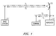
- FIG. 1 A system employing a repeater is illustrated in FIG. 1.
- the repeater, 10 will receive signals from the base station, 11, at a frequency, f 1 , and transmit signals to the station at a frequency, f 2 , using a highly directional dish antenna, 13.
- the repeater, 10, will also transmit to the wireless terminal, 12, at the frequency f 1 and receive at the frequency f 2 using an omni or directional antenna, 14. Since the links between the repeater and base station and between the repeater and terminal are at the same set of frequencies, interference can be a significant problem.
- the invention is a repeater including means for receiving input signals and means for transmitting output signals.
- the repeater further includes means for sampling an output signal and for feeding back the sampled output signal so as to subtract any leakage signal from an input signal.
- Switching means turns off an output signal for a first designated time interval.
- Means are provided for sampling an input signal during the first time interval and determining the amplitude and phase of the signal. The amplitude and phase of the feedback signal are then adjusted based on the amplitude and phase of the input signal received during the designated time interval.
- FIG. 1 illustrates a system, described above, which can use a repeater in accordance with the invention.
- FIG. 2 illustrates a repeater in accordance with a first embodiment.
- the dish antenna, 13, which communicates with the base station, 11 of FIG. 1, is connected to a duplexer, 21.
- the input signal from the base station is connected from the duplexer by means of a coaxial cable, 22, to a low noise amplifier, 23.
- the output of the amplifier, 23, is connected to a standard RF switch, 24.
- the output of the switch, 24, is connected to a transmitter amplifier, 25, whose output is connected by means of a coaxial cable, 26, to another duplexer, 27.
- the output of the duplexer, 27, is transmitted by means of the antenna, 14, to the wireless terminal, 12 of FIG. 1.
- a directional coupler, 30, is used in order to pick up or sample a portion of the transmitted signal from amplifier, 25.
- the directional coupler, 30, is coupled to standard circuitry, 31, which adjusts the phase and amplitude (gain) of the sampled signal in response to circuitry to be described.
- the output of the gain and phase circuitry, 31, is coupled to a delay line, 32, whose output is coupled to a directional coupler, 33, at the input to the low noise amplifier, 23.
- the low level detector also has an output connected to the RE switch, 24, and an output connected to a voltage controlled oscillator (VCO), 40.
- the output of the VCO is connected to a directional coupler, 41, which is applied to a cable, 42, connecting the switch, 24, to the amplifier, 25.
- the null circuit, 39 has two outputs, one on lead 43 for phase adjustment and one on lead 44 for amplitude adjustment, connected to the gain and phase circuitry, 31.
- the sampled output signal picked up by directional coupler, 30, will provide a feedback signal which is adjusted in gain and phase by circuit 31 and delayed by delay line 32 so as to match the gain and delay of any leakage signal from antenna 14 to antenna 13, but which is 180 degrees out of phase with the leakage signal.
- the feedback signal is introduced in coupler 33, the leakage signal will be subtracted from the desired transmitted signal.
- the circuit makes use of coupler, 35, which picks up the signals appearing on cable 34.
- the log detector, 36 will convert the RF signal to a detected signal in volts on a log scale and transmit the signal to the low level detector, 38.
- the low level detector, 38 When the detected signal falls below a predetermined desired value, e.g., 0.5 volts, the low level detector, 38, will turn off (open) RF switch, 24.
- the low level detector will trigger the VCO, 40, to transmit a pilot signal to coupler 41 and onto cable 42.
- the pilot signal will typically be in the form of a 100 nanosecond burst of RF, whose center frequency is mid band of f 1 or f 2 .
- the pilot signal will be transmitted through amplifier, 25, duplexer 27, antenna, 14, and over the leakage path, 28, to be received by antenna 13 and sent through duplexer, 21, and amplifier, 23.
- a portion of the pilot signal will also be picked up by coupler, 30, and sent over the feedback path which includes the gain and phase adjuster, 31, and the delay line, 32.
- the coupler, 35 will pick up a portion of the pilot signal which was transmitted over the leakage path, and the log detector, 36, will convert the RF signal into a detected signal.
- the resulting signal will be sampled and held by the circuit, 37, and transmitted to a null circuit, 39, which will compare the just-received sample to a sample which was taken during a previous test interval to determine if the amplitude of the leakage (pilot) signal is increasing or decreasing. Based on this comparison, the null circuit, 39, will transmit a signal over leads 43 and 44 to adjust the gain and/or phase of the feedback signal in order to reduce the interference from the leakage signal.
- the delay line, 32 can also be adjusted during initial set up of the repeater to match the delay of the leakage signal by trimming its length.
- the gain and phase parameters can be adjusted until the leakage signal is close to zero.
- 1000 test intervals will be utilized in a period of 1 second to achieve this result.
- the test interval, during which the RF switch, 24, is open and the pilot signal is transmitted, will be short, typically, 100 nanosecond, so as not to interfere with normal transmission.
- the RF switch, 24, will be closed by the low level detector 38.
- the low level detector, 38 is desirable to initiate the test interval when the normal transmission is at a low amplitude in order to minimize spurious signals.
- FIG. 3. illustrates an alternative embodiment where a pilot signal is not needed.
- the repeater of FIG. 3. utilizes, instead, a gain and phase controller, 61, which is illustrated in more detail in FIG. 4.
- the gain and phase controller, 61 includes a standard gain and phase estimator, 62, with an input connected to the coupler, 35, and an output connected to a threshold circuit, 63.
- the output of the threshold circuit is connected to a timer, 64, which, in turn, is connected to the RF switch, 24.
- the output of the gain and phase estimator is also coupled to a memory buffer, 65, which is, in turn, coupled to an amplifier, 60, in the feedback path.
- the amplifier, 60 has an input coupled to the coupler, 30, and its output coupled to the delay line, 32.
- the threshold circuit, 63 will open the normally closed switch, 24, when the amplitude of the input signal falls below a predetermined value, e.g. 0.5 volts. Opening the switch, 24, cuts off transmission of any signals over antenna 14, thereby eliminating any leakage signal appearing on antenna 13 during the test interval. Consequently, the signal picked up by coupler 35 from cable 34 will be the normal input signal from the base station without any leakage component.
- the estimator, 62 will measure the gain and phase of the normal input signal.
- the timer, 64 will then close the switch, 24, after a predetermined short period of time, e.g., 100 nanosecond. This results in the resumption of transmission including the leakage component.
- the estimator, 62 again measures the gain and phase of the input signal, and the gain and phase of the leakage component is determined by simple subtraction.
- the values of the gain and phase of the leakage component are then stored in the memory buffer, 65, and are used to set the gain and phase of the amplifier, 60, which, in turn adjusts the gain and phase of the feedback signal from coupler 30. As before, several samples are taken during different test intervals until the leakage signal is close to zero.
- the delay, 32 is again set by trimming the delay line during set up in the field.
- the primary difference between the circuits of FIGs. 2 and 3 is that the latter compares the total input signal with the signal absent the leakage component in order to determine the amplitude and phase of the leakage component, while the former measures the amplitude and phase of the leakage component directly using a pilot signal.
Landscapes
- Engineering & Computer Science (AREA)
- Computer Networks & Wireless Communication (AREA)
- Signal Processing (AREA)
- Radio Relay Systems (AREA)
- Mobile Radio Communication Systems (AREA)
- Cable Transmission Systems, Equalization Of Radio And Reduction Of Echo (AREA)
Applications Claiming Priority (2)
| Application Number | Priority Date | Filing Date | Title |
|---|---|---|---|
| US08/774,546 US5835848A (en) | 1996-12-30 | 1996-12-30 | Range repeater for a transmission system |
| US774546 | 1996-12-30 |
Publications (3)
| Publication Number | Publication Date |
|---|---|
| EP0851606A2 true EP0851606A2 (de) | 1998-07-01 |
| EP0851606A3 EP0851606A3 (de) | 1999-01-07 |
| EP0851606B1 EP0851606B1 (de) | 2000-02-23 |
Family
ID=25101573
Family Applications (1)
| Application Number | Title | Priority Date | Filing Date |
|---|---|---|---|
| EP97310010A Expired - Lifetime EP0851606B1 (de) | 1996-12-30 | 1997-12-11 | Wiederholer für Telekommunikationssanordnung |
Country Status (6)
| Country | Link |
|---|---|
| US (1) | US5835848A (de) |
| EP (1) | EP0851606B1 (de) |
| JP (1) | JP3316176B2 (de) |
| KR (1) | KR100563386B1 (de) |
| CA (1) | CA2222945C (de) |
| DE (1) | DE69701317T2 (de) |
Cited By (14)
| Publication number | Priority date | Publication date | Assignee | Title |
|---|---|---|---|---|
| WO2001082499A3 (en) * | 2000-04-20 | 2002-03-14 | Jhong S Lee | Coupled interference cancellation system for wideband repeaters in a cellular system |
| WO2002043274A3 (en) * | 2000-11-21 | 2002-08-08 | Qualcomm Inc | Automatic gain setting in a cellular communications system |
| EP1237298A1 (de) * | 2001-02-28 | 2002-09-04 | Korea Telecom M.com Co., Ltd. | Relaissystem mit Funktion zum Unterdrücken von Schwingungen sowie einer automatischen Abschaltfunktion des Ausgangsfür Nichtteilnehmer und ein dazugehöriges Regelverfahren |
| WO2003013005A3 (en) * | 2001-08-02 | 2003-07-17 | Spotwave Wireless Inc | Adaptive on-frequency repeater |
| WO2004047334A1 (en) * | 2002-11-20 | 2004-06-03 | Spotwave Wireless Inc. | Monitoring stability of an on-frequency repeater |
| US6748194B2 (en) | 2001-02-28 | 2004-06-08 | Korea Telecom M.Com Co., Ltd. | Repeater system having oscillation preventing function and automatic reverse output disabling function for non-subscriber and control method thereof |
| WO2005055478A1 (en) * | 2003-12-05 | 2005-06-16 | Spotwave Wireless Inc. | Distributed repeater architecture |
| EP1239610A3 (de) * | 2001-03-06 | 2006-01-04 | Matsushita Electric Industrial Co., Ltd. | Gerät für Wiederübertragung mit einer Vorrichtung zur Unterdrückung der Rückkopplung zwischen einer Empfangsantenne und einer Sendeantenne |
| WO2006038769A1 (en) * | 2004-08-20 | 2006-04-13 | Hantel Co., Ltd. | Apparatus and its method for generating pilot pn, and wireless repeating system using that |
| US7088953B2 (en) | 2000-10-18 | 2006-08-08 | Spotwave Wireless Canada Inc. | Coverage area signature in an on-frequency repeater |
| EP1566900A3 (de) * | 2004-02-19 | 2007-05-23 | NTT DoCoMo, Inc. | Anordnung, Gerät und Verfahren für drahtoses Relais |
| WO2010132446A3 (en) * | 2009-05-11 | 2011-03-17 | Qualcomm Incorporated | Signal blanking for improved frequency domain channel estimation |
| WO2013042043A1 (en) * | 2011-09-21 | 2013-03-28 | Telefonaktiebolaget L M Ericsson (Publ) | System and method for determining repeater gain |
| US8515339B2 (en) | 2001-05-10 | 2013-08-20 | Qualcomm Incorporated | Method and an apparatus for installing a communication system using active combiner/splitters |
Families Citing this family (132)
| Publication number | Priority date | Publication date | Assignee | Title |
|---|---|---|---|---|
| US6061548A (en) * | 1997-07-17 | 2000-05-09 | Metawave Communications Corporation | TDMA repeater eliminating feedback |
| US6411644B1 (en) * | 1998-09-29 | 2002-06-25 | Lucent Technologies Inc. | Frequency hop pilot technique for a control system that reduces distortion produced by electrical circuits |
| JP2000286786A (ja) * | 1999-03-31 | 2000-10-13 | Harada Ind Co Ltd | 無線中継装置 |
| SE516753C2 (sv) * | 1999-06-11 | 2002-02-26 | Allgon Ab | Metod och anordning för bestämning av stabilitetsmarginal i en repeater |
| US6731904B1 (en) * | 1999-07-20 | 2004-05-04 | Andrew Corporation | Side-to-side repeater |
| US6934511B1 (en) | 1999-07-20 | 2005-08-23 | Andrew Corporation | Integrated repeater |
| KR100501042B1 (ko) * | 1999-08-19 | 2005-07-18 | 에스케이 텔레콤주식회사 | 이동 통신 시스템의 중계기별 유입호 분석 방법 |
| EP1091497A1 (de) * | 1999-08-24 | 2001-04-11 | Telefonaktiebolaget L M Ericsson (Publ) | Übersprechunterdrückungsschaltung für einen bei einem Funksender zugeordneten GPS-empfänger |
| KR100379378B1 (ko) * | 1999-09-13 | 2003-04-10 | 엘지전자 주식회사 | 중계국 시스템의 송수신장치 |
| AU2001234463A1 (en) | 2000-01-14 | 2001-07-24 | Andrew Corporation | Repeaters for wireless communication systems |
| US6714775B1 (en) | 2000-02-24 | 2004-03-30 | Veridian Engineering, Inc. | Interference canceller |
| JP3866899B2 (ja) * | 2000-04-06 | 2007-01-10 | 株式会社日立製作所 | 内燃機関のスロットル弁制御装置及び自動車 |
| US6801784B1 (en) * | 2000-11-02 | 2004-10-05 | Skyworks Solutions, Inc. | Continuous closed-loop power control system including modulation injection in a wireless transceiver power amplifier |
| US7016332B2 (en) * | 2000-12-05 | 2006-03-21 | Science Applications International Corporation | Method and system for a remote downlink transmitter for increasing the capacity of a multiple access interference limited spread-spectrum wireless network |
| US7173551B2 (en) | 2000-12-21 | 2007-02-06 | Quellan, Inc. | Increasing data throughput in optical fiber transmission systems |
| US7061891B1 (en) | 2001-02-02 | 2006-06-13 | Science Applications International Corporation | Method and system for a remote downlink transmitter for increasing the capacity and downlink capability of a multiple access interference limited spread-spectrum wireless network |
| KR100381886B1 (ko) * | 2001-03-21 | 2003-04-26 | 유니모씨엔티 주식회사 | 무선통신용 중계기의 씨디엠에이 신호 검출장치 |
| US7307569B2 (en) | 2001-03-29 | 2007-12-11 | Quellan, Inc. | Increasing data throughput in optical fiber transmission systems |
| US7149256B2 (en) | 2001-03-29 | 2006-12-12 | Quellan, Inc. | Multilevel pulse position modulation for efficient fiber optic communication |
| US7209515B2 (en) | 2001-03-30 | 2007-04-24 | Science Applications International Corporation | Multistage reception of code division multiple access transmissions |
| CA2442922A1 (en) | 2001-04-04 | 2002-10-17 | Quellan, Inc. | Method and system for decoding multilevel signals |
| US20030027597A1 (en) * | 2001-07-31 | 2003-02-06 | Lagrotta James T. | Use of over-the-air optical link within a geographically distributed base station |
| KR100433152B1 (ko) * | 2001-08-01 | 2004-06-04 | 알트론 주식회사 | 중계 시스템의 안테나 장치 |
| KR20030017171A (ko) * | 2001-08-24 | 2003-03-03 | 주식회사 컨버시스 | 무선 중계기의 재입력 신호 제거방법 및 장치 |
| US7006461B2 (en) * | 2001-09-17 | 2006-02-28 | Science Applications International Corporation | Method and system for a channel selective repeater with capacity enhancement in a spread-spectrum wireless network |
| KR20030050540A (ko) * | 2001-12-19 | 2003-06-25 | (주) 케이비아이 | 발진방지기능을 갖는 씨디엠에이통신시스템용무선중계장치 |
| KR100430373B1 (ko) * | 2002-02-08 | 2004-05-04 | 주식회사 에어텍시스템 | 이동통신용 무선중계기의 피드백신호에 의한 능동발진방지장치 |
| KR100430374B1 (ko) * | 2002-02-08 | 2004-05-04 | 주식회사 에어텍시스템 | 이동통신용 무선중계기의 피드백신호에 의한 능동발진방지장치 |
| KR100454564B1 (ko) * | 2002-02-08 | 2004-11-05 | 주식회사 에어텍시스템 | 이동통신용 무선중계기의 피드백신호 제거 장치 |
| AU2003211094A1 (en) | 2002-02-15 | 2003-09-09 | Quellan, Inc. | Multi-level signal clock recovery technique |
| US6904266B1 (en) | 2002-02-19 | 2005-06-07 | Navini Networks, Inc. | Wireless enhancer using a switch matrix |
| KR100434336B1 (ko) * | 2002-02-21 | 2004-06-04 | 이노에이스(주) | 이동통신 시스템의 간섭신호 제거 기술을 이용한 광대역무선중계장치 |
| US7355993B2 (en) * | 2002-06-27 | 2008-04-08 | Adkins Keith L | Method and apparatus for forward link gain control in a power controlled repeater |
| US7058368B2 (en) * | 2002-06-27 | 2006-06-06 | Nortel Networks Limited | Adaptive feedforward noise cancellation circuit |
| US7035361B2 (en) * | 2002-07-15 | 2006-04-25 | Quellan, Inc. | Adaptive noise filtering and equalization for optimal high speed multilevel signal decoding |
| KR100570180B1 (ko) * | 2002-09-14 | 2006-04-13 | 주식회사 컨버시스 | 다중 경로 탐색기를 이용한 무선 중계기의 재입력 신호방지 방법 및 장치 |
| AU2003287628A1 (en) | 2002-11-12 | 2004-06-03 | Quellan, Inc. | High-speed analog-to-digital conversion with improved robustness to timing uncertainty |
| US20040106382A1 (en) * | 2002-12-03 | 2004-06-03 | Andrew Corporation | Repeater calibration system |
| US20040110520A1 (en) * | 2002-12-09 | 2004-06-10 | Barbara Frank S. | Dynamic scanning receiver/amplifier |
| CN1306723C (zh) * | 2002-12-31 | 2007-03-21 | 北京信威通信技术股份有限公司 | 用于同步码分多址通信系统的直放站及其控制方法 |
| US7009573B2 (en) * | 2003-02-10 | 2006-03-07 | Calamp Corp. | Compact bidirectional repeaters for wireless communication systems |
| JP4529375B2 (ja) * | 2003-04-28 | 2010-08-25 | パナソニック電工株式会社 | 無線中継装置 |
| US7804760B2 (en) | 2003-08-07 | 2010-09-28 | Quellan, Inc. | Method and system for signal emulation |
| WO2005018134A2 (en) | 2003-08-07 | 2005-02-24 | Quellan, Inc. | Method and system for crosstalk cancellation |
| ATE488068T1 (de) * | 2003-11-17 | 2010-11-15 | Quellan Inc | Verfahren und system zur löschung von antennenstörungen |
| US7616700B2 (en) | 2003-12-22 | 2009-11-10 | Quellan, Inc. | Method and system for slicing a communication signal |
| KR100655694B1 (ko) * | 2004-03-18 | 2006-12-08 | 주식회사 위다스 | 벡터변조기를 이용한 발진제거중계기 |
| AU2005251169B2 (en) * | 2004-05-26 | 2010-07-15 | Zboost, Llc | Wireless repeater for a duplex communication system implementing a protection based on oscillation detection |
| US20060034351A1 (en) * | 2004-08-13 | 2006-02-16 | Spotwave Wireless Inc. | Monitoring stability of an on-frequency repeater |
| WO2006023319A1 (en) * | 2004-08-24 | 2006-03-02 | Bae Systems Information And Electronic Systems | Duplexer for simultaneous transmit and receive radar systems |
| US7764925B2 (en) | 2004-09-07 | 2010-07-27 | Samsung Electronics Co., Ltd. | Wireless repeater using cross-polarized signals to reduce feedback in an FDD wireless network |
| KR100618093B1 (ko) * | 2004-11-12 | 2006-08-30 | 주식회사 에어텍시스템 | 티디디 방식의 무선중계기용 스위치 매트릭스 분리도 악화방지 구조 |
| US7522883B2 (en) | 2004-12-14 | 2009-04-21 | Quellan, Inc. | Method and system for reducing signal interference |
| US7725079B2 (en) | 2004-12-14 | 2010-05-25 | Quellan, Inc. | Method and system for automatic control in an interference cancellation device |
| DE102005013589A1 (de) * | 2005-03-24 | 2006-09-28 | Robert Bosch Gmbh | Verfahren zur Funktionsüberprüfung eines Ultraschallsensors |
| GB0510385D0 (en) * | 2005-05-20 | 2005-06-29 | British Broadcasting Corp | Improvements relating to on-channel repeaters |
| US7787570B2 (en) * | 2005-07-13 | 2010-08-31 | Skyworks Solutions, Inc. | Polar loop radio frequency (RF) transmitter having increased dynamic range amplitude control |
| US7257040B2 (en) * | 2005-09-27 | 2007-08-14 | Macronix International Co., Ltd. | Fast pre-charge circuit and method of providing same for memory devices |
| US20070232228A1 (en) * | 2006-04-04 | 2007-10-04 | Mckay David L Sr | Wireless repeater with universal server base unit and modular donor antenna options |
| KR101372361B1 (ko) | 2006-04-26 | 2014-03-12 | 인터실 아메리카스 엘엘씨 | 통신 채널로부터 복사성 방출을 감소시키기 위한 방법 및 시스템 |
| EP2041888A4 (de) * | 2006-07-03 | 2013-03-20 | Ericsson Telefon Ab L M | Mehrfach-antennenrelais mit selbststörungslöschung |
| KR100853746B1 (ko) * | 2006-11-03 | 2008-08-22 | 주식회사 케이티프리텔 | 도플러 주파수 추정을 이용하여 발진을 제거하는 중계기 및그 방법 |
| KR100906365B1 (ko) * | 2006-12-20 | 2009-07-07 | 에스케이텔레시스 주식회사 | 이동통신용 무선중계기의 간섭제거방법 및 장치 |
| US8081945B2 (en) * | 2007-12-04 | 2011-12-20 | Cellular Specialities, Inc. | Feedback cancellation system and method |
| US8432258B2 (en) * | 2008-08-07 | 2013-04-30 | Wal-Mart Stores, Inc. | Apparatus and method facilitating communication between components of a radio frequency identification system |
| JP5075778B2 (ja) * | 2008-09-26 | 2012-11-21 | Kddi株式会社 | レピータ基地局装置及びアイソレーション調整方法 |
| US8135339B2 (en) * | 2008-12-31 | 2012-03-13 | Andrew Llc | System and method for feedback cancellation in repeaters |
| US8948687B2 (en) * | 2009-12-11 | 2015-02-03 | Andrew Llc | System and method for determining and controlling gain margin in an RF repeater |
| US8634766B2 (en) | 2010-02-16 | 2014-01-21 | Andrew Llc | Gain measurement and monitoring for wireless communication systems |
| US8655267B2 (en) * | 2010-12-01 | 2014-02-18 | Clear Rf Llc | Adaptive range extender for extending a range of a cellular network by amplifying uplink and downlink cellular signals |
| US8849187B2 (en) * | 2011-08-23 | 2014-09-30 | Wilson Electronics, Llc | Radio frequency amplifier noise reduction system |
| DE202012013601U1 (de) | 2011-09-15 | 2018-04-24 | Andrew Wireless Systems Gmbh | Konfigurationssubsystem für Telekommunikationssysteme |
| US20130077556A1 (en) * | 2011-09-23 | 2013-03-28 | Qualcomm Incorporated | Setting gains in an interference cancellation repeater based on path loss |
| US8937874B2 (en) | 2011-09-23 | 2015-01-20 | Qualcomm Incorporated | Adjusting repeater gains based upon received downlink power level |
| CA2814303A1 (en) | 2013-04-26 | 2014-10-26 | Cellphone-Mate, Inc. | Apparatus and methods for radio frequency signal boosters |
| US9065508B2 (en) * | 2013-10-22 | 2015-06-23 | Broadcom Corporation | Transmitter harmonic cancellation for carrier aggregation/multiband operation |
| US9537455B2 (en) | 2015-04-10 | 2017-01-03 | Wilson Electronics, Llc | Multiplex detector signal boosters |
| US10862529B2 (en) | 2015-08-18 | 2020-12-08 | Wilson Electronics, Llc | Separate uplink and downlink antenna repeater architecture |
| WO2017031194A1 (en) | 2015-08-18 | 2017-02-23 | Wilson Electronics, Llc | Wireless device signal amplifier |
| CN108292948A (zh) | 2015-10-14 | 2018-07-17 | 威尔逊电子有限责任公司 | 信号增强器的信道化 |
| US10715302B2 (en) | 2015-10-14 | 2020-07-14 | Wilson Electronics, Llc | Channelization for signal boosters |
| US10424822B2 (en) | 2015-10-14 | 2019-09-24 | Wilson Electronics, Llc | Multi-common port multiband filters |
| US10153826B2 (en) | 2015-11-17 | 2018-12-11 | Wilson Electronics, Llc | Cellular signal booster with multiple signal chains |
| CN109328440A (zh) | 2016-04-05 | 2019-02-12 | 威尔逊电子有限责任公司 | 用于网络保护的窄带信号检测 |
| WO2018057535A2 (en) | 2016-09-23 | 2018-03-29 | Wilson Electronics, Llc | Booster with an integrated satellite location system module |
| CA3037861C (en) | 2016-09-23 | 2024-01-02 | Wilson Electronics, Llc | Location based access to selected communication bands |
| EP3523889A4 (de) | 2016-10-07 | 2020-05-27 | Wilson Electronics, LLC | Schmalbandige signalerkennung |
| CA3038831A1 (en) | 2016-10-07 | 2018-04-12 | Wilson Electronics, Llc | Multi-amplifier repeaters for a wireless communication system |
| WO2018093929A1 (en) | 2016-11-15 | 2018-05-24 | Wilson Electronics, Llc | Desktop signal booster |
| US11031994B2 (en) | 2016-11-15 | 2021-06-08 | Wilson Electronics, Llc | Signal booster for boosting signals in contiguous bands |
| US10673517B2 (en) | 2016-11-15 | 2020-06-02 | Wilson Electronics, Llc | Desktop signal booster |
| EP3577797B1 (de) | 2017-01-31 | 2023-08-16 | Wilson Electronics, LLC | Reduzierung der schwingung in einem signalverstärker |
| EP3577798A4 (de) | 2017-02-02 | 2020-11-18 | Wilson Electronics, LLC | Detektion unabhängiger bänder zum netzwerkschutz |
| CA3052456A1 (en) | 2017-02-02 | 2018-08-09 | Wilson Electronics, Llc | Signal booster with spectrally adjacent bands |
| US10873387B2 (en) | 2017-02-02 | 2020-12-22 | Wilson Electronics, Llc | Signal booster with spectrally adjacent bands |
| US20180227039A1 (en) | 2017-02-09 | 2018-08-09 | Wilson Electronics, Llc | Amplification adjustment techniques for a wireless repeater |
| EP3607671A1 (de) | 2017-04-06 | 2020-02-12 | Wilson Electronics, LLC | Verfahren zur konfiguration der leistung oder verstärkung eines verstärkers |
| US10637557B2 (en) | 2017-04-07 | 2020-04-28 | Wilson Electronics, Llc | Multi-amplifier repeater system for wireless communication |
| EP3610584A4 (de) | 2017-04-11 | 2020-12-16 | Wilson Electronics, LLC | Signalverstärker mit koaxialkabelverbindungen |
| US10523305B2 (en) | 2017-05-11 | 2019-12-31 | Wilson Electronics, Llc | Variable channelized bandwidth booster |
| WO2018232409A1 (en) * | 2017-06-16 | 2018-12-20 | Wilson Electronics, Llc | A pole integrated repeater system |
| US10673518B2 (en) | 2017-06-27 | 2020-06-02 | Wilson Electronics, Llc | Crossover isolation reduction in a signal booster |
| EP3451532A1 (de) | 2017-08-31 | 2019-03-06 | Wilson Electronics, LLC | Schutz von leistungsverstärkern in einem signal-booster |
| US10715244B2 (en) | 2017-12-29 | 2020-07-14 | Wilson Electronics, Llc | Signal booster with balanced gain control |
| EP3509229B1 (de) | 2018-01-04 | 2022-03-02 | Wilson Electronics, LLC | Detektion von leitungsverlust in einem signalverstärkersystem |
| CA3034055A1 (en) | 2018-02-21 | 2019-08-21 | Wilson Electronics, Llc | Wireless device cradles |
| US10879995B2 (en) | 2018-04-10 | 2020-12-29 | Wilson Electronics, Llc | Feedback cancellation on multiband booster |
| US11627482B2 (en) | 2018-04-19 | 2023-04-11 | Wilson Electronics, Llc | Repeater with integrated modem for remote monitoring |
| US10855363B2 (en) | 2018-05-07 | 2020-12-01 | Wilson Electronics, Llc | Multiple-input multiple-output (MIMO) repeater system |
| US10897070B2 (en) | 2018-08-01 | 2021-01-19 | Wilson Electronics, Llc | Connect RV mount |
| US11362798B2 (en) | 2018-09-07 | 2022-06-14 | Wilson Electronics, Llc | Channelization options for reducing network sensitivity |
| US11218237B2 (en) | 2018-09-27 | 2022-01-04 | Wilson Electronics, Llc | Intermediate frequency (IF) filtering for enhanced crossover attenuation in a repeater |
| US11303369B2 (en) | 2018-10-09 | 2022-04-12 | Wilson Electronics, Llc | Booster gain adjustment based on user equipment (UE) need |
| US10659142B1 (en) | 2018-12-04 | 2020-05-19 | Wilson Electronics, Llc | Independent band detection for network protection |
| US11418253B2 (en) | 2018-12-31 | 2022-08-16 | Wilson Electronics, Llc | Time division duplex (TDD) repeater configured to communicate with a spectrum access system (SAS) |
| US11038542B2 (en) | 2018-12-31 | 2021-06-15 | Wilson Electronics, Llc | Active multiplexer repeater accessory |
| US11894910B2 (en) | 2018-12-31 | 2024-02-06 | Wilson Electronics, Llc | Cellular and public safety repeater |
| CA3135834A1 (en) | 2019-04-01 | 2020-10-08 | Wilson Electronics, Llc | Combined duplexer |
| CA3077930A1 (en) | 2019-04-17 | 2020-10-17 | Wilson Electronics, Llc. | Carrier-aggregation repeater |
| US11777591B2 (en) | 2019-04-29 | 2023-10-03 | Wilson Electronics, Llc | Adjusting repeater gain based on antenna feedback path loss |
| US11201664B2 (en) | 2019-04-29 | 2021-12-14 | Wilson Electronics, Llc | Adjusting repeater gain based on antenna feedback path loss |
| US11031995B2 (en) | 2019-05-15 | 2021-06-08 | Wilson Electronics, Llc | Multi-use booster |
| US11223415B2 (en) | 2019-05-24 | 2022-01-11 | Wilson Electronics, Llc | Repeater with low power mode for mobile operations |
| US12120620B2 (en) | 2019-05-29 | 2024-10-15 | Wilson Electronics, Llc | Multiplex time division duplex (TDD) sync detection module |
| CA3249145A1 (en) | 2019-06-05 | 2025-10-30 | Wilson Electronics, Llc | Power amplifier (pa)-filter output power tuning |
| CA3104157A1 (en) | 2019-12-31 | 2021-06-30 | Wilson Electronics, Llc. | Repeater with carrier-specific information |
| CA3104166A1 (en) | 2019-12-31 | 2021-06-30 | Wilson Electronics, Llc. | Repeater with carrier-specific information |
| US11418251B2 (en) | 2020-05-22 | 2022-08-16 | Wilson Electronics, Llc | Signal booster for spectrally adjacent bands |
| US11742931B2 (en) | 2020-06-26 | 2023-08-29 | Wilson Electronics, Llc | Time division duplex (TDD) network protection repeater |
| US11362729B2 (en) | 2020-07-01 | 2022-06-14 | Wilson Electronics, Llc | Pre-amplifier for a modem |
| US11764859B2 (en) | 2020-07-10 | 2023-09-19 | Wilson Electronics, Llc | Software-defined filtering in a repeater |
| US12191972B2 (en) | 2020-08-06 | 2025-01-07 | Wilson Electronics, Llc | Multiband repeater architecture |
Family Cites Families (6)
| Publication number | Priority date | Publication date | Assignee | Title |
|---|---|---|---|---|
| US4383331A (en) * | 1981-07-02 | 1983-05-10 | Motorola, Inc. | Method and means of preventing oscillations in a same-frequency repeater |
| US4475243A (en) * | 1982-12-21 | 1984-10-02 | Motorola, Inc. | Isolation method and apparatus for a same frequency repeater |
| JPS60186133A (ja) * | 1984-03-06 | 1985-09-21 | Toyo Commun Equip Co Ltd | 自動中継方式 |
| US4776032A (en) * | 1985-05-15 | 1988-10-04 | Nippon Telegraph And Telephone Corporation | Repeater for a same frequency with spillover measurement |
| US5115514A (en) * | 1987-08-03 | 1992-05-19 | Orion Industries, Inc. | Measuring and controlling signal feedback between the transmit and receive antennas of a communications booster |
| US4952193A (en) * | 1989-03-02 | 1990-08-28 | American Nucleonics Corporation | Interference cancelling system and method |
-
1996
- 1996-12-30 US US08/774,546 patent/US5835848A/en not_active Expired - Lifetime
-
1997
- 1997-11-28 CA CA002222945A patent/CA2222945C/en not_active Expired - Fee Related
- 1997-12-11 DE DE69701317T patent/DE69701317T2/de not_active Expired - Lifetime
- 1997-12-11 EP EP97310010A patent/EP0851606B1/de not_active Expired - Lifetime
- 1997-12-23 KR KR1019970072205A patent/KR100563386B1/ko not_active Expired - Fee Related
- 1997-12-25 JP JP35721697A patent/JP3316176B2/ja not_active Expired - Lifetime
Cited By (27)
| Publication number | Priority date | Publication date | Assignee | Title |
|---|---|---|---|---|
| WO2001082499A3 (en) * | 2000-04-20 | 2002-03-14 | Jhong S Lee | Coupled interference cancellation system for wideband repeaters in a cellular system |
| US7088953B2 (en) | 2000-10-18 | 2006-08-08 | Spotwave Wireless Canada Inc. | Coverage area signature in an on-frequency repeater |
| US6819936B2 (en) | 2000-11-21 | 2004-11-16 | Qualcomm Incorporation | Automatic gain setting in a cellular communications system |
| WO2002043274A3 (en) * | 2000-11-21 | 2002-08-08 | Qualcomm Inc | Automatic gain setting in a cellular communications system |
| EP1237298A1 (de) * | 2001-02-28 | 2002-09-04 | Korea Telecom M.com Co., Ltd. | Relaissystem mit Funktion zum Unterdrücken von Schwingungen sowie einer automatischen Abschaltfunktion des Ausgangsfür Nichtteilnehmer und ein dazugehöriges Regelverfahren |
| US6748194B2 (en) | 2001-02-28 | 2004-06-08 | Korea Telecom M.Com Co., Ltd. | Repeater system having oscillation preventing function and automatic reverse output disabling function for non-subscriber and control method thereof |
| EP1239610A3 (de) * | 2001-03-06 | 2006-01-04 | Matsushita Electric Industrial Co., Ltd. | Gerät für Wiederübertragung mit einer Vorrichtung zur Unterdrückung der Rückkopplung zwischen einer Empfangsantenne und einer Sendeantenne |
| US7046960B2 (en) | 2001-03-06 | 2006-05-16 | Matsushita Electric Industrial Co., Ltd. | Relay apparatus |
| US8515339B2 (en) | 2001-05-10 | 2013-08-20 | Qualcomm Incorporated | Method and an apparatus for installing a communication system using active combiner/splitters |
| WO2003013005A3 (en) * | 2001-08-02 | 2003-07-17 | Spotwave Wireless Inc | Adaptive on-frequency repeater |
| US7035321B2 (en) | 2002-11-20 | 2006-04-25 | Spotwave Wireless Canada, Inc. | Monitoring stability of an on-frequency repeater |
| WO2004047334A1 (en) * | 2002-11-20 | 2004-06-03 | Spotwave Wireless Inc. | Monitoring stability of an on-frequency repeater |
| WO2005055478A1 (en) * | 2003-12-05 | 2005-06-16 | Spotwave Wireless Inc. | Distributed repeater architecture |
| US7826541B2 (en) | 2004-02-19 | 2010-11-02 | Ntt Docomo, Inc. | Wireless relay system, wireless relay apparatus, and wireless relay method |
| EP1566900A3 (de) * | 2004-02-19 | 2007-05-23 | NTT DoCoMo, Inc. | Anordnung, Gerät und Verfahren für drahtoses Relais |
| WO2006038769A1 (en) * | 2004-08-20 | 2006-04-13 | Hantel Co., Ltd. | Apparatus and its method for generating pilot pn, and wireless repeating system using that |
| KR101364309B1 (ko) * | 2009-05-11 | 2014-02-18 | 퀄컴 인코포레이티드 | 향상된 주파수 도메인 채널 추정을 위한 신호 블랭킹 |
| US8285201B2 (en) | 2009-05-11 | 2012-10-09 | Qualcomm Incorporated | Wideband echo cancellation in a repeater |
| US8358969B2 (en) | 2009-05-11 | 2013-01-22 | Qualcomm Incorporated | Feedback delay control in an echo cancellation repeater |
| US8380122B2 (en) | 2009-05-11 | 2013-02-19 | Qualcomm Incorporated | Signal blanking for improved frequency domain channel estimation |
| US8385818B2 (en) | 2009-05-11 | 2013-02-26 | Qualcomm Incorporated | Delay control to improve frequency domain channel estimation in an echo cancellation repeater |
| CN102422564A (zh) * | 2009-05-11 | 2012-04-18 | 高通股份有限公司 | 用于实现改善的频域信道估计的信号消隐 |
| WO2010132446A3 (en) * | 2009-05-11 | 2011-03-17 | Qualcomm Incorporated | Signal blanking for improved frequency domain channel estimation |
| US8737911B2 (en) | 2009-05-11 | 2014-05-27 | Qualcomm Incorporated | Dual-stage echo cancellation in a wireless repeater using an inserted pilot |
| CN102422564B (zh) * | 2009-05-11 | 2014-07-09 | 高通股份有限公司 | 用于实现改善的频域信道估计的信号消隐 |
| US9020009B2 (en) | 2009-05-11 | 2015-04-28 | Qualcomm Incorporated | Inserted pilot construction for an echo cancellation repeater |
| WO2013042043A1 (en) * | 2011-09-21 | 2013-03-28 | Telefonaktiebolaget L M Ericsson (Publ) | System and method for determining repeater gain |
Also Published As
| Publication number | Publication date |
|---|---|
| CA2222945C (en) | 2001-01-23 |
| EP0851606B1 (de) | 2000-02-23 |
| US5835848A (en) | 1998-11-10 |
| EP0851606A3 (de) | 1999-01-07 |
| DE69701317T2 (de) | 2000-07-27 |
| DE69701317D1 (de) | 2000-03-30 |
| JPH10209940A (ja) | 1998-08-07 |
| JP3316176B2 (ja) | 2002-08-19 |
| KR100563386B1 (ko) | 2006-08-10 |
| CA2222945A1 (en) | 1998-06-30 |
| KR19980064488A (ko) | 1998-10-07 |
Similar Documents
| Publication | Publication Date | Title |
|---|---|---|
| EP0851606B1 (de) | Wiederholer für Telekommunikationssanordnung | |
| EP0227393B1 (de) | Funkverstärkerstation mit Überlaufmessung | |
| US7593689B2 (en) | Method for detecting an oscillation in an on-frequency repeater | |
| CA2036481C (en) | Interference cancellation system having noise reduction features and method | |
| US7088953B2 (en) | Coverage area signature in an on-frequency repeater | |
| EP0695031B1 (de) | Mobilfunkgerät mit einem Ausgangsleistungssensor nach dem Sendefilter | |
| US6889033B2 (en) | Intelligent gain control in an on-frequency repeater | |
| US4313220A (en) | Circuit and method for reducing polarization crosstalk caused by rainfall | |
| US20040095992A1 (en) | Monitoring stability of an on-frequency repeater | |
| CA2071660C (en) | Transmission power control method and apparatus in satellite communication | |
| EP1413063B1 (de) | Abdeckungsgebiet signature in einem adaptiven on-frequency-zwischenverstärker | |
| US4969211A (en) | Transceiver interference cancellation system | |
| US5488379A (en) | Apparatus and method for positioning an antenna in a remote ground terminal | |
| US6034999A (en) | Burst signal transmitter capable of producing correct transmission output in initial burst signal | |
| JP2712379B2 (ja) | 無線機 | |
| JP4133190B2 (ja) | バースト状に送信された信号を受信するための利得制御方法及びそれを利用する受信機 | |
| EP0957587B1 (de) | Verfahren und Schaltung zum Reduktion von Übersteuerungen in einem durchstimbaren Sender-Empfänger | |
| JPH02280424A (ja) | 送信電力制御方式 | |
| JPS6238896B2 (de) | ||
| KR100434342B1 (ko) | 무선통신망의 기지국 송신기 회로 | |
| AU662608B2 (en) | Automatic gain control in superheterodyne radio signal receiver | |
| JPS6229229A (ja) | 送信電力制御機能を有する地球局装置 | |
| JPH10341178A (ja) | 受信機 | |
| Ohdate | A frequency offset booster with an oscillation prevention function for land mobile communication | |
| JPH04275726A (ja) | 送信電力制御方式 |
Legal Events
| Date | Code | Title | Description |
|---|---|---|---|
| PUAI | Public reference made under article 153(3) epc to a published international application that has entered the european phase |
Free format text: ORIGINAL CODE: 0009012 |
|
| 17P | Request for examination filed |
Effective date: 19971222 |
|
| AK | Designated contracting states |
Kind code of ref document: A2 Designated state(s): DE FI FR GB SE |
|
| AX | Request for extension of the european patent |
Free format text: AL;LT;LV;MK;RO;SI |
|
| PUAL | Search report despatched |
Free format text: ORIGINAL CODE: 0009013 |
|
| AK | Designated contracting states |
Kind code of ref document: A3 Designated state(s): AT BE CH DE DK ES FI FR GB GR IE IT LI LU MC NL PT SE |
|
| AX | Request for extension of the european patent |
Free format text: AL;LT;LV;MK;RO;SI |
|
| GRAG | Despatch of communication of intention to grant |
Free format text: ORIGINAL CODE: EPIDOS AGRA |
|
| 17Q | First examination report despatched |
Effective date: 19990226 |
|
| GRAG | Despatch of communication of intention to grant |
Free format text: ORIGINAL CODE: EPIDOS AGRA |
|
| GRAG | Despatch of communication of intention to grant |
Free format text: ORIGINAL CODE: EPIDOS AGRA |
|
| GRAH | Despatch of communication of intention to grant a patent |
Free format text: ORIGINAL CODE: EPIDOS IGRA |
|
| AKX | Designation fees paid |
Free format text: DE FI FR GB SE |
|
| GRAH | Despatch of communication of intention to grant a patent |
Free format text: ORIGINAL CODE: EPIDOS IGRA |
|
| GRAA | (expected) grant |
Free format text: ORIGINAL CODE: 0009210 |
|
| AK | Designated contracting states |
Kind code of ref document: B1 Designated state(s): DE FI FR GB SE |
|
| REF | Corresponds to: |
Ref document number: 69701317 Country of ref document: DE Date of ref document: 20000330 |
|
| ET | Fr: translation filed | ||
| PLBE | No opposition filed within time limit |
Free format text: ORIGINAL CODE: 0009261 |
|
| STAA | Information on the status of an ep patent application or granted ep patent |
Free format text: STATUS: NO OPPOSITION FILED WITHIN TIME LIMIT |
|
| 26N | No opposition filed | ||
| REG | Reference to a national code |
Ref country code: GB Ref legal event code: IF02 |
|
| REG | Reference to a national code |
Ref country code: GB Ref legal event code: 732E Free format text: REGISTERED BETWEEN 20131107 AND 20131113 |
|
| REG | Reference to a national code |
Ref country code: FR Ref legal event code: CD Owner name: ALCATEL-LUCENT USA INC. Effective date: 20131122 |
|
| REG | Reference to a national code |
Ref country code: FR Ref legal event code: GC Effective date: 20140410 |
|
| REG | Reference to a national code |
Ref country code: FR Ref legal event code: RG Effective date: 20141015 |
|
| REG | Reference to a national code |
Ref country code: FR Ref legal event code: PLFP Year of fee payment: 19 |
|
| REG | Reference to a national code |
Ref country code: FR Ref legal event code: PLFP Year of fee payment: 20 |
|
| PGFP | Annual fee paid to national office [announced via postgrant information from national office to epo] |
Ref country code: FI Payment date: 20161222 Year of fee payment: 20 Ref country code: GB Payment date: 20161222 Year of fee payment: 20 |
|
| PGFP | Annual fee paid to national office [announced via postgrant information from national office to epo] |
Ref country code: FR Payment date: 20161222 Year of fee payment: 20 Ref country code: SE Payment date: 20161221 Year of fee payment: 20 |
|
| PGFP | Annual fee paid to national office [announced via postgrant information from national office to epo] |
Ref country code: DE Payment date: 20161222 Year of fee payment: 20 |
|
| REG | Reference to a national code |
Ref country code: DE Ref legal event code: R071 Ref document number: 69701317 Country of ref document: DE |
|
| REG | Reference to a national code |
Ref country code: GB Ref legal event code: PE20 Expiry date: 20171210 |
|
| REG | Reference to a national code |
Ref country code: SE Ref legal event code: EUG |
|
| PG25 | Lapsed in a contracting state [announced via postgrant information from national office to epo] |
Ref country code: GB Free format text: LAPSE BECAUSE OF EXPIRATION OF PROTECTION Effective date: 20171210 |