EP0851608A1 - Mesure du retard de temps de transmission dans les voies de transmission d'un système de télécommunication radio - Google Patents
Mesure du retard de temps de transmission dans les voies de transmission d'un système de télécommunication radio Download PDFInfo
- Publication number
- EP0851608A1 EP0851608A1 EP96203732A EP96203732A EP0851608A1 EP 0851608 A1 EP0851608 A1 EP 0851608A1 EP 96203732 A EP96203732 A EP 96203732A EP 96203732 A EP96203732 A EP 96203732A EP 0851608 A1 EP0851608 A1 EP 0851608A1
- Authority
- EP
- European Patent Office
- Prior art keywords
- radio
- radio access
- transmission
- time
- access units
- Prior art date
- Legal status (The legal status is an assumption and is not a legal conclusion. Google has not performed a legal analysis and makes no representation as to the accuracy of the status listed.)
- Withdrawn
Links
- 230000005540 biological transmission Effects 0.000 title claims abstract description 120
- 238000005259 measurement Methods 0.000 title description 2
- 230000001934 delay Effects 0.000 claims abstract description 57
- 238000000034 method Methods 0.000 claims description 40
- 238000012546 transfer Methods 0.000 claims description 8
- 238000009434 installation Methods 0.000 claims description 6
- 238000004364 calculation method Methods 0.000 claims description 4
- 230000000737 periodic effect Effects 0.000 claims description 3
- 230000001360 synchronised effect Effects 0.000 abstract description 14
- 230000001413 cellular effect Effects 0.000 abstract description 2
- 238000004891 communication Methods 0.000 description 16
- 238000012545 processing Methods 0.000 description 10
- 230000008569 process Effects 0.000 description 6
- 230000008901 benefit Effects 0.000 description 4
- 238000001514 detection method Methods 0.000 description 4
- 238000010586 diagram Methods 0.000 description 4
- 238000010295 mobile communication Methods 0.000 description 4
- 230000001419 dependent effect Effects 0.000 description 3
- 230000011664 signaling Effects 0.000 description 3
- 125000004122 cyclic group Chemical group 0.000 description 2
- 230000009467 reduction Effects 0.000 description 2
- 238000012935 Averaging Methods 0.000 description 1
- 102100034626 Germ cell nuclear acidic protein Human genes 0.000 description 1
- 101000995459 Homo sapiens Germ cell nuclear acidic protein Proteins 0.000 description 1
- 238000013459 approach Methods 0.000 description 1
- 239000000969 carrier Substances 0.000 description 1
- 238000005352 clarification Methods 0.000 description 1
- 238000012937 correction Methods 0.000 description 1
- 230000009977 dual effect Effects 0.000 description 1
- 230000000694 effects Effects 0.000 description 1
- 238000011156 evaluation Methods 0.000 description 1
- 230000014509 gene expression Effects 0.000 description 1
- 238000012423 maintenance Methods 0.000 description 1
- 238000012986 modification Methods 0.000 description 1
- 230000004048 modification Effects 0.000 description 1
- 239000013307 optical fiber Substances 0.000 description 1
- 230000008439 repair process Effects 0.000 description 1
- 238000005303 weighing Methods 0.000 description 1
Images



Classifications
-
- H—ELECTRICITY
- H04—ELECTRIC COMMUNICATION TECHNIQUE
- H04B—TRANSMISSION
- H04B7/00—Radio transmission systems, i.e. using radiation field
- H04B7/24—Radio transmission systems, i.e. using radiation field for communication between two or more posts
- H04B7/26—Radio transmission systems, i.e. using radiation field for communication between two or more posts at least one of which is mobile
- H04B7/2662—Arrangements for Wireless System Synchronisation
- H04B7/2671—Arrangements for Wireless Time-Division Multiple Access [TDMA] System Synchronisation
- H04B7/2678—Time synchronisation
- H04B7/2687—Inter base stations synchronisation
Definitions
- the present invention relates to multi-cell mobile and cordless radio telecommunication systems and, more particularly, to the compensation of transmission time delays in such radio telecommunication systems.
- Cordless radio telecommunication systems such as operating in accordance with the Digital Enhanced Cordless Telecommunications (DECT) or the Personal Handyphone System (PHS) standards and micro-cell cellular mobile radio communication systems operating in accordance with the Global System for Mobile communication (GSM) standard, for example, comprise a plurality of radio access units, each providing service to a relatively small area, generally having a radius from 10-100 m indoor and up till 5000 m for outdoor usage.
- DECT Digital Enhanced Cordless Telecommunications
- PHS Personal Handyphone System
- GSM Global System for Mobile communication
- the radio access units are operatively connected to a central interface unit which, in turn connects to a Private Automatic Branche eXchange (PABX), a Public Switched Telephone Network (PSTN) or an Integrated Services Digital Network (ISDN), for example.
- PABX Private Automatic Branche eXchange
- PSTN Public Switched Telephone Network
- ISDN Integrated Services Digital Network
- a duplex radio link can be established between the radio access units and remote subscriber units, such as a portable radio telephone. While moving across the coverage or service area of the radio telecommunication system, the radio link is handed over from one radio access unit to the other if the remote unit leaves the coverage area of a particular radio access unit.
- the radio access units To allow handover of a call in progress from one radio access unit to the other without interruption and not requiring special equipment in the remote subscriber unit, it is required that the radio access units at their air interface operate synchronously. To this end, the radio access units receive relevant timing information from the central interface unit.
- the radio access units connect to the central interface unit via transmission paths of different lengths. This, because some of the radio access units will be physically located further away from the central interface unit than others.
- timing information generated by the central interface unit and transmitted to the radio access units due to propagation time delays at the transmission paths between the central interface unit and the radio access units, will arrive at the different radio access units at different points in time. Accordingly, compensation of such time delays is required in order to achieve the required synchronous operation at the air interface.
- This known method has a number of disadvantages.
- First, special equipment and trained personal are required for establishing the different time delays and entering same into the system. This can be a very time consuming task, in particular in the case of large systems wherein up till 120 radio access units can be connected to a signal central interface unit. Further, errors in the measurement of time delays or wrongly entered values will only be detected from complaints about the communication, once the radio telecommunication system is in operation. This of course being very annoying to users.
- the radio access units after their installation, can not be immediately connected to the transmission cable, or other transmission medium, because first the transmission time delay has to be established. After establishing the transmission delays, an extra step is required in connecting the several radio access units to their transmission cable, for example, which adds extra costs to the installation of the system.
- European patent application 0.626.796 discloses a method for synchronizing radio access units or base stations in a multi-cell cordless radio telecommunication system, wherein adjacent base stations are synchronised in a master slave relationship.
- the radio base stations connect to a central interface unit.
- a synchronisation signal is transmitted from the first base station for receipt by adjacent base stations.
- a base station which receives the synchronisation signal from the first base station generates a receive signal and transfers same to the central interface unit.
- the receive signal comprises information concerning the signal strength level of the received synchronisation signal.
- the central interface unit evaluates the signal strength levels of the base stations which have received the information signal, if any, and sends a command to a second base station, reporting the highest signal level, for starting a synchronisation procedure at this second base station, to synchronise its transmissions to the transmissions of the first base station.
- the second base station next transmits a synchronisation signal for receipt by its adjacent base stations, which will cause the generation of receive signals at other base stations. From an evaluation of the reported signal strength levels, the central interface unit will select a third base station to synchronise its transmission to the transmission of the second base station etc.
- base stations are mutually synchronized, however there is no global or common synchronisation between all the base stations at the air interface.
- European patent 0.437.835 discloses a frame signal synchronisation system for multiple radio base stations in a Time Division Multiple Access (TMDA) digital mobile communication system, wherein the base stations are provided with delay adjustment means at the link between the radio base stations and the control station or central interface unit to which the base stations connect.
- TMDA Time Division Multiple Access
- Synchronisation between the base stations is achieved by transmitting a reset pulse from the control station to the base stations, for resetting the TDMA frame generators.
- the control station is equipped with synchronous signal generating means, having a delay processor.
- the delaying means of the base stations are provided with returning means for receiving the reset pulse and returning it immediately to the synchronous signal generating means as a return pulse.
- the delay processor of the synchronous signal generator means detects the time when the return pulse is received and, on the bases of a period of time defined by the time when the reset pulse is transmitted and the time when it is received, determines a time delay of the delaying means of a particular base station.
- the system according to this European patent comprises a huge signalling overhead, because a reset pulse is send every TDMA frame and the base stations have to be equipped with delaying means capable of transmitting return pulses.
- a powerful delay processor is required in order to calculate the several link transmission delay times and transmitting same to the relevant delaying means.
- a serious drawback of Akaiwa's method is the one-way (reception only) synchronisation applied, causing unknown residual errors due to the inaccuracy of estimating the relation between receive signal strenght and distance. This is also heavily application-dependent (attenna-gain, output power, path loss, etc.).
- the periodic repetition of one-way synchronisation will cause a "drift" in synchronisation as long as synchronisation is active, which may cause instability in the algorithm. In particular when algorithm parameters and application parameters are ill-matched.
- a radio telecommunication system comprising a plurality of radio access units operatively connecting to a central interface unit, wherein the radio access units transmit radio signals to and receive radio signals from adjacent radio access units, in that transmission time delays at transmission paths between the central interface unit and the plurality of radio access units are established from time differences between the transmission and reception of radio signals between adjacent radio access units of the system.
- the present invention is based on the insight that from the time differences between the time of transmission of a radio signal from a radio access unit and the time of reception of this radio signal at an adjacent radio access unit and vice versa, the relative transmission time delays of the respective transmission links between the base stations and the central interface unit can be calculated.
- the transmission and reception times of the radio signal can be indicated relative to the time base of the transmitting or receiving radio access unit while not being synchronized.
- the radio access units transfer the transmission and reception times of a particular radio signal to the central control unit or a separate processing unit
- the transmitting radio access unit assignes to its radio signal its time of transmission such that the radio access unit receiving the particular radio signal, after establishing the time of reception relative to its time base, can calculate a time difference and transfers this time difference for further processing thereof, for establishing the relative transmission time delays. This, to reduce the signalling overhead compared to a system wherein each radio access unit transfers transmission and reception times for further processing.
- the radio access units can be arranged such to transmit and receive radio signals for the purpose of the present invention relative to a predetermined position of a frame. Further, the radio access units may be arranged to transmit the radio signal at a predetermined position in a frame, such that the time of transmission of the radio signal is known beforehand and needs not to be assigned to the radio signal itself.
- a further reduction of the measuring overhead can be established by having the radio access units, under control of the central interface unit, for example, sequentially transmitting their radio signals, such that no identification information has to be adhered to the radio signal, in order to know from which radio access unit a particular radio signal is received.
- a radio signal carrying a minimum of information, or such that all information can be deducted from the presence of a radio signal at a radio access unit without having to analyze its information content, is of advantage, in that the radio access units need not to be positioned such that they are within a range necessary for reliable detection of information, such as speech.
- the speech range of a base station is less than its actual transmission range, due to requirements of maximum bit error rate for a reliable detection of information such as speech.
- the transmission delays can be automatically corrected for in the central interface unit or in each of the radio access units. Correction in the central interface unit is preferred from a cost and control point of view.
- the relative transmission time delays can be automatically established and compensated, without requiring any manual input of delay data and such that the radio access units can immediately be connected to the transmission link means providing the connection with the central interface unit, thereby providing a significant costs reduction and enhanced reliability compared to the above-described prior art method.
- the invention further relates to a radio telecommunication system comprising a plurality of radio access units operatively connecting to a central interface unit, each radio access unit comprising transceiver means for transmitting and receiving radio signals to and from adjacent radio access units.
- the central interface unit comprises means for establishing transmission time delays at transmission paths between the central interface unit and the plurality of radio access units from time differences between the transmission and reception of radio signals by adjacent radio access units.
- the invention further provides a radio access unit and a central interface unit, equipped for putting the method according to the present invention into operation.
- FIG. 1 shows, in a schematic and illustrative manner, a cordless radio telecommunication system operating in accordance with the present invention.
- Figure 2 shows, in a schematic and illustrative manner, transmission time delays in the system of figure 1.
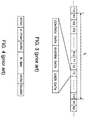
- FIG. 3 shows, in a schematic and illustrative manner, a digital data stream in accordance with the Digital Enhanced Cordless Telecommunication (DECT) standard.
- DECT Digital Enhanced Cordless Telecommunication
- Figure 4 shows, in detail, the structure of a time slot of the data stream of figure 3.
- Figure 5 shows, in a schematic and illustrative manner, an example of transmission cells encountered in practice.
- Figure 6 shows a simplified block diagram of a central interface unit operating in accordance with the present invention.
- FIG. 7 shows a simplified block diagram of a radio access unit operating in accordance with the present invention.
- the invention will now be explained by its application in a cordless radio telephone system, such as a radio telephone system operating in accordance with the Digital Enhanced Cordless Telecommunications (DECT) standard, the Personal Handyphone System (PHS) standard or any cordless radio communication protocol, such as designated CT0, CT1, CT3 etc. Further, the invention is also applicable in a mobile radio communication system, such as operating following the Global System for Mobile communications (GSM) standard or any other mobile communications standard.
- GSM Global System for Mobile communications
- FIG. 1 illustrates a cordless radio telecommunication system, operating in accordance with the present invention, generally designated with reference numeral 1.
- the system 1 comprises three essential elements: a Central Interface Unit (CIU) or radio exchange 2, a plurality of compact Radio Access Units (RAU's) or base stations 3, which are spread over the area to be covered and connect directly to the CIU 2, and remote cordless or wireless radio terminal devices in the form of portable telephones or handsets 4 which connect over an air interface or radio link 9 to the radio access units 3.
- CIU Central Interface Unit
- RAU's Compact Radio Access Units
- base stations which are spread over the area to be covered and connect directly to the CIU 2
- remote cordless or wireless radio terminal devices in the form of portable telephones or handsets 4 which connect over an air interface or radio link 9 to the radio access units 3.
- Each radio access unit 3 provides service to a given area, called a cell 10.
- the cells 10 of the different radio access units 3 are arranged in an overlapping manner, i.e. a so-called multi-cell approach.
- the radius of indoor cells amounts typically from 10 m-100 m, whereas the radius of outdoor cells typically ranges from 200 m up to 5000 m.
- the CIU 2 is connected to a wired exchange 5 to which a plurality of wired telephones 6 can connect.
- this exchange 5 is generally a PABX (Private Automatic Branch eXchange) whereas in outdoor applications, such as Radio in the Local Loop (RLL) or Cordless Terminal Mobility (CTM), the exchange 5 is generally a Local Exchange (LE) which, like the PABX, is connected to a Public Switched Telephone Network (PSTN) or Integrated Services Digital Network (ISDN) 7, i.e. the public telephone and/or data network.
- PSTN Public Switched Telephone Network
- ISDN Integrated Services Digital Network
- the radio access units 3 may also connect over an air link 9 with so-called (Wireless) Fixed Access Units ((W)FAU) 8 which connect to a fixed telephone terminal or socket for the connection of a wired telephone 6.
- (W)FAU) 8 In CTM or RLL providing local mobility in the home, for example, the (W)FAU 8 is arranged to establish an air link with a handset 4 in the home (not shown).
- the transmission links 11, 12, 13 between the radio access units RAU1, RAU2, RAU3 and the central interface unit 2 will have different path lengths.
- These transmission links can take any suitable form, such as wired cable, coaxial cable, optical fiber cable or a radio link in a true wireless radio telecommunication system. It will be appreciated that information transferred between a radio access unit 3 and the central interface unit 2 will experience a propagation delay, dependent on the length and type of the transmission paths, and delays in transceiver equipment.
- Figure 2 illustrates the effect of the propagation delay on the transmission paths 11, 12, 13.
- the horizontal axis represents a time axis.
- T 1 , T 2 and T 3 represent the total propagation delay of the signal 14 while travelling to the relevant radio access unit. Note that the delay time values are chosen for illustrative purposes only.
- the radio access units 3 transmit at the air interface 9 the signal 14 as it is received, it will be clear that the several signals 14 are not synchronously transmitted at the air interface 9. That is, the signal of RAU1 appears first at the air interface, followed by RAU2 and RAU3.
- a radio terminal device 4 travelling from the coverage area or cell of RAU1 to the cell of RAU2 will have to synchronise itself to the RAU2 before communication can be handed over from RAU1 to RAU2. This will cause a drop in the communication, unless the radio terminal device is equipped with dual transceiver means.
- a frame type mode of operation of the radio telecommunication system 1 such as operation in accordance with a Time Division Multiple Access (TDMA) mode wherein a frame is subdivided in several time slots
- TDMA Time Division Multiple Access
- the radio access units 3 at the air interface 9 have to operate in a synchronous manner which, besides stable time base generator means in the several radio access units 3, requires also compensation of the time delays experienced at the transmission links 11, 12, 13. Compensation of the transmission time delays T 1 , T 2 , T 3 can be provided for either at the central interface unit 2 or the radio access units 3. By providing additional propagation time delay at the several transmission paths 11, 12, 13 such that the total delay of each path at least equals the longest transmission delay of the system, all the radio access units 3 will exchange information on the air interface 9 in a synchronous manner.
- the differences in the transmission time delays T 1 , T 2 and T 3 are established from the relative time difference between the transmission and reception of a radio signal between adjacent radio access units 3. To illustrate this method, reference is first made to figure 1.
- radio signals transmitted from RAU1 are received by RAU2, for example.
- RAU2 radio signals transmitted from RAU1
- RAU2 for example.
- the bold printed solid lines 15, 16, 17 represent the time bases of the respective radio access units RAU1, RAU2, RAU3, respectively.
- the time base generator means of the radio access units are controlled by the central interface unit, such that the time bases of the radio access units also experience the transmission time delays T 1 , T 2 , T 3 at the transmission links 11, 12, 13 respectively.
- a radio signal transmitted by RAU1 is received by RAU2 after an air propagation time delay of T 12 .
- the indices 1,2 indicate that the radio signal is transmitted from RAU1 and received by RAU2.
- a radio signal transmitted from RAU2 will be received by RAU1 after a delay T 21 and also by RAU3 after a time T 23 (see figure 1).
- a radio signal 18 transmitted at time t 1 from RAU1 relative to its time base 15 will be received by RAU2 relative to its time base 16 after time t 2 .
- a radio signal 19 transmitted by RAU2 at time t 3 relative to its time base 16 will be received by RAU1 relative to its time base 15 after time t 4 .
- the times t 1 , t 2 , t 3 and t 4 can be separately reported to the central interface unit 2.
- all radio access units 3 will transmit and receive at their air interface 9 in a global synchronous manner. That is, global to the system 1.
- the process has to be extended, such to obtain relative delays of adjacent radio access units corresponding to different systems.
- the time of transmission of a radio signal 18, 19 from a radio access unit 3 can be transmitted with the radio signal, such that a receiving access unit 3 can establish the time difference between transmission and receipt of a particular radio signal, i.e. t 1 - t 2 and t 3 - t 4 .
- the starting point of a frame can be used as internal time base reference, for example. Note that for the purpose of the present invention the system initially does not have to operate synchronous at the air interface 9.
- the radio access units 3 can be arranged such that the radio signal is always transmitted at a fixed position in a frame. Note that more than one radio signal may be transmitted in the same frame.
- the predetermined position can be choosen as the first slot in the frame or any other position which can be determined.
- figure 3 shows the frame structure used in DECT.
- DECT operates in accordance with a TDMA/TDD (Time Division Duplex) protocol, wherein the first half of a frame is used for transmission and the other half of the frame is used for reception purposes, or vice versa.
- a DECT frame comprises twenty-four time slots as shown in figure 3.
- the first half of the frame i.e. the first twelve time slots designated R1, R2, . . .R12
- data transmitted from the radio access units 3 are received by the handsets 4 or (W)FAU 8
- the remote terminal units 4 or 8 transmit data to the radio access units 3.
- a radio communication link between a radio access unit 3 and a remote terminal unit 4 or 8 is assigned a slot in the first half of the frame and a slot bearing the same number in the second half of the frame.
- Each time-slot typically contains control data, system data and information or user data. In DECT, multiple time-slots may be assigned to a particular radio link 9.
- the control data field contains a so-called synchronisation (SYNC) word, which has to be correctly identified at a radio access unit 3 or a remote terminal unit 4, 8 in order to process the received data.
- SYNC data will typically needs 16 bits, proceeded by a preamble of 16 bits.
- the system data field contains system information on identity and access rights, services availability and, if required, information for handover to another communication channel in case of disturbances or transfer of a call to another radio access unit. Also paging and calls set up procedures are carried over the system data field, which is also called A-field.
- System data will typically need 64 bits with a 16 bit Cyclic Redundancy Checkword designates ACRC.
- the information or user data also called B-field, comprise in case of a telephone call digitised speech examples obtained during the frame cycle time T f of 10 ms.
- the speech samples are coded having a typical bit rate of 32 kb/s. This means that for each speech call 320 bits have to be transmitted and received during each frame.
- the B-field date is scrambled and a 4 bit Cyclic Redundancy Checkword, designated XCRC, is formed from the information data. Including guard space, the total number of bits per time-slot according to the DECT standard amounts to 480. These bits are transmitted at a system clock frequency or system bit rate of 1152 kb/s.
- DECT radio communication networks may comprise several DECT radio communication systems 1, which can be independently operated by one or more operators, for example. Further, several DECT radio communication systems 1 may be operated independently in the same geographical area.
- the radio signal for the purpose of the present invention can be transmitted, for example, in the A-field of a predetermined time-slot, for example time-slot 1 of each frame.
- the relevant time of transmission of a radio signal is known, such that only the time of reception of a radio signal has to be transferred for the calculation of the transmission time delays T 1 , T 2 , T 3 etc.
- a radio access unit which receives a radio signal can identify the source of the information, i.e. the transmitting radio access unit.
- this is no constraint because the identification data is always present in either a system or a control data field of the frame.
- obtaining the identification information from the frame requires reception of data not exceeding a certain bit error rate which puts a limitation on the distance between radio access units, which should be within in the coverage area for data transmission, i.e. speech transmission for example.
- the need for the receipt of identification data or the like can be avoided by, under the control of the central interface unit 2, for example, having the radio access units 3 sequentially transmitting a radio signal for the purpose of establishing transmission time delays.
- a receiving radio access unit does not need to know from which radio access unit it receives the radio signal. This information is known at the central interface unit 2. Accordingly, the receiving radio access unit only needs to report its time of receipt from which - and the predetermined time of transmission of each radio access unit - the central interface unit 2 or any other processing unit can calculate the relative transmission time delays.
- Radio signals, not requiring a particular bit error rate, can be received at a greater distance, such that the radio access units 3 can be installed with a distance to cover optimally the area of interest and such that handovers can be made for a remote radio communication unit such as a radio telephone 4 moving across the coverage area from one cell 10 to the other, for example.
- a remote radio communication unit such as a radio telephone 4 moving across the coverage area from one cell 10 to the other, for example.
- Figure 5 shows an actual coverage pattern of a radio telecommunication system, from which it is clear that the method according to the invention will not impose additional restrictions on the positioning of the radio access units 3.
- neighbouring radio access units can not receive each other, there is most probably no need for mutual compensation of transmission time delays, because no handovers can be made within the coverage area of the system. This can be, for example, also the case if the system contains clusters of remote radio access units, such that between clusters no handover is possible.
- a Received Signal Strength Indication (RSSI) value can be obtained at the receiving radio access units, and such that only signals having a strength above a certain level will be used for the purpose of the present invention. This not only speeds up the process as a whole, but also enhances its reliability.
- RSSI Received Signal Strength Indication
- the method according to the invention can be used not only after the installation of a new system, but also during it operation, after maintenance or the repair of failures, or the addition of new radio access units.
- An additional advantage of the method according to the invention is in that if a radio access unit does not respond, this can be an identification of an alleged malfunctioning and can be reported to an operator.
- Figure 6 shows a functional block diagram of an embodiment of a central interface unit 2 for use with the present invention.
- the CIU 2 comprises a housing 20 containing a Central Processing Unit (CPU) 21, Speech Processing Units (SPU) 22, Cell Link Units (CLU) 23 and Line Termination Units (LTU) 24 and/or Digital Trunk Units (DTU) 25.
- CPU Central Processing Unit
- SPU Speech Processing Units
- CLU Cell Link Units
- LTU Line Termination Units
- DTU Digital Trunk Units
- the several units are connected to a digital system bus 29, and are powered by a Power Supply Unit (PSU) 26.
- PSU Power Supply Unit
- the LTU's 24 provide an analogue interface between the PABX 5 and the CIU 2.
- Each LTU 24 comprises a number of line termination circuits, each of which interfaces to the PABX 5 through a 2-wire analogue subscriber line 27. Every analogue line 27 is dedicated to a specific handset 4 or (W)FAU 8 (Fig. 1), i.e. a specific telephone number.
- the main tasks of an LTU are: to establish a physical connection between the PABX and the CIU, on/of hook detection, ring signal detection, and analogue to digital speech processing (PCM) and vice versa.
- PCM digital speech processing
- the DTU 25 provides a digital interface between the PABX 5 and the CIU 2.
- Each DTU 25 contains a number of digital trunk circuits.
- Each digital trunk circuit supports a Channel Associated Signalling (CAS) interface.
- CAS Channel Associated Signalling
- each CAS interface provides thirty fixed 64 kb/s digital communication channels, to which thirty subscribers are assigned; i.e. a 2 Mb/s dataline 28.
- Dependent on the type of the PABX 5 a number of the functions of an LTU may also have to be performed by a DTU.
- up to 600 subscribers can be connected to one CIU 2.
- an interface 30 is provided for control purposes.
- the CIU 2 comprises means 31 for the control of the radio access units 3, such to transmit radio signals and to receive transmitted radio signals, and to store and process received time information of the radio access units 3 for the calculation of the transmission time delays at the links between the CIU 2 and the radio access units 3.
- the CLU's 23 are arranged to compensate for the transmission time delays T 1 , T 2 , T 3 etc.
- FIG. 7 shows a block diagram of a radio access unit 40 which operates in accordance with the present invention.
- the radio access unit 40 has a wired connection 41 to a central interface unit 2, shown in figure 1.
- Central control and application logic 42 detects incoming calls and controls outgoing calls and selects suitable combinations of carrier and time-slots. The different connections and time-slots are merged via a multiplexer 43.
- the radio access unit 40 has a frame and a slot synchronisation unit 44 which controls slot reception and transmission timing.
- the central control logic 42 also controls a Transmit/Receive (T/R) switch 45 and an antenna diversity switch 46, if antenna diversity is implemented. With antenna diversity, two antennas 55 are provided at a radio access unit and, if a radio connection provides no good communication, the control logic first tries the other antenna before changing the radio communication channel.
- T/R Transmit/Receive
- the receiver means of the radio access unit 40 consists of a receiver/demodulator 47 and a transmitter/modulator 48. Synchronisation and control information is stripped from received data by unit 49, whereas such information is added to the data to be transmitted by unit 50, connected as shown.
- the frame and slot synchronisation unit 44 is controlled such to support handover in case of moving remote radio communication terminals 4 (fig. 1).
- the frame and slot synchronisation unit 44 comprises time base generator means 51 and means 52 for measuring the time of reception of a received radio signal, e.g. counter means clocked by the time base generator means 51.
- the measuring means 52 are operative such that transmission delays in the radio access unit itself are compensated for.
- the time of reception of radio signals are measured with respect to the time base generator means 51.
- the signal strength of received radio signals RSSI is measured by means 53.
- the measured and/or received timing information and RSSI values are, under the control of the central control and application logic 42 processed and transferred to the central interface unit 2 or another processing unit for the purpose of the present invention.
- the radio access unit 40 may be provided with delay compensation means 54, in order to compensate for the transmission time delays at the transmission links (11, 12, 13) between the radio access units 3 and the central interface unit 2.
- the means 54 may be set from the CIU 2 and the relevant transmission link 41 or even through the air interface 9 and the receiver/demodulator 47, the unit 49 and the central control and application logic 42 from a remote radio unit, which may be a remote radio unit specially adapted for the purpose of setting time delays in a radio access unit 40, for example.
Landscapes
- Engineering & Computer Science (AREA)
- Computer Networks & Wireless Communication (AREA)
- Signal Processing (AREA)
- Mobile Radio Communication Systems (AREA)
- Monitoring And Testing Of Transmission In General (AREA)
- Measurement Of Unknown Time Intervals (AREA)
- Transceivers (AREA)
Priority Applications (9)
| Application Number | Priority Date | Filing Date | Title |
|---|---|---|---|
| EP96203732A EP0851608A1 (fr) | 1996-12-31 | 1996-12-31 | Mesure du retard de temps de transmission dans les voies de transmission d'un système de télécommunication radio |
| EP97954431A EP0950290B1 (fr) | 1996-12-31 | 1997-12-12 | Mesure de la temporisation de la transmission au niveau des trajectoires de transmission dans un systeme de radiotelecommunication |
| PCT/EP1997/007150 WO1998029964A1 (fr) | 1996-12-31 | 1997-12-12 | Mesure de la temporisation de la transmission au niveau des trajectoires de transmission dans un systeme de radiotelecommunication |
| DK97954431T DK0950290T3 (da) | 1996-12-31 | 1997-12-12 | Måling af transmissionstidsforsinkelse på transmissionsveje i et radiotelekommunikationssystem |
| CN97181091A CN1096769C (zh) | 1996-12-31 | 1997-12-12 | 无线电通信系统中传输路径上传输时延的测量 |
| AU58584/98A AU729504B2 (en) | 1996-12-31 | 1997-12-12 | Transmission time delay measurement at transmission paths in a radio telecommunication system |
| US09/331,871 US6308078B1 (en) | 1996-12-31 | 1997-12-12 | Transmission time delay measurement at transmission paths in a radio telecommunication system |
| DE69706068T DE69706068T2 (de) | 1996-12-31 | 1997-12-12 | Übertragungszeitverzögerungsmessung bei übertragungswegen in einem funk-telekommunikationssystem |
| AT97954431T ATE204107T1 (de) | 1996-12-31 | 1997-12-12 | Übertragungszeitverzögerungsmessung bei übertragungswegen in einem funk- telekommunikationssystem |
Applications Claiming Priority (1)
| Application Number | Priority Date | Filing Date | Title |
|---|---|---|---|
| EP96203732A EP0851608A1 (fr) | 1996-12-31 | 1996-12-31 | Mesure du retard de temps de transmission dans les voies de transmission d'un système de télécommunication radio |
Publications (1)
| Publication Number | Publication Date |
|---|---|
| EP0851608A1 true EP0851608A1 (fr) | 1998-07-01 |
Family
ID=8224776
Family Applications (2)
| Application Number | Title | Priority Date | Filing Date |
|---|---|---|---|
| EP96203732A Withdrawn EP0851608A1 (fr) | 1996-12-31 | 1996-12-31 | Mesure du retard de temps de transmission dans les voies de transmission d'un système de télécommunication radio |
| EP97954431A Expired - Lifetime EP0950290B1 (fr) | 1996-12-31 | 1997-12-12 | Mesure de la temporisation de la transmission au niveau des trajectoires de transmission dans un systeme de radiotelecommunication |
Family Applications After (1)
| Application Number | Title | Priority Date | Filing Date |
|---|---|---|---|
| EP97954431A Expired - Lifetime EP0950290B1 (fr) | 1996-12-31 | 1997-12-12 | Mesure de la temporisation de la transmission au niveau des trajectoires de transmission dans un systeme de radiotelecommunication |
Country Status (8)
| Country | Link |
|---|---|
| US (1) | US6308078B1 (fr) |
| EP (2) | EP0851608A1 (fr) |
| CN (1) | CN1096769C (fr) |
| AT (1) | ATE204107T1 (fr) |
| AU (1) | AU729504B2 (fr) |
| DE (1) | DE69706068T2 (fr) |
| DK (1) | DK0950290T3 (fr) |
| WO (1) | WO1998029964A1 (fr) |
Cited By (3)
| Publication number | Priority date | Publication date | Assignee | Title |
|---|---|---|---|---|
| WO2000064091A3 (fr) * | 1999-04-16 | 2001-01-11 | Siemens Inf & Comm Networks | Procede et systeme servant a synchroniser des stations de base dans des reseaux de telecommunication numeriques |
| WO2005006801A3 (fr) * | 2003-07-10 | 2005-05-06 | Matsushita Electric Industrial Co Ltd | Systeme de radiocommunications et procede de communication |
| CN111399434A (zh) * | 2018-12-27 | 2020-07-10 | 太阳Hst株式会社 | 利用基于超宽带的实时定位的安全事故控制系统 |
Families Citing this family (17)
| Publication number | Priority date | Publication date | Assignee | Title |
|---|---|---|---|---|
| JPH10190562A (ja) * | 1996-12-26 | 1998-07-21 | Toshiba Corp | 移動通信システムの基地局間フレーム同期方式およびこの方式を適用した基地局装置 |
| EP0985300A2 (fr) * | 1998-03-26 | 2000-03-15 | Koninklijke Philips Electronics N.V. | Reseau de communication pour la transmission de cellules mta via une trame du type dect |
| US6975877B1 (en) | 2001-10-17 | 2005-12-13 | Cisco Technology, Inc. | System and method for synchronizing clock dividers in a wireless network |
| DE10255050A1 (de) * | 2002-11-26 | 2004-06-09 | Abb Research Ltd. | Verfahren zum Betrieb eines drahtlosen Kommunikationssystems mit mehreren benachbarten Basisstationen unter Einsatz von Time Division Multiple Access und Frequency Hopping |
| JP4346996B2 (ja) * | 2003-08-29 | 2009-10-21 | 株式会社日立コミュニケーションテクノロジー | 移動通信システム |
| CN100350763C (zh) * | 2004-01-02 | 2007-11-21 | 上海欣泰通信技术有限公司 | 应用于电信网的时间供给与同步系统 |
| CN100358386C (zh) * | 2004-11-01 | 2007-12-26 | 华为技术有限公司 | 一种测量网络无线侧时延的方法 |
| JP4651364B2 (ja) * | 2004-11-17 | 2011-03-16 | 富士通株式会社 | 位相調整方法及び装置 |
| US7808913B2 (en) * | 2005-04-15 | 2010-10-05 | New Jersey Institute Of Technology | Dynamic bandwidth allocation and service differentiation for broadband passive optical networks |
| CN101039154B (zh) * | 2006-03-15 | 2010-08-25 | 联芯科技有限公司 | 一种获取用户终端收发通道传输时间的方法 |
| CN101064950B (zh) * | 2006-04-29 | 2010-04-07 | 联芯科技有限公司 | 一种获取用户终端收发通道传输时间的方法 |
| US7809404B2 (en) * | 2006-11-08 | 2010-10-05 | Intel Corporation | MIMO passive channel emulator |
| US9197691B2 (en) | 2011-10-04 | 2015-11-24 | Google Technology Holdings LLC | System and method for latency measurement at each network element participating as an RTP relay in a telecommunication network |
| CN104244399B (zh) | 2014-09-15 | 2018-04-17 | 歌尔股份有限公司 | 无线设备间时间同步的方法、无线设备和无线通信系统 |
| US10939400B2 (en) * | 2017-12-19 | 2021-03-02 | Qualcomm Incorporated | Time synchronization techniques for wireless communications |
| CN109634897A (zh) * | 2018-12-20 | 2019-04-16 | 宁波三星智能电气有限公司 | 基于分立式非标mbus通信方法 |
| WO2022151218A1 (fr) * | 2021-01-14 | 2022-07-21 | 捷开通讯(深圳)有限公司 | Procédé, appareil et dispositif de compensation de retard de propagation, station de base, système et support |
Citations (9)
| Publication number | Priority date | Publication date | Assignee | Title |
|---|---|---|---|---|
| EP0197556A2 (fr) * | 1985-04-10 | 1986-10-15 | Tecnomen Oy | Méthode de synchronisation pour transmetteurs radio dans un réseau d'appel local, par exemple national |
| US4709401A (en) * | 1982-09-12 | 1987-11-24 | Telefonaktiebolaget Lm Ericsson | Method of setting radio transmitters for synchronous radio transmission |
| US4718109A (en) * | 1986-03-06 | 1988-01-05 | Motorola, Inc. | Automatic synchronization system |
| EP0286614A1 (fr) * | 1987-04-03 | 1988-10-12 | Telefonaktiebolaget L M Ericsson | Procédé et dispositif de synchronisation et transmission d'information dans un système de radiocommunications |
| EP0437835A1 (fr) | 1989-12-27 | 1991-07-24 | Nec Corporation | Système de synchronisation de trames parmi plusieurs stations de base radio, pour un système de communication mobile numérique AMRT |
| US5128925A (en) * | 1989-04-25 | 1992-07-07 | Matra Communication | Process for the pseudo-synchronization of a time multiplexing communication network and uses thereof |
| EP0560079A1 (fr) * | 1992-03-05 | 1993-09-15 | Tecnomen Oy | Procédé de radiosynchronisation de stations de base dans un réseau à onde commune |
| EP0626796A1 (fr) | 1993-05-28 | 1994-11-30 | Siemens Aktiengesellschaft | Procédé pour synchroniser les stations de base dans un système radiotéléphonique multicellulaire |
| WO1994028643A1 (fr) * | 1993-05-27 | 1994-12-08 | Nokia Telecommunications Oy | Station de base pour reseau radio cellulaire amrt |
-
1996
- 1996-12-31 EP EP96203732A patent/EP0851608A1/fr not_active Withdrawn
-
1997
- 1997-12-12 DK DK97954431T patent/DK0950290T3/da active
- 1997-12-12 AT AT97954431T patent/ATE204107T1/de not_active IP Right Cessation
- 1997-12-12 CN CN97181091A patent/CN1096769C/zh not_active Expired - Lifetime
- 1997-12-12 DE DE69706068T patent/DE69706068T2/de not_active Expired - Lifetime
- 1997-12-12 WO PCT/EP1997/007150 patent/WO1998029964A1/fr not_active Ceased
- 1997-12-12 EP EP97954431A patent/EP0950290B1/fr not_active Expired - Lifetime
- 1997-12-12 US US09/331,871 patent/US6308078B1/en not_active Expired - Lifetime
- 1997-12-12 AU AU58584/98A patent/AU729504B2/en not_active Expired
Patent Citations (9)
| Publication number | Priority date | Publication date | Assignee | Title |
|---|---|---|---|---|
| US4709401A (en) * | 1982-09-12 | 1987-11-24 | Telefonaktiebolaget Lm Ericsson | Method of setting radio transmitters for synchronous radio transmission |
| EP0197556A2 (fr) * | 1985-04-10 | 1986-10-15 | Tecnomen Oy | Méthode de synchronisation pour transmetteurs radio dans un réseau d'appel local, par exemple national |
| US4718109A (en) * | 1986-03-06 | 1988-01-05 | Motorola, Inc. | Automatic synchronization system |
| EP0286614A1 (fr) * | 1987-04-03 | 1988-10-12 | Telefonaktiebolaget L M Ericsson | Procédé et dispositif de synchronisation et transmission d'information dans un système de radiocommunications |
| US5128925A (en) * | 1989-04-25 | 1992-07-07 | Matra Communication | Process for the pseudo-synchronization of a time multiplexing communication network and uses thereof |
| EP0437835A1 (fr) | 1989-12-27 | 1991-07-24 | Nec Corporation | Système de synchronisation de trames parmi plusieurs stations de base radio, pour un système de communication mobile numérique AMRT |
| EP0560079A1 (fr) * | 1992-03-05 | 1993-09-15 | Tecnomen Oy | Procédé de radiosynchronisation de stations de base dans un réseau à onde commune |
| WO1994028643A1 (fr) * | 1993-05-27 | 1994-12-08 | Nokia Telecommunications Oy | Station de base pour reseau radio cellulaire amrt |
| EP0626796A1 (fr) | 1993-05-28 | 1994-11-30 | Siemens Aktiengesellschaft | Procédé pour synchroniser les stations de base dans un système radiotéléphonique multicellulaire |
Non-Patent Citations (1)
| Title |
|---|
| YOSHIHIKO AKAIWA, ET AL.: "Autonomous Decentralized Inter-Base-Station Synchronisation for TDMA Microcellular Systems", IEEE, pages 257 - 262 |
Cited By (5)
| Publication number | Priority date | Publication date | Assignee | Title |
|---|---|---|---|---|
| WO2000064091A3 (fr) * | 1999-04-16 | 2001-01-11 | Siemens Inf & Comm Networks | Procede et systeme servant a synchroniser des stations de base dans des reseaux de telecommunication numeriques |
| WO2005006801A3 (fr) * | 2003-07-10 | 2005-05-06 | Matsushita Electric Industrial Co Ltd | Systeme de radiocommunications et procede de communication |
| US8416704B2 (en) | 2003-07-10 | 2013-04-09 | Panasonic Corporation | Radio communication system and communication method |
| CN111399434A (zh) * | 2018-12-27 | 2020-07-10 | 太阳Hst株式会社 | 利用基于超宽带的实时定位的安全事故控制系统 |
| CN111399434B (zh) * | 2018-12-27 | 2023-10-20 | 太阳Hst株式会社 | 利用基于超宽带的实时定位的安全事故控制系统 |
Also Published As
| Publication number | Publication date |
|---|---|
| DE69706068T2 (de) | 2002-04-25 |
| DK0950290T3 (da) | 2001-10-22 |
| EP0950290B1 (fr) | 2001-08-08 |
| US6308078B1 (en) | 2001-10-23 |
| WO1998029964A1 (fr) | 1998-07-09 |
| DE69706068D1 (de) | 2001-09-13 |
| CN1096769C (zh) | 2002-12-18 |
| EP0950290A1 (fr) | 1999-10-20 |
| AU729504B2 (en) | 2001-02-01 |
| ATE204107T1 (de) | 2001-08-15 |
| CN1242119A (zh) | 2000-01-19 |
| AU5858498A (en) | 1998-07-31 |
Similar Documents
| Publication | Publication Date | Title |
|---|---|---|
| EP0950290B1 (fr) | Mesure de la temporisation de la transmission au niveau des trajectoires de transmission dans un systeme de radiotelecommunication | |
| AU711603B2 (en) | Digital mobile communication system capable of establishing mutual synchronization among a plurality of radio base stations | |
| US5537685A (en) | Method of establishing inter-base-station synchronization and mobile radio communication system using the method | |
| AU647062B2 (en) | Frame synchronization system among multiple radio base stations for TDMA digital mobile communications system | |
| US6014376A (en) | Method for over-the-air synchronization adjustment in a communication system | |
| JP4741030B2 (ja) | 送信方法及びセルラー無線システム | |
| US5519710A (en) | Network synchronization for TDMA cellular communication using signals from mobile stations in neighboring cells | |
| CA2216580C (fr) | Procede et systeme permettant de determiner le parametre pscn en partant du parametre mfn dans un systeme de telephone sans fil dect | |
| JPH03224325A (ja) | Tdmaディジタル移動通信システム | |
| US20050007998A1 (en) | Packet switched data network for transferring data packets with a predetermined delay and a radio communication network equipped with such a data network | |
| US5974321A (en) | Method for selecting a signal, and a cellular radio system | |
| US7499706B1 (en) | Network frequency setting | |
| US20020019242A1 (en) | Device and method for cordless transmission of telephone calls via a number of base stations to mobile dect telephones | |
| EP1099316B1 (fr) | Procede et dispositif de selection d'antenne dans un systeme de telecommunication numerique | |
| KR20000008731A (ko) | 무선 사설교환시스템의 기지국간 동기화 장치 및 방법 | |
| EP0613276B1 (fr) | Système de synchronisation de plusieurs émetteurs radio | |
| EP1410530A1 (fr) | Dispositif et procede de synchronisation d'un element de reseau de telecommunications | |
| JPH08154271A (ja) | ディジタルコードレス電話システムにおける基地局間同期装置 |
Legal Events
| Date | Code | Title | Description |
|---|---|---|---|
| PUAI | Public reference made under article 153(3) epc to a published international application that has entered the european phase |
Free format text: ORIGINAL CODE: 0009012 |
|
| AK | Designated contracting states |
Kind code of ref document: A1 Designated state(s): AT BE CH DE DK ES FI FR GB GR IE IT LI LU MC NL PT SE |
|
| AKX | Designation fees paid | ||
| RBV | Designated contracting states (corrected) | ||
| STAA | Information on the status of an ep patent application or granted ep patent |
Free format text: STATUS: THE APPLICATION IS DEEMED TO BE WITHDRAWN |
|
| 18D | Application deemed to be withdrawn |
Effective date: 19990105 |