EP0851644A2 - Radiotéléphone - Google Patents
Radiotéléphone Download PDFInfo
- Publication number
- EP0851644A2 EP0851644A2 EP97310083A EP97310083A EP0851644A2 EP 0851644 A2 EP0851644 A2 EP 0851644A2 EP 97310083 A EP97310083 A EP 97310083A EP 97310083 A EP97310083 A EP 97310083A EP 0851644 A2 EP0851644 A2 EP 0851644A2
- Authority
- EP
- European Patent Office
- Prior art keywords
- shaft
- radiotelephone
- hinge
- limbs
- spring
- Prior art date
- Legal status (The legal status is an assumption and is not a legal conclusion. Google has not performed a legal analysis and makes no representation as to the accuracy of the status listed.)
- Granted
Links
Images

Classifications
-
- H—ELECTRICITY
- H04—ELECTRIC COMMUNICATION TECHNIQUE
- H04M—TELEPHONIC COMMUNICATION
- H04M1/00—Substation equipment, e.g. for use by subscribers
- H04M1/02—Constructional features of telephone sets
- H04M1/0202—Portable telephone sets, e.g. cordless phones, mobile phones or bar type handsets
- H04M1/0206—Portable telephones comprising a plurality of mechanically joined movable body parts, e.g. hinged housings
- H04M1/0208—Portable telephones comprising a plurality of mechanically joined movable body parts, e.g. hinged housings characterized by the relative motions of the body parts
- H04M1/0214—Foldable telephones, i.e. with body parts pivoting to an open position around an axis parallel to the plane they define in closed position
- H04M1/0216—Foldable in one direction, i.e. using a one degree of freedom hinge
Definitions
- the present invention relates to a radiotelephone and, more particularly, to the mechanical structure of a radiotelephone having first and second housing portions connected by a hinge.
- the hinge of this type of radiotelephone enables the housing portions to be folded between a compact closed position and an open position in which it is ready for use.
- the present invention may provide a radiotelephone comprising first and second housing portions connected by a hinge, wherein the hinge shaft is located between a pair of spring limbs elongate parallel to the axis of the shaft and converging to engage partway along their lengths a cam portion of the shaft so as to influence by cam action the operation of the hinge.
- This structure of hinge enables relatively large spring limbs to be used as the limbs are elongate, and interact with the hinge shaft, along its largest dimension - its axis. Because of their size, the spring limbs can operate comfortably within their specification for the projected life of the hinge.
- the spring are constrained from movement at both ends thereof.
- Such constraint produces a high degree of resistance to the operation of the hinge (in comparison with an arrangement in which at least one end of the limbs is free to diverge and converge under the influence of the cam portion) which affords a favourable, positive sensation to the user.
- the limbs conveniently may form part of a single spring member, preferably a U-shaped spring.
- the hinge shaft projects from the open end of the spring partially along the length of the limbs. In this way, a region between the limbs and beyond the projecting end of the shaft is created. Within this region, a transducer or other component, preferably a microphone, can be advantageously located.
- the spring may be affixed to the rest of the radiotelephone via its closed end.
- the present invention may provide a radiotelephone comprising first and second housing portions connected by a hinge, the hinge comprising a mounting structure on the first housing portion, a shaft projecting into the mounting structure and rotatably connecting the mounting structure and the second housing portion and thereby defining an axis of rotation of the hinge, the shaft including a cam portion, spring means located in the mounting structure and including a pair of limbs elongate parallel to the axis of the shaft, the limbs converging to engage partway along their lengths the cam portion so as to apply a rotational bias to it, whereby the first and second housing portions can adopt an open bias position and a closed position, and a transducer located between the limbs in a region beyond the projecting end of the shaft.
- This structure of hinge creates a region between the limbs and beyond the projecting end of the shaft in which a transducer can be located.
- the transducer can be a microphone in which case the microphone can be used with the first and second housing portions being either in the open bias position or the closed position.
- the present invention may provide a radiotelephone comprising first and second housing portions connected by a hinge, the hinge comprising first connection means on the first housing portion, second connection means on the second housing portion, the connection means connecting with one another at mutually spaced connection zones such that the first and second housing portions can rotate about an axis of the hinge, the connection means including a shaft projecting from a said connection zone to a spring-contact zone which is intermediate of and remote from the connection zones, and a spring positioned to engage the shaft in the spring-contact zone and apply a rotational bias to it so as to influence the operation of the hinge.
- Figures 1 and 2 show a portable, cellular radiotelephone 20 comprising a main body 24 which is pivotally coupled to a cover 22 by a hinge 40 having an axis of rotation indicated by the line H-H'. (Only a mounting structure 42 of the hinge is visible in Figure 2).
- the main body 24 includes a front case or A-cover 26 and a rear case or B-cover 28.
- a loudspeaker 30 is provided at an upper end portion of the main body 24.
- a display 32 and a keypad 34 are provided at a middle portion of the main body 24.
- a microphone (not visible in Figure 2) is provided at a lower end portion of the main body 24 within the hinge mounting structure 42.
- An aperture 36 is provided in the mounting structure 42 to provide an acoustic path to the microphone.
- the microphone and the loudspeaker 30 are positioned at opposite ends of the main body 24 to maximise the distance between them such that this distance, insofar as is possible given the dimensions of the main body 24, approximates the distance between the ear and mouth of a user.
- Reference numeral 38 refers to a slidable antenna provided at side of the main body 24.
- the radiotelephone 20 is shown in an open position in which the radiotelephone 20 is ready for use and the cover 22 is able to function as a voice reflection and collection member for the microphone.
- the cover 22 can be pivoted by means of the hinge 40 into a compact closed position, as indicated by arrow A, such that it lies on the main body 24 and overlies at least some of the keypad 34.
- the mounting structure 42 protrudes from the front face of the front case 26 and defines an elongate cavity 43 having a longitudinal axis along the axis of rotation H-H' of the hinge 40.
- the cavity 43 is terminated lengthwise by end walls 44a, 44b and widthwise by side walls 46a, 46b.
- a spigot 48 projects from the outside of end wall 44b along the axis H-H'.
- An aperture 50 is provided in the end wall 44a, again, on the axis H-H'.
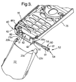
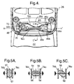
- the aperture 50 receives in a push-fit manner a shaft 52 (best seen itself in Figure 3) as shown in Figure 4.
- the shaft 52 is rotatable in the aperture 50 and its axis lies on the axis H-H'.
- the shaft 52 extends only partially along the length of the cavity and is supported at its projecting end by a cradle 51.
- the shaft 52 includes a cam section 54, a locking section 60, including radially compressible wings 61 enabling the shaft to pushfit in the aperture 50, and a connection section 64.
- the cover 22 is provided with a pair of projecting arms 22a, 22b each having a respective recess 23a, 23b - recess 23a not being visible.
- the recess 23b is shaped to mate with the spigot 48 to allow relative rotation between the recess 23b and the spigot 48
- the recess 23a is shaped to mate with the connection section 64 of the shaft 52 to prevent relative rotation between the recess 23a and the connection section 64 of the shaft 52.
- the cover 22 can thus be removably fastened to the main body 24 by the connection of the arms 22a, 22b with the connection section 64 and the spigot 48, thereby allowing the relative rotation of the main body 24 and the cover 22 about the axis H-H'.
- a generally U-shaped leaf spring 70 is also provided within the mounting structure 42.
- the leaf spring 70 includes a short body segment 72.
- a long limb segment 74a, 74b upstands form each end of the body segment 72 such that the limb segments 74a, 74b lie in opposing relation to each other.
- the leaf spring 70 is secured to the end wall 44b via its body segment 72 using a screw.
- the body segment 72 extends widthwise across the cavity 43.
- the opposing limb segments 74a, 74b extend along the whole length of the cavity 43 and abut the other end wall 44a on opposite sides of the aperture 50 and hence also the shaft 52.
- a pair of formations 45a formed on the end wall 44a define a channel into which the limb segment 74a is snugly received.
- the formations 45a serve to constrain the end of the limb segment 74a.
- a formation 45b formed on the end wall 44a together with the side wall 46b define another channel into which the limb segment 74b is snugly received.
- the formation 45b and the side wall 46b thus together serve to constrain the end of the limb segment 74b.
- the limb segments 74a, 74b may be thought of as being constrained at their other end as a result of upstanding from, and forming part of the same member as, the body segment 72.
- the limb segments 74a, 74b coverage in a central region of the cavity 43 partway along their length. Within this central region, the limb segments 74a, 74b coverage sufficiently to pinch the cam section 54.
- Figures 5(a-c) illustrate the interaction of the leaf spring 70 and the cam section 54 of the shaft 52 as the cover 22 is folded from its Figure 2 open position to the closed position.
- the cam section 54 is octagonal in cross-section and comprises a pair of parallel major faces 56, a pair of parallel minor faces 57, the minor faces 57 being in planes perpendicular to the planes of the major faces 56.
- Each minor face 57 is connected to the major faces by a pair of shoulder faces 58.
- the shaft 52 is in the angular orientation associated with the cover 22 being in its Figure 3 position.
- the limb segments 74a, 74b engage the major faces 56 of the cam section 54 and apply no net torque to the shaft 52.
- the limb segments 74a, 74b serves to hold the shaft 52 stably in this orientation because if the shaft 52 is rotated in either direction, as a result of movement of the cover 22 the limb segments 74a, 74b apply a opposing torque or bias to the shoulder face 58 of shaft 52 which acts to restore the shaft 52 to its Figure 5(a) orientation.
- the shaft 52 is in the angular orientation associated with the cover 22 being partway between its open bias position of Figure 2 and its closed position. In this orientation, the shaft 52 has been rotated in a clockwise direction from Figure 5(a) causing the further separation of the limb segments 74a, 74b until the limb segments 74a, 74b engage the minor faces 57 of the shaft 52 and apply no net torque to the shaft 52.
- the limb segments 74a, 74b serve to hold the shaft 52 in this orientation but if the shaft 52 is rotated in either direction as a result of the movement of the cover 22 the limb segments 74a, 74b apply a torque to the shoulder faces 58 of the shaft 52 which acts to drive the shaft 52 into either its Figure 5(a) or 5(c) orientation. It will be appreciated that in use the cover 22 will usually not be brought to rest such that the shaft 52 can rest in equilibrium in the Figure 5(b) orientation but passes through this orientation as the cover 22 is moved from its open bias position of Figure 2 to its closed position.
- the shaft 52 is in the angular orientation associated with the cover 22 being in its closed position in which it overlies the main body 24.
- the limb segments 74a, 74b engage the a pair of shoulder faces 58 of the shaft 52 such that a net clockwise torque is applied to the shaft 52.
- This net torque is transmitted by the shaft 52 to the cover 22 and causes the cover 22 to be urged towards the main body 24 in its closed position.
- the cover 22 need not be biased by the spring 70 into its closed position, but can be maintained in this position by a fastener or clip mechanism.
- a holder 80 for receiving in a push-fit manner a microphone is formed in the mounting structure 42 between the projecting end of the shaft 52 and the end wall 44b of the cavity 43.
- the shaft 52 is held rotationally fast with the cover 22, and the spring 70 is held rotationally fast with the mounting structure 42 and hence the main body 24 for all possible relative angular positions of the main body 24 and the cover 22.
Landscapes
- Engineering & Computer Science (AREA)
- Signal Processing (AREA)
- Telephone Set Structure (AREA)
- Pivots And Pivotal Connections (AREA)
Applications Claiming Priority (2)
| Application Number | Priority Date | Filing Date | Title |
|---|---|---|---|
| GB9626738A GB2322906B (en) | 1996-12-23 | 1996-12-23 | Spring biased hinge for a foldable radiotelephone |
| GB9626738 | 1996-12-23 |
Publications (3)
| Publication Number | Publication Date |
|---|---|
| EP0851644A2 true EP0851644A2 (fr) | 1998-07-01 |
| EP0851644A3 EP0851644A3 (fr) | 1999-03-31 |
| EP0851644B1 EP0851644B1 (fr) | 2005-08-10 |
Family
ID=10804932
Family Applications (1)
| Application Number | Title | Priority Date | Filing Date |
|---|---|---|---|
| EP97310083A Expired - Lifetime EP0851644B1 (fr) | 1996-12-23 | 1997-12-12 | Radiotéléphone |
Country Status (4)
| Country | Link |
|---|---|
| US (1) | US5983083A (fr) |
| EP (1) | EP0851644B1 (fr) |
| DE (1) | DE69733934T2 (fr) |
| GB (1) | GB2322906B (fr) |
Cited By (6)
| Publication number | Priority date | Publication date | Assignee | Title |
|---|---|---|---|---|
| EP1074685A3 (fr) * | 1999-08-06 | 2001-11-14 | Sugatsune Kogyo Co., Ltd. | Ensemble de charnière |
| EP0935376A3 (fr) * | 1998-02-09 | 2002-04-03 | Sugatsune Industrial Co. Limited | Dispositif de charnière pour un appareil électronique portable |
| EP0961459A3 (fr) * | 1998-05-29 | 2003-07-30 | Nokia Corporation | Mécanisme de charnière pour un téléphone portatif |
| EP1184532A4 (fr) * | 2000-04-04 | 2004-05-26 | Sugatsune Kogyo | Charniere |
| DE102004059236A1 (de) * | 2004-12-08 | 2006-06-14 | Lumberg Connect Gmbh & Co. Kg | Gerät mit relativ zueinander bewegbaren Geräteteilen wie Mobiltelefon mit einer Unterschale und einer Oberschale |
| US7184805B2 (en) * | 2004-04-02 | 2007-02-27 | Samsung Electronics Co., Ltd. | Hinge device of swing-type portable terminal |
Families Citing this family (12)
| Publication number | Priority date | Publication date | Assignee | Title |
|---|---|---|---|---|
| GB2352769B (en) * | 1999-08-06 | 2001-06-20 | Sugatsune Kogyo | Hinge assembly |
| JP2001203791A (ja) * | 2000-01-18 | 2001-07-27 | Strawberry Corporation:Kk | 携帯式電話に付設されるフリップの開閉構造 |
| KR200211457Y1 (ko) * | 2000-08-08 | 2001-01-15 | 엘지정보통신주식회사 | 플립형 휴대전화기 |
| US6525929B2 (en) * | 2001-01-25 | 2003-02-25 | Dell Products L.P. | Computer chassis door with position damping detent hinge |
| TW487258U (en) * | 2001-02-15 | 2002-05-11 | Quanta Comp Inc | Pivot structure of a mobile phone detachable from a base thereof |
| US6530123B1 (en) | 2001-04-17 | 2003-03-11 | Reell Precision Manufacturing Corporation | Clip friction hinge with housing |
| US20020198016A1 (en) * | 2001-06-22 | 2002-12-26 | Gupte Sheel A. | Simple hinge wireless mobile device flip enclosure |
| US7194289B1 (en) * | 2003-06-24 | 2007-03-20 | Flores Jr Bart | Cell phone with mirror |
| JP4187607B2 (ja) * | 2003-08-14 | 2008-11-26 | 富士通株式会社 | 移動式無線通信装置 |
| US20050091431A1 (en) * | 2003-10-23 | 2005-04-28 | Robert Olodort | Portable communication devices |
| KR100582970B1 (ko) * | 2004-07-29 | 2006-05-25 | 삼성전자주식회사 | 도어개폐장치 및 그것을 갖는 전자기기 |
| US20070297027A1 (en) * | 2006-06-14 | 2007-12-27 | Nokia Corporation | Modular spring system |
Family Cites Families (9)
| Publication number | Priority date | Publication date | Assignee | Title |
|---|---|---|---|---|
| AU633405B2 (en) * | 1990-02-27 | 1993-01-28 | Fujitsu Limited | Portable telephone having a cover |
| JPH0491541A (ja) * | 1990-08-07 | 1992-03-25 | Fujitsu Ltd | 電話機用ハンドセット |
| CA2078233A1 (fr) * | 1991-03-28 | 1992-09-29 | Thomas E. Paulick | Charniere de radiotelephone pliant |
| US5185790A (en) * | 1991-03-28 | 1993-02-09 | Motorola, Inc. | Multiposition detenting hinge apparatus |
| BR9205257A (pt) * | 1991-05-06 | 1993-07-27 | Motorola Inc | Aparelho de articulacao |
| US5715575A (en) * | 1995-03-13 | 1998-02-10 | Kato Spring Works Co., Ltd. | Hinge device |
| US5649309A (en) * | 1995-05-18 | 1997-07-15 | Motorola, Inc. | Wireless communication device having an axially aligned cover release mechanism |
| US5661797A (en) * | 1995-11-01 | 1997-08-26 | Nokia Mobile Phones Ltd. | Hinge mechanism for cellular transceiver housing |
| JPH09153931A (ja) * | 1995-11-30 | 1997-06-10 | Mitsubishi Electric Corp | 開閉機構 |
-
1996
- 1996-12-23 GB GB9626738A patent/GB2322906B/en not_active Expired - Fee Related
-
1997
- 1997-12-12 EP EP97310083A patent/EP0851644B1/fr not_active Expired - Lifetime
- 1997-12-12 DE DE69733934T patent/DE69733934T2/de not_active Expired - Lifetime
- 1997-12-18 US US08/993,325 patent/US5983083A/en not_active Expired - Fee Related
Cited By (8)
| Publication number | Priority date | Publication date | Assignee | Title |
|---|---|---|---|---|
| EP0935376A3 (fr) * | 1998-02-09 | 2002-04-03 | Sugatsune Industrial Co. Limited | Dispositif de charnière pour un appareil électronique portable |
| EP0961459A3 (fr) * | 1998-05-29 | 2003-07-30 | Nokia Corporation | Mécanisme de charnière pour un téléphone portatif |
| EP1074685A3 (fr) * | 1999-08-06 | 2001-11-14 | Sugatsune Kogyo Co., Ltd. | Ensemble de charnière |
| KR100377060B1 (ko) * | 1999-08-06 | 2003-03-26 | 스가츠네 고교 가부시키 가이샤 | 힌지 |
| US6587676B1 (en) | 1999-08-06 | 2003-07-01 | Sugatsune Kogyo Co., Ltd. | Hinge assembly |
| EP1184532A4 (fr) * | 2000-04-04 | 2004-05-26 | Sugatsune Kogyo | Charniere |
| US7184805B2 (en) * | 2004-04-02 | 2007-02-27 | Samsung Electronics Co., Ltd. | Hinge device of swing-type portable terminal |
| DE102004059236A1 (de) * | 2004-12-08 | 2006-06-14 | Lumberg Connect Gmbh & Co. Kg | Gerät mit relativ zueinander bewegbaren Geräteteilen wie Mobiltelefon mit einer Unterschale und einer Oberschale |
Also Published As
| Publication number | Publication date |
|---|---|
| GB9626738D0 (en) | 1997-02-12 |
| EP0851644A3 (fr) | 1999-03-31 |
| US5983083A (en) | 1999-11-09 |
| EP0851644B1 (fr) | 2005-08-10 |
| GB2322906B (en) | 2001-04-04 |
| GB2322906A (en) | 1998-09-09 |
| DE69733934D1 (de) | 2005-09-15 |
| DE69733934T2 (de) | 2006-03-09 |
Similar Documents
| Publication | Publication Date | Title |
|---|---|---|
| EP0851644B1 (fr) | Radiotéléphone | |
| JPH04273744A (ja) | 携帯用電話機 | |
| US5369788A (en) | Miniature portable radio communication apparatus | |
| KR100776775B1 (ko) | 동기용 힌지를 갖는 이동단말 | |
| KR101232951B1 (ko) | 시청이 편리한 휴대 단말기 및 그의 슬라이딩 거치 장치 | |
| US5235560A (en) | Wristwatch radiotelephone | |
| US6125509A (en) | Rotation dependent frictional hinge mechanism | |
| US6859978B2 (en) | Flip phone having a hinge mechanism with an auto-lock function | |
| EP0777370A1 (fr) | Téléphone portable muni d'un volet rotatif | |
| US20080081591A1 (en) | Semi-automatic swing device for swing-type portable terminal | |
| US7190797B1 (en) | Headset with foldable noise canceling and omnidirectional dual-mode boom | |
| US7450979B2 (en) | Sliding module for portable terminal | |
| JPH07202748A (ja) | 携帯無線機 | |
| US8996079B2 (en) | Portable terminal with multiple-hinges | |
| CN100433567C (zh) | 具有三联轴铰链折盖的便携式通信设备及其旋转锁扣装置 | |
| JP2910721B2 (ja) | 折り畳み式携帯電話機 | |
| JPH07321524A (ja) | 携帯無線機 | |
| JPH0832088B2 (ja) | 折畳み式携帯電話機 | |
| EP1755318A1 (fr) | Charnière pour dispositif portatif | |
| CN100474095C (zh) | 用于便携无线终端的照相机镜头部件 | |
| US20070041816A1 (en) | Swing-type mobile communication terminal | |
| JP2516353Y2 (ja) | コードレス通信機のアンテナ構造 | |
| KR100739179B1 (ko) | 휴대 단말기 | |
| JP2852267B2 (ja) | 折畳式携帯電話機 | |
| KR100724969B1 (ko) | 휴대용 단말기의 로터리형 힌지 장치 |
Legal Events
| Date | Code | Title | Description |
|---|---|---|---|
| PUAI | Public reference made under article 153(3) epc to a published international application that has entered the european phase |
Free format text: ORIGINAL CODE: 0009012 |
|
| AK | Designated contracting states |
Kind code of ref document: A2 Designated state(s): DE FR GB SE |
|
| AX | Request for extension of the european patent |
Free format text: AL;LT;LV;MK;RO;SI |
|
| PUAL | Search report despatched |
Free format text: ORIGINAL CODE: 0009013 |
|
| AK | Designated contracting states |
Kind code of ref document: A3 Designated state(s): AT BE CH DE DK ES FI FR GB GR IE IT LI LU MC NL PT SE |
|
| AX | Request for extension of the european patent |
Free format text: AL;LT;LV;MK;RO;SI |
|
| 17P | Request for examination filed |
Effective date: 19990930 |
|
| AKX | Designation fees paid |
Free format text: DE FR GB SE |
|
| RAP1 | Party data changed (applicant data changed or rights of an application transferred) |
Owner name: NOKIA CORPORATION |
|
| 17Q | First examination report despatched |
Effective date: 20031117 |
|
| GRAP | Despatch of communication of intention to grant a patent |
Free format text: ORIGINAL CODE: EPIDOSNIGR1 |
|
| GRAA | (expected) grant |
Free format text: ORIGINAL CODE: 0009210 |
|
| GRAS | Grant fee paid |
Free format text: ORIGINAL CODE: EPIDOSNIGR3 |
|
| AK | Designated contracting states |
Kind code of ref document: B1 Designated state(s): DE FR GB SE |
|
| REG | Reference to a national code |
Ref country code: GB Ref legal event code: FG4D |
|
| REF | Corresponds to: |
Ref document number: 69733934 Country of ref document: DE Date of ref document: 20050915 Kind code of ref document: P |
|
| REG | Reference to a national code |
Ref country code: SE Ref legal event code: TRGR |
|
| PGFP | Annual fee paid to national office [announced via postgrant information from national office to epo] |
Ref country code: SE Payment date: 20051206 Year of fee payment: 9 |
|
| ET | Fr: translation filed | ||
| PLBE | No opposition filed within time limit |
Free format text: ORIGINAL CODE: 0009261 |
|
| STAA | Information on the status of an ep patent application or granted ep patent |
Free format text: STATUS: NO OPPOSITION FILED WITHIN TIME LIMIT |
|
| 26N | No opposition filed |
Effective date: 20060511 |
|
| PG25 | Lapsed in a contracting state [announced via postgrant information from national office to epo] |
Ref country code: SE Free format text: LAPSE BECAUSE OF NON-PAYMENT OF DUE FEES Effective date: 20061213 |
|
| EUG | Se: european patent has lapsed | ||
| PGFP | Annual fee paid to national office [announced via postgrant information from national office to epo] |
Ref country code: FR Payment date: 20101224 Year of fee payment: 14 |
|
| PGFP | Annual fee paid to national office [announced via postgrant information from national office to epo] |
Ref country code: GB Payment date: 20101208 Year of fee payment: 14 |
|
| PGFP | Annual fee paid to national office [announced via postgrant information from national office to epo] |
Ref country code: DE Payment date: 20101208 Year of fee payment: 14 |
|
| GBPC | Gb: european patent ceased through non-payment of renewal fee |
Effective date: 20111212 |
|
| REG | Reference to a national code |
Ref country code: FR Ref legal event code: ST Effective date: 20120831 |
|
| REG | Reference to a national code |
Ref country code: DE Ref legal event code: R119 Ref document number: 69733934 Country of ref document: DE Effective date: 20120703 |
|
| PG25 | Lapsed in a contracting state [announced via postgrant information from national office to epo] |
Ref country code: DE Free format text: LAPSE BECAUSE OF NON-PAYMENT OF DUE FEES Effective date: 20120703 Ref country code: GB Free format text: LAPSE BECAUSE OF NON-PAYMENT OF DUE FEES Effective date: 20111212 |
|
| PG25 | Lapsed in a contracting state [announced via postgrant information from national office to epo] |
Ref country code: FR Free format text: LAPSE BECAUSE OF NON-PAYMENT OF DUE FEES Effective date: 20120102 |