EP0851674A2 - Caméra électronique panoramique - Google Patents
Caméra électronique panoramique Download PDFInfo
- Publication number
- EP0851674A2 EP0851674A2 EP97403104A EP97403104A EP0851674A2 EP 0851674 A2 EP0851674 A2 EP 0851674A2 EP 97403104 A EP97403104 A EP 97403104A EP 97403104 A EP97403104 A EP 97403104A EP 0851674 A2 EP0851674 A2 EP 0851674A2
- Authority
- EP
- European Patent Office
- Prior art keywords
- housing
- wheel
- azimuth
- lens
- analog
- Prior art date
- Legal status (The legal status is an assumption and is not a legal conclusion. Google has not performed a legal analysis and makes no representation as to the accuracy of the status listed.)
- Withdrawn
Links
Images


Classifications
-
- H—ELECTRICITY
- H04—ELECTRIC COMMUNICATION TECHNIQUE
- H04N—PICTORIAL COMMUNICATION, e.g. TELEVISION
- H04N23/00—Cameras or camera modules comprising electronic image sensors; Control thereof
- H04N23/58—Means for changing the camera field of view without moving the camera body, e.g. nutating or panning of optics or image sensors
Definitions
- the present invention relates to a panoramic electronic camera.
- panoramic cameras use ordinary photographic film, mounted in a housing that can be rotated as the film advances.
- the camera rotation is synchronized with film advancement to create an impression photographic film showing any panoramic view.
- the camera can rotate between 0 ° and 360 °.
- the disadvantage of these cameras is that the user has to wait for the film to be developed before you can see the result. This development can take a few hours, even a few days. In addition, the exposure time of the film is long, which is not advantageous for certain applications. For example, in the case of managing a network of underground cables, electrical, telephone or other, it is common to regularly make a survey of cables passing through to assess the network capacity as well as the possibilities of growth.
- the invention relates to a panoramic electronic camera.
- This camera panoramic includes a housing having a longitudinal axis.
- This case includes a first part coaxial with the axis and a second part also coaxial with the axis, this second part can be rotated about the longitudinal axis relative to the first part.
- Means are provided for this purpose to cause the second part of the housing to rotate.
- a lens is mounted on the second part of the housing. This lens is oriented perpendicular and radially to the longitudinal axis.
- a linear CCD sensor is placed at the focal point of the lens so that it can collect the images transmitted by the lens.
- This linear sensor has an input for a control signal and an analog signal output representing a line of the image.
- An analog-to-digital converter is connected to the linear sensor to convert the analog signal from it in digital information.
- This converter has an input for the analog signal from the linear sensor, an input for a control signal and an output for digital information.
- Means are provided for storing the digital information coming from the converter analog-digital.
- Means are also provided for encoding the azimuth of the camera. These means have an output for azimuth data.
- a control system is provided to control the rotation of the case, send a control signal to the analog to digital converter to scan the image and send a signal to the means for storing the digital information transmitted by the converter.
- the control system when the second part of the housing is rotated, the control system sends on the one hand a control signal to the analog-digital converter at regular intervals to instruct the converter to scan the image, and on the other hand sends a signal to the means for storing the digital information so as to store this information sequentially by including data from the means for encoding the azimuth.
- This camera is particularly suitable for taking panoramic views of varied landscapes or to take a 360 ° view of a room, a room or a well access.
- the advantage of this camera is to be able to immediately view the image as and as it is taken, and to be able to store the image in digital form and then process in different ways, preferably using a computer system.
- the panoramic camera according to the mode preferred embodiment will be made with reference to a camera adapted to take a panoramic view an access well of an underground network. More particularly, in the case of access wells of a electrical network, it is dangerous to have someone present when the electrical cables are live since there is a risk of explosion. Therefore, it is advantageous to lower the camera according to the invention into the access shaft to take a panoramic view there and thus reduce the risk of bodily injury to a person having to enter such a well access. However, it is understood that the camera described above can be used to take any another panoramic view.
- the advantages of using the camera according to the invention to do this are its speed of take a panoramic view, the possibility to view the result immediately and be able to easily process the image using appropriate software.
- the panoramic camera 1 includes a housing 10 having a longitudinal axis 2.
- the housing 10 includes a first part 3 coaxial with the axis longitudinal 2 and a second part 5 also coaxial with said axis 2.
- the second part 5 can be rotated about the longitudinal axis 2 relative to the first part 3 using means 100 for driving it in rotation (not shown in Figure 1).
- the second part 5 of the housing 10 is connected to the first part 3 of the housing by means of a ball bearing 71, mounted on a rod 60, coaxial with axis 2, at the lower end 61 of the rod 60.
- FIGS 2 and 3 show two different means 100 usable to train in rotation the second part 5 of the housing 10 according to the invention. It is understood, however, that any another way to rotate the second part 5 of the housing 10 could also be used.
- the means 100 for rotating the second part 5 of the housing 10 comprise a gear having a first wheel 101 coaxial with the axis 2.
- This first wheel 101 is fixed on the first part 3 of the housing and has a diameter D and a circumference toothed 104.
- the gear has a second wheel 103, having a diameter d much smaller than the diameter D of the first wheel 101.
- the second wheel 103 can travel along the circumference 104 of the first wheel and has an axis of rotation parallel to the longitudinal axis 2.
- the second wheel 103 is driven by a motor 105 on receipt of a signal control.
- the second wheel 103 is mounted on an axle 106 of the engine output.
- the training in rotation of the second wheel 103 by the motor causes it to rotate relative to the first wheel 101.
- the motor 105 is fixed to the second part 5 of the housing 1.
- the means 100 for rotating the second part 5 of the housing 10 include a gear wheel 111 whose periphery is in contact with a worm 113.
- the worm 113 is driven by a motor 1 15, preferably of the stepping type, fixed on the second part 5 of the housing 10.
- the drive of the worm 113 brings the second part 2 of the housing 10 to rotate relative to the first part 3.
- a lens 7 is mounted on the second part 5 of the housing 10. This lens 7 is oriented perpendicular and radially to the longitudinal axis 2. Preferably, this lens 7 is a wide angle lens.
- a CCD 21 linear sensor is placed at the focus of the lens 7 so as to be able to collect the images transmitted by the latter.
- the linear sensor 21 has an input 23 for a control signal and an analog signal output 25.
- a analog-digital converter 27 is connected to the linear sensor 21 to convert the signal analog from the linear sensor 21 in digital information.
- the converter 27 has a input 29 for the analog signal from the linear sensor 21, one input for a signal control and an output 31 for digital information.
- the CCD 21 linear sensor is preferably a three-color linear bar, having therefore one analog output per color. So each line of the image could be scanned based on three basic colors.
- the panoramic camera 1 is used to make a survey of an underground access well, only the exit representing the red color is used, since it is at this wavelength that the barette is most sensitive.
- these being relatively monochrome only one color is really necessary.
- each line of the linear sensor 21 counts preferably 2048 pixels.
- each of the pixels preferably in the form of 8 bits per pixel, to get good resolution.
- the analog-digital converter 27 is either of the flash type or of the approximation type successive.
- the analog-digital converter 27 preferably includes an amplifier video at its input to be able to obtain an appropriate amplitude for the pixels.
- the panoramic camera 1 comprises also means 51 for storing the digital information coming from the converter analog-to-digital 27, preferably in the form of a hard disk drive.
- the converter analog-to-digital 27 preferably in the form of a hard disk drive.
- any other means could be used to store this information so that it can be recover later.
- Means 150 are provided for encoding the azimuth of the camera. These means have a output for azimuth data. As illustrated in Figure 2, the means 150 for encoding the azimuth may include an azimuth wheel 151 and an optical encoder 153. The optical encoder 153 has an output of to send synchronization signals to a rotation controller 35, which are then retransmitted to the CCD sensor 21.
- a control system is incorporated into the camera to control the rotation of the case, send a control signal to analog to digital converter 27 to digitize the image and send a signal to the means for storing the digital information transmitted by the converter.
- the control system shown in Figure 8 includes the rotation controller and lighting 35, a central processing unit 37, a communication module 39, preferably serial communication, and a keyboard 41.
- the control also includes a buffer memory 33 connected to the analog-digital converter 27.
- Other units can complete this arrangement without necessarily move away from the principle of the invention.
- the different modules illustrated in Figure 8 are schematically, and it should be understood that these modules could all be integrated into only one, as long as the basic functions are present.
- all the units of the control system are interconnected using a communication bus 43, preferably the one generally denoted as "ISA / PC-104".
- control system is a microcomputer.
- the control system when the second part 5 is rotated, the control system on the one hand sends a control signal to the analog-digital converter 27 to regular intervals to tell the converter to scan the image and send on the other hand a signal to the means 51 for storing the digital information so as to store the said information sequentially by including data from said means 150 for encoding the azimuth.
- the central processing unit 37 sends a signal to the rotation and lighting controller 35.
- a signal is sent to the means 100 for rotating the second part 5 of the housing 10.
- the optical encoder 153 sends a signal to the CCD sensor 21 to convey the analog information representing a line of the image to the analog-digital converter 27, which carries out the scanning of each pixel. Once the pixels are scanned, they are stored in memory buffer 33.
- the CCD sensor 21 When the CCD sensor 21 routes analog information to the converter analog-digital, the CCD sensor 21 sends a signal to the buffer representing the information on the pixels and on the digitized line, in this case the data coming from the means 150 for encoding the azimuth.
- This information is stored with information representing the scanned pixels. So each time an information line is digitized and stored, it also contains information about each pixel and the camera azimuth. This information is retrieved later. So when camera 1 is used to make a manhole survey, information can be retrieved and analyzed to be able to correctly identify the cables and their spatial orientation.
- the buffer memory 33 can, depending on its size, store only one pixel, one line or group of lines. Once the buffer memory is full, its information is transferred sequentially to the means 51 of storing the information, in this case a unit of Hard disk.
- the configuration of the camera described above is particularly suitable for taking panoramic view.
- the user When the user is near the camera, he can turn it on directly.
- the camera when the camera is used to take an access well survey of a hydroelectric company, there are either dangers or an impossibility to have a user present in the access shaft. A remote operating device is then provided.
- the first part 3 of the housing is fixed to the lower end 61 of a rod 60, as previously mentioned.
- the rod has an upper part 63 which can be provided of a part 65 adapted to replace the cover of an access shaft.
- This piece 65 can be no longer provided with a marking arrow 67 to orient the camera 1 towards the north when a survey of access shafts is carried out.
- the rod 60 is hollowed out and includes a central passage 69 through which a coaxial cable passes. 83 (see Figure 8).
- the communication module 39 is connected to a slip ring 81, as well as the coaxial cable 83.
- the camera 1 can be controlled remotely by means of a unit 91 communicating with the camera 1.
- the communication between the unit 91 and camera 1 is serial.
- camera 1 and unit 91 are additionally provided with change of direction modules for communication. So a two-way communication can be established between unit 91 and camera 1.
- the panoramic camera 1 can also include a lighting system 9, when the camera is used in dark places, such as an access hole for cables underground, i.e. hydro, telephone, cable.
- this system lighting is preferably composed of two identical parabolic units 201.
- the beams luminous are preferably narrow and vertical beams.
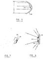
- Figure 5 shows that a light source 210 placed at the focus of a reflector parabolic 212 produces a light beam having a width L along the height of the parabolic reflector 212. If the reflector 212 is cylindrical, the width of the beam remains L but, on the vertical plane, the reflector acts like a flat mirror and produces a beam with large angle, as illustrated in Figures 6 and 7. Thus, if a linear bulb 210 is used as light source, the resulting beam will have the shape illustrated in Figure 7.
- Each of the parabolic units 201 can theoretically produce a beam of 180 °. In practice, the resulting beam is not effective over the whole. In addition, to be able to obtain satisfactory lighting and to have a minimum of shade, the lighting system 9 must be placed parallel to the axis of rotation 2 of the camera 1. As previously indicated, two units 201 are used, one at the top of lens 7 and one below lens 7 For be able to obtain a light beam of at least 180 °, each of these parabolic units is inclined at an angle of about 30 ° to the vertical, as shown in Figures 1 and 4.
- these are masked by a metal tab 214, placed in front of the bulb 210.
- the camera 1 is preferably powered by means of a battery (not shown). However, it could be powered by wire.
Landscapes
- Engineering & Computer Science (AREA)
- Multimedia (AREA)
- Signal Processing (AREA)
- Studio Devices (AREA)
- Stereoscopic And Panoramic Photography (AREA)
Abstract
Description
Claims (10)
- Caméra panoramique comprenant:un boítier (10) ayant un axe longitudinal (2) et comprenant une première partie (3) coaxiale audit axe et une deuxième partie (5) également coaxiale audit axe, cette deuxième partie (5) pouvant être entraínée en rotation autour dudit axe longitudinal (2) par rapport à la première partie (3),des moyens (100) pour entraíner en rotation la deuxième partie dudit boítier;une lentille (7) montée sur la deuxième partie (5) du boítier, ladite lentille étant orientée perpendiculairement et radialement à l'axe longitudinal (2);un capteur linéaire CCD (21) placé au foyer de la lentille (7) de façon à pouvoir recueillir les images transmises par la lentille (7), ledit capteur linéaire (21) ayant une entrée pour un signal de contrôle et une sortie de signal analogique représentant une ligne de l'image;un convertisseur analogique-numérique (27) relié au capteur linéaire (21) pour convertir le signal analogique provenant du capteur linéaire en information numérique, ledit convertisseur (27) ayant une entrée pour le signal analogique provenant du capteur linéaire, une entrée pour un signal de contrôle et une sortie pour l'information numérique;des moyens (51) pour stocker l'information numérique provenant du convertisseur analogique numérique;des moyens (150) pour coder l'azimut de ladite caméra ayant une sortie pour des données relatives à l'azimut; etun système de contrôle (35,37,39,41) pour contrôler la rotation du boítier (10), envoyer un signal de contrôle audit convertisseur analogique-numérique (27) pour numériser l'image et envoyer un signal aux moyens (51) pour stocker l'information numérique transmise par le convertisseur, de sorte que, lorsque ladite deuxième partie (5) est entraínée en rotation, le système de contrôle envoie d'une part un signal de contrôle au convertisseur analogique-numérique (27) à des intervalles réguliers pour indiquer audit convertisseur de numériser l'image et envoie d'autre part un signal aux moyens pour stocker l'information numérique de façon à stocker ladite information séquentiellement en incluant les données provenant desdits moyens pour coder l'azimut.
- Une caméra panoramique selon la revendication 1, caractérisée en ce que la lentille (7) est une lentille à grand angulaire.
- Une caméra panoramique selon la revendication I ou 2, caractérisée en ce qu'elle comprend en outre:
un système (9) d'éclairage rectiligne comprenant deux unités paraboliques (201) orientées parallèlement et radialement à l'axe longitudinal et placées au dessus et au dessous de la lentille. - Une caméra panoramique selon la revendication 1, 2 ou 3, caractérisée en ce que:ladite première partie (3) comprend en outre une tige (60) coaxiale audit axe longitudinal, ayant une partie supérieure et une partie inférieure; etla deuxième partie (5) dudit boítier est reliée à ladite première partie au moyen d'un roulement à billes (71) fixé à la partie inférieure de ladite tige.
- Une caméra panoramique selon la revendication 4, caractérisée en ce que les moyens (150) pour coder l'azimut comprennent:une roue d'azimut (151) fixée à la périphérie de la partie inférieure de ladite tige; etun codeur d'azimut (153) ayant une entrée reliée à la roue d'azimut et une sortie reliée au système de contrôle, pour pouvoir orienter la caméra par rapport à une direction prédéterminée et pour pouvoir coder l'image avec des données provenant dudit codeur d'azimut.
- Une caméra panoramique selon la revendication 1, 2, 3, 4 ou 5, caractérisée en ce que les moyens (100) pour entraíner en rotation la deuxième partie dudit boítier comprennent:un engrenage composé d'une première roue (101) coaxiale audit axe longitudinal, ayant un diamètre donné et une circonférence, ladite première roue étant fixée sur ladite première partie du boítier, et d'une deuxième roue (103) ayant un diamètre beaucoup plus petit que le diamètre de la première roue, pouvant voyager le long de la circonférence de ladite première roue (101), ladite deuxième roue (103) ayant une axe de rotation parallèle audit axe longitudinal; etun moteur électrique (105) activable par un signal de contrôle et ayant un axe de sortie relié à la deuxième roue pour entraíner en rotation ladite deuxième roue par rapport à ladite première roue, ledit moteur (105) étant fixé à la deuxième partie dudit boítier et ladite entrée pour un signal de contrôle provenant du système de contrôle.
- Une caméra panoramique selon la revendication 1, 2, 3, 4 ou 5, caractérisée en ce que lesdits moyens (100) pour entraíner en rotation la deuxième partie du boítier comprennent:un engrenage à roue (111) et à vis sans fin (113), ladite roue (111) étant coaxiale audit axe longitudinal et fixée à ladite première partie dudit boítier, ladite vis (113) sans fin étant fixée à un moteur (115) fixé sur ladite deuxième partie du boítier, ledit moteur (115) étant activable par un signal de contrôle provenant du système de contrôle.
- Une caméra panoramique selon la revendication 6 ou 7, caractérisée en ce que:le système de contrôle (35,37,39,41) comprend en outre une entrée pour commandes à distance;ladite tige est évidée, définissant un passage central, et comprend un câble coaxial à l'intérieur dudit passage central, ledit câble ayant une extrémité électriquement connectée à une bague collectrice située à la partie inférieure de ladite tige;le système de contrôle (35,37,39,41) étant également connecté à ladite bague collectrice.
- Une caméra panoramique selon la revendication 8, caractérisée en ce que le système de contrôle est un micro-ordinateur.
- Une caméra panoramique selon la revendication 9, caractérisée en ce que les moyens (51) pour stocker l'information numérique sont une unité de disque dur.
Applications Claiming Priority (2)
| Application Number | Priority Date | Filing Date | Title |
|---|---|---|---|
| CA002194002A CA2194002A1 (fr) | 1996-12-24 | 1996-12-24 | Camera electronique panoramique |
| CA2194002 | 1996-12-24 |
Publications (2)
| Publication Number | Publication Date |
|---|---|
| EP0851674A2 true EP0851674A2 (fr) | 1998-07-01 |
| EP0851674A3 EP0851674A3 (fr) | 1999-09-29 |
Family
ID=4159546
Family Applications (1)
| Application Number | Title | Priority Date | Filing Date |
|---|---|---|---|
| EP97403104A Withdrawn EP0851674A3 (fr) | 1996-12-24 | 1997-12-19 | Caméra électronique panoramique |
Country Status (3)
| Country | Link |
|---|---|
| US (1) | US6144406A (fr) |
| EP (1) | EP0851674A3 (fr) |
| CA (1) | CA2194002A1 (fr) |
Cited By (3)
| Publication number | Priority date | Publication date | Assignee | Title |
|---|---|---|---|---|
| EP0977425A1 (fr) | 1998-07-31 | 2000-02-02 | Bonnet Gerhard | Appareil et méthode de prise d'images panoramiques en couleurs |
| WO2001080550A3 (fr) * | 2000-04-13 | 2002-03-28 | Csir | Appareil photographique panoramique |
| EP1289317A4 (fr) * | 2000-03-31 | 2007-03-21 | Olympus Optical Co | Methode de postage de donnees d'images tridimensionnelles et procede de realisation d'une image tridimensionnelle |
Families Citing this family (24)
| Publication number | Priority date | Publication date | Assignee | Title |
|---|---|---|---|---|
| US6356296B1 (en) * | 1997-05-08 | 2002-03-12 | Behere Corporation | Method and apparatus for implementing a panoptic camera system |
| EP0977068A3 (fr) * | 1998-07-31 | 2000-04-19 | Loyal Port Company Limited | Dispositif d'inversion de l'image |
| US7129971B2 (en) * | 2000-02-16 | 2006-10-31 | Immersive Media Company | Rotating scan self-cleaning camera |
| US7224387B2 (en) * | 2002-01-09 | 2007-05-29 | Hewlett-Packard Development Company, L.P. | Method and apparatus for correcting camera tilt distortion in panoramic images |
| US7262789B2 (en) * | 2002-01-23 | 2007-08-28 | Tenebraex Corporation | Method of creating a virtual window |
| US6880987B2 (en) * | 2002-06-21 | 2005-04-19 | Quickset International, Inc. | Pan and tilt positioning unit |
| US7791638B2 (en) * | 2004-09-29 | 2010-09-07 | Immersive Media Co. | Rotating scan camera |
| US8018489B2 (en) * | 2005-02-04 | 2011-09-13 | Mccutchen David | Surveillance system |
| US20060268360A1 (en) * | 2005-05-12 | 2006-11-30 | Jones Peter W J | Methods of creating a virtual window |
| US20070126867A1 (en) * | 2005-12-02 | 2007-06-07 | Mccutchen David | High resolution surveillance camera |
| JP4682044B2 (ja) * | 2006-01-12 | 2011-05-11 | キヤノン株式会社 | 撮像装置 |
| US20070264004A1 (en) * | 2006-05-11 | 2007-11-15 | Daggett George D | Multiple image mosaic photograph camera mount and method |
| US8446509B2 (en) * | 2006-08-09 | 2013-05-21 | Tenebraex Corporation | Methods of creating a virtual window |
| CN101420525A (zh) * | 2007-10-26 | 2009-04-29 | 鸿富锦精密工业(深圳)有限公司 | 拍照装置及方法 |
| TWI383671B (zh) * | 2007-11-09 | 2013-01-21 | Hon Hai Prec Ind Co Ltd | 拍照裝置及方法 |
| MY147066A (en) * | 2007-11-09 | 2012-10-15 | Mimos Berhad | Apparatus and method for multiple-view panoramic imaging |
| US20090290033A1 (en) * | 2007-11-16 | 2009-11-26 | Tenebraex Corporation | Systems and methods of creating a virtual window |
| US8564640B2 (en) * | 2007-11-16 | 2013-10-22 | Tenebraex Corporation | Systems and methods of creating a virtual window |
| US8791984B2 (en) * | 2007-11-16 | 2014-07-29 | Scallop Imaging, Llc | Digital security camera |
| US20090160936A1 (en) * | 2007-12-21 | 2009-06-25 | Mccormack Kenneth | Methods and apparatus for operating a video camera assembly |
| WO2011037964A1 (fr) * | 2009-09-22 | 2011-03-31 | Tenebraex Corporation | Systèmes et procédés de correction d'image dans un système multicapteur |
| US20160065807A1 (en) * | 2014-09-03 | 2016-03-03 | L-3 Communications Cincinnati Electronics Corporation | Panoramic imaging systems using external rotating devices |
| CN205071148U (zh) | 2015-10-28 | 2016-03-02 | 杭州海康威视数字技术股份有限公司 | 一种全景拼接摄像机 |
| JP7154230B2 (ja) * | 2017-05-15 | 2022-10-17 | アウスター インコーポレイテッド | 輝度を増強した光学撮像送信器 |
Family Cites Families (7)
| Publication number | Priority date | Publication date | Assignee | Title |
|---|---|---|---|---|
| US4153917A (en) * | 1978-01-23 | 1979-05-08 | The United States Of America As Represented By The Secretary Of The Navy | Image stabilizer system for stop-action playback |
| JPS56152452U (fr) * | 1980-04-14 | 1981-11-14 | ||
| DE3223971C2 (de) * | 1982-06-26 | 1984-06-14 | Schäfter + Kirchhoff, 2000 Hamburg | Fernsehkamera für digitale On-line-Bildauswertung |
| GB2157526B (en) * | 1983-05-16 | 1986-08-28 | Barr & Stroud Ltd | Imaging systems |
| JP3021556B2 (ja) * | 1990-06-20 | 2000-03-15 | ソニー株式会社 | 映像情報処理装置とその方法 |
| JPH08275066A (ja) * | 1995-03-29 | 1996-10-18 | Toshiba Corp | パノラマカメラ |
| US6034716A (en) * | 1997-12-18 | 2000-03-07 | Whiting; Joshua B. | Panoramic digital camera system |
-
1996
- 1996-12-24 CA CA002194002A patent/CA2194002A1/fr not_active Abandoned
-
1997
- 1997-06-30 US US08/886,144 patent/US6144406A/en not_active Expired - Fee Related
- 1997-12-19 EP EP97403104A patent/EP0851674A3/fr not_active Withdrawn
Cited By (3)
| Publication number | Priority date | Publication date | Assignee | Title |
|---|---|---|---|---|
| EP0977425A1 (fr) | 1998-07-31 | 2000-02-02 | Bonnet Gerhard | Appareil et méthode de prise d'images panoramiques en couleurs |
| EP1289317A4 (fr) * | 2000-03-31 | 2007-03-21 | Olympus Optical Co | Methode de postage de donnees d'images tridimensionnelles et procede de realisation d'une image tridimensionnelle |
| WO2001080550A3 (fr) * | 2000-04-13 | 2002-03-28 | Csir | Appareil photographique panoramique |
Also Published As
| Publication number | Publication date |
|---|---|
| CA2194002A1 (fr) | 1998-06-24 |
| EP0851674A3 (fr) | 1999-09-29 |
| US6144406A (en) | 2000-11-07 |
Similar Documents
| Publication | Publication Date | Title |
|---|---|---|
| EP0851674A2 (fr) | Caméra électronique panoramique | |
| EP2614406B1 (fr) | Dispositif optique pour la capture d'images selon un champ de 360 ° | |
| EP0511101B1 (fr) | Procédé de modélisation d'un système de prise de vues et procédé et système de réalisation de combinaisons d'images réelles et d'images de synthèse | |
| FR2558971A1 (fr) | Appareil de formation d'images d'empreintes digitales | |
| EP2183633A2 (fr) | Dispositif de projection panoramique, et procede mis en oeuvre dans ce dispositif | |
| US6667772B1 (en) | Gimbal optical system for document image capture | |
| FR2513397A1 (fr) | Dispositif d'observation infrarouge | |
| FR2792488A1 (fr) | Dispositif d'emission d'images video numeriques | |
| FR2595151A1 (fr) | Appareil a balayage optique | |
| JPH11331520A (ja) | 回転画像ヘッドと回転式ミラ―とを備えた携帯型スキャナ | |
| EP4118479B1 (fr) | Procédé d'acquisition d'image d'un astre et appareil pour la mise en oeuvre du procédé | |
| FR2602885A1 (fr) | Procede de prises de vues permettant d'enregistrer des spheres visuelles et dispositif pour sa mise en oeuvre | |
| CN1183478C (zh) | 图象输入装置 | |
| CA2897978A1 (fr) | Lampe d'eclairage public exterieur a diodes electroluminescentes et lampadaire ou reverbere equipe d'une telle lampe | |
| EP3545262B1 (fr) | Système et procédé de numérisation tridimensionnelle d'un objet | |
| FR2593616A1 (fr) | Bague avec obturateur integre, en particulier pour prise de vues | |
| FR2830128A1 (fr) | Capteur photoelectrique avec des elements de capture de pixels disposes en cercles concentriques et dispositif d'acquisition d'images panoramiques comprenant ce capteur | |
| FR2580865A1 (fr) | Appareil d'imagerie thermique afocal | |
| EP1555506A1 (fr) | Dispositif de prise d'image assurant une mise au point indépendante de la position de l'objet | |
| EP0359634A1 (fr) | Episcope de conduite et d'observation jour et nuit pour véhicule blindé | |
| CN209841194U (zh) | 基于红外扫描的无人机输电线路山火勘测装置 | |
| EP1053636B1 (fr) | Procede d'acquisition ultra-rapide d'une sequence d'images au moyen d'un capteur matriciel a semi-conducteurs, type ccd, et dispositif pour la mise en oeuvre de ce procede | |
| EP1112653B1 (fr) | Camera cinevideo | |
| FR2599919A1 (fr) | Camera thermique a balayage vertical | |
| Larish | High-end digital photo cameras: Dicomed sees their continuing place |
Legal Events
| Date | Code | Title | Description |
|---|---|---|---|
| PUAI | Public reference made under article 153(3) epc to a published international application that has entered the european phase |
Free format text: ORIGINAL CODE: 0009012 |
|
| AK | Designated contracting states |
Kind code of ref document: A2 Designated state(s): AT BE CH DE DK ES FI FR GB GR IE IT LI LU MC NL PT SE |
|
| AX | Request for extension of the european patent |
Free format text: AL;LT;LV;MK;RO;SI |
|
| RIN1 | Information on inventor provided before grant (corrected) |
Inventor name: COTE, JEAN Inventor name: PELLETIER, JEAN-GUY Inventor name: GIRARD, PIERRE |
|
| PUAL | Search report despatched |
Free format text: ORIGINAL CODE: 0009013 |
|
| AK | Designated contracting states |
Kind code of ref document: A3 Designated state(s): AT BE CH DE DK ES FI FR GB GR IE IT LI LU MC NL PT SE |
|
| AX | Request for extension of the european patent |
Free format text: AL;LT;LV;MK;RO;SI |
|
| STAA | Information on the status of an ep patent application or granted ep patent |
Free format text: STATUS: THE APPLICATION HAS BEEN WITHDRAWN |
|
| 18W | Application withdrawn |
Withdrawal date: 20000322 |