EP0851701A2 - Kontrollverfahren zum Weiterreichen in schnurlosem ATM Netz - Google Patents
Kontrollverfahren zum Weiterreichen in schnurlosem ATM Netz Download PDFInfo
- Publication number
- EP0851701A2 EP0851701A2 EP97122792A EP97122792A EP0851701A2 EP 0851701 A2 EP0851701 A2 EP 0851701A2 EP 97122792 A EP97122792 A EP 97122792A EP 97122792 A EP97122792 A EP 97122792A EP 0851701 A2 EP0851701 A2 EP 0851701A2
- Authority
- EP
- European Patent Office
- Prior art keywords
- base station
- mobile terminal
- switch
- cell
- data
- Prior art date
- Legal status (The legal status is an assumption and is not a legal conclusion. Google has not performed a legal analysis and makes no representation as to the accuracy of the status listed.)
- Withdrawn
Links
Images











Classifications
-
- H—ELECTRICITY
- H04—ELECTRIC COMMUNICATION TECHNIQUE
- H04L—TRANSMISSION OF DIGITAL INFORMATION, e.g. TELEGRAPHIC COMMUNICATION
- H04L12/00—Data switching networks
- H04L12/54—Store-and-forward switching systems
- H04L12/56—Packet switching systems
- H04L12/5601—Transfer mode dependent, e.g. ATM
-
- H—ELECTRICITY
- H04—ELECTRIC COMMUNICATION TECHNIQUE
- H04Q—SELECTING
- H04Q11/00—Selecting arrangements for multiplex systems
- H04Q11/04—Selecting arrangements for multiplex systems for time-division multiplexing
- H04Q11/0428—Integrated services digital network, i.e. systems for transmission of different types of digitised signals, e.g. speech, data, telecentral, television signals
- H04Q11/0478—Provisions for broadband connections
-
- H—ELECTRICITY
- H04—ELECTRIC COMMUNICATION TECHNIQUE
- H04W—WIRELESS COMMUNICATION NETWORKS
- H04W36/00—Hand-off or reselection arrangements
- H04W36/0005—Control or signalling for completing the hand-off
- H04W36/0055—Transmission or use of information for re-establishing the radio link
- H04W36/0064—Transmission or use of information for re-establishing the radio link of control information between different access points
-
- H—ELECTRICITY
- H04—ELECTRIC COMMUNICATION TECHNIQUE
- H04L—TRANSMISSION OF DIGITAL INFORMATION, e.g. TELEGRAPHIC COMMUNICATION
- H04L12/00—Data switching networks
- H04L12/54—Store-and-forward switching systems
- H04L12/56—Packet switching systems
- H04L12/5601—Transfer mode dependent, e.g. ATM
- H04L2012/5603—Access techniques
- H04L2012/5604—Medium of transmission, e.g. fibre, cable, radio
- H04L2012/5607—Radio
-
- H—ELECTRICITY
- H04—ELECTRIC COMMUNICATION TECHNIQUE
- H04L—TRANSMISSION OF DIGITAL INFORMATION, e.g. TELEGRAPHIC COMMUNICATION
- H04L12/00—Data switching networks
- H04L12/54—Store-and-forward switching systems
- H04L12/56—Packet switching systems
- H04L12/5601—Transfer mode dependent, e.g. ATM
- H04L2012/5619—Network Node Interface, e.g. tandem connections, transit switching
-
- H—ELECTRICITY
- H04—ELECTRIC COMMUNICATION TECHNIQUE
- H04L—TRANSMISSION OF DIGITAL INFORMATION, e.g. TELEGRAPHIC COMMUNICATION
- H04L12/00—Data switching networks
- H04L12/54—Store-and-forward switching systems
- H04L12/56—Packet switching systems
- H04L12/5601—Transfer mode dependent, e.g. ATM
- H04L2012/5619—Network Node Interface, e.g. tandem connections, transit switching
- H04L2012/562—Routing
-
- H—ELECTRICITY
- H04—ELECTRIC COMMUNICATION TECHNIQUE
- H04L—TRANSMISSION OF DIGITAL INFORMATION, e.g. TELEGRAPHIC COMMUNICATION
- H04L12/00—Data switching networks
- H04L12/54—Store-and-forward switching systems
- H04L12/56—Packet switching systems
- H04L12/5601—Transfer mode dependent, e.g. ATM
- H04L2012/5625—Operations, administration and maintenance [OAM]
-
- H—ELECTRICITY
- H04—ELECTRIC COMMUNICATION TECHNIQUE
- H04L—TRANSMISSION OF DIGITAL INFORMATION, e.g. TELEGRAPHIC COMMUNICATION
- H04L12/00—Data switching networks
- H04L12/54—Store-and-forward switching systems
- H04L12/56—Packet switching systems
- H04L12/5601—Transfer mode dependent, e.g. ATM
- H04L2012/5629—Admission control
- H04L2012/563—Signalling, e.g. protocols, reference model
-
- H—ELECTRICITY
- H04—ELECTRIC COMMUNICATION TECHNIQUE
- H04L—TRANSMISSION OF DIGITAL INFORMATION, e.g. TELEGRAPHIC COMMUNICATION
- H04L12/00—Data switching networks
- H04L12/54—Store-and-forward switching systems
- H04L12/56—Packet switching systems
- H04L12/5601—Transfer mode dependent, e.g. ATM
- H04L2012/5678—Traffic aspects, e.g. arbitration, load balancing, smoothing, buffer management
- H04L2012/5679—Arbitration or scheduling
-
- H—ELECTRICITY
- H04—ELECTRIC COMMUNICATION TECHNIQUE
- H04W—WIRELESS COMMUNICATION NETWORKS
- H04W92/00—Interfaces specially adapted for wireless communication networks
- H04W92/16—Interfaces between hierarchically similar devices
- H04W92/20—Interfaces between hierarchically similar devices between access points
Definitions
- the present invention relates to a signaling framework for supporting mobility in a wireless ATM network. Specifically, the invention refers to wireless control protocols for handoff between base stations and mobile terminals.
- ATM technology is playing an increasingly important role in future broadband networks and it is expected that there will be an emergence of "wireless ATM” networks enabling multimedia access for mobile end systems. Consequently, mobility support in an ATM network assumes increasing importance.
- PCS Personal communication services
- broadband networking for delivery of multimedia information
- technologies for PCS and broadband communications have historically been developed somewhat independently, harmonization into a single architectural framework is motivated by an emerging need to extend multimedia services to portable terminals, as well as by service integration and operational efficiency considerations.
- ATM is viewed as a universal base technology for broadband networks. It is reasonable to consider of standard ATM services into next-generation microcellular wireless/PCS scenarios. D. Raychaudhuri and N. D. Wilson, in an article entitled "ATM-based Transport Architecture for Multiservices Wireless Personal Communication Networks", IEEE Journal on Selected Areas of Communications, vol. 12, no. 8, 1994, pp.
- the present invention concerns the related signaling, syntax and protocols required to support mobility in such a wireless ATM system. While some early work on the handoff aspects has been reported by A. Acampora and M. Nahchineh in an article entitled “An Architecture and Methodology for Mobile-Executed Handoff in Cellular ATM Networks", IEEE journal on Selected Areas of Communications, vol. 12, no. 8, pp. 1365-1375, 1994 and by L.V. Hauwemeiren et al in an article entitled “Requirements for Mobility Support in ATM", Proc. of Globecom, 1994, pp. 1691-1694, further conceptual developments is required to define a complete framework for handoff control in ATM.
- connection paths does not change during the life of a connection. This assumption is invalid when the terminal is a mobile terminal. In such cases, special handoff protocols are required.
- the present invention provides efficient handoff techniques to support mobility within an ATM network. As an ATM connection is handed off from a first base station to a second base station, there is either a partial path re-routing of the signal from the source to the second base station or there is a path extended to the second base station.
- U. S. Patent No. 5,487,065 entitled “Method and Apparatus for Supporting Mobile Communications in Asynchronous Transfer Mode Based Networks” describes an ATM based network where the handoff is distributed, as contrasted with a centralized network.
- a communication route is determined which includes a connection from a base station via a switching node.
- a connection tree is determined to include potential connection from other base stations to the switching node.
- a conventional portable telephone system which mainly handles a digitized audio signal.
- each user transmits a data stream at a period of 2 milliseconds.
- no fatal problem occurs even when the loss or duplication of data packets takes place over several periods. Therefore, no consideration is made in the conventional portable telephone system for a zero cell loss hand-off operation.
- a first preferred method is referred to as partial path re-routing. This method is based on removing a portion of the existing connection and adding a new sub-path from the point of detachment to the mobile terminal. After the mobile terminal is handed off, the portion of the existing connection from the handoff switch to the original mobile terminal is replaced by a new subpath from the handoff switch to the new mobile terminal which is created and spliced to the original connection from the source to the handoff switch.
- This protocol is described generally in an article by R. Yuan et al entitled "A Signaling and Control Architecture for Mobility Support in Wireless ATM Network", Proc. of ILC, June 1996.
- a second preferred method is referenced to as path extension. This method extends an active connection from the previous base station to the new base station. The method is that after handoff, the new connection includes the existing connection from the source to a mobile terminal followed by an additional sub-path (extension) from the previous base station to the new base station.
- the hand-off switch will often be called a cross over switch (COS) hereinafter.
- COS cross over switch
- a method for mobile-communications connections and routing in a network including base stations, a mobile terminal, a remote terminal switches, and datapath links.
- the method comprises the steps of establishing a communications connection from a remote terminal to a mobile terminal via a first datapath link including a first switch and a first base station, signaling from said mobile terminal to said first base station when a hand-off is to occur, signaling from said first base station to a second base station via a second datapath link including a second switch requesting a hand-off while establishing a second datapath link from aid first base station to said second base station via said first switch and said second switch, signaling from said second base station to said first base station that said second datapath link is established, and signaling from said first base station to said mobile terminal to change communications from said first base station to said second base station and sending data from said first base station to said second base station via said second datapath link.
- a wireless ATM communication method for use in a system which comprises a mobile terminal and a wired network communicable with the mobile terminal through an ATM cell, the method comprises the steps of inserting a specific OAM cell in a stream of user cells between the mobile terminal and the wired network when a hand-off procedure is initiated by the mobile terminal, and carrying out a hand-off operation by the use of the specific OAM cell.
- a wireless ATM communication method where the system comprises a base station which has a first datapath link to the mobile terminal and another base station which is to form a second datapath link to the above-mentioned mobile terminal, the hand-off operation is carried out by switching the first data path link to the second data path link, while the OAM cell inserting step is carried out at the mobile terminal and comprising the steps of producing a first OAM cell which is representative of the last cell transmitted before the hand-off operation, inserting, as the specific OAM cell, the first OAM cell in the user cell stream, producing a second OAM cell which is representative of the first ATM cell transmitted after the hand-off operation, and inserting, as the specific OAM cell, the second OAM cell in the user cell stream.
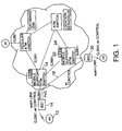
- a network diagram that illustrates the various network components and functions that may comprise an ATM network, that supports mobility. That is, a wireless ATM network intended to support integrated broadband services to mobile terminals.
- the mobile terminal is a complete ATM end system that is capable of supporting multimedia applications. It uses a standard ATM signaling protocol (Q.2931, ATM Forum UNI3.1) for connection establishment between end system.
- the wireless link between a mobile terminal (MT) 12 and base station (BS) 14 provides the desired ATM transport services to the mobile terminal.
- a mobility enhanced signaling protocol based on the ITU recommendation Q.2931 (termed Q.2931) is used by the MT, BS and MSS (mobility support switches) 16 to support handoff related functions.
- wireless control protocols are used between base stations 14, 20 to facilitate wireless resource management and sequential cell delivery during handoffs. This custom protocol is supported via permanent virtual circuits (PVC) 18 between neighboring base stations 14 and 20.
- PVC permanent virtual circuits
- the location registration and resolution functions are performed by the location servers (LS) 22 and database (DB) systems 24 which coexists with the network switch element.
- the location management is decoupled from the connection management system. Such decoupling permits the independent operation and optimization of location updates scheme. It also enables efficient support of the connectionless data service in the network.
- the architecture is based on an integration of the wireless and mobility specific functions into the standard ATM protocol stack.
- the user plane and control plane are shown in Fig. 2 where the wireless MAC (medium access control) 30, wireless DLC (data link control) 32 and wireless control 34 represent new layers added for wireless ATM support.
- the function of wireless MAC and wireless DLC layers is to provide a standard ATM transport service across the shared/unreliable wireless (radio) channel.
- the wireless control protocol supports management functions at these layers, while interfacing with higher layer (ATM) control functions.
- the end-to-end virtual connection is constructed by link-by-link VCs connected through different network switches.
- the handoff of a mobile terminal between different base stations is the dynamic reconfiguration of the end-to-end VCs under the constraint of QOS requirements of the connections.
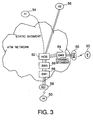
- the end-to-end VCs are separated into two segments: the static and dynamic segments (note that in the case of connection between two MTs, the end-to-end VC may be separated into three segments, but from the perspective of one MT during re-configuration, the two segments scenario still applies).
- Such an arrangement is shown in Fig.
- a mobile terminal MT 50 has three active connections from two remote terminals (RT) 54, 56, one from RT1 54 and two from RT2 56.
- RT remote terminals
- RT1 54 remote terminals
- RT2 56 remote terminals
- these connections are reconfigured by creating three new segments from the handoff switch (HOS) 62 to BS2 60 via switch SW2 54, and changing the VC routing table at the HOS 62.
- HOS handoff switch
- the Handoff Switch which will be also referred to as a cross over switch is the mobility supporting switch that anchors the entire handoff process.
- HOS Handoff Switch
- BS1 58 and BS2 60 the HOS 62 establishes a group of new dynamic segments and then connects them with the original static segments.
- a general inter-switch handoff arrangement is shown in Fig. 4.
- the mobile terminal 50 migrates away from BS1 58 and towards the cell coverage area of BS2 60, the mobile terminal listens to the beacon signals from both base stations.
- the mobile terminal can suggest when to initiate a handoff from BS1 to BS2 based on its measurements of the BS beacons.
- the mobile terminal sends an HO_INDICATION signal to the base station using the wireless control protocol between MT50 and BS 58.
- the HO_INDICATION signal includes multiple potential handoff candidates.
- BS1 58 Upon receiving the HO_INDICATION signal from the mobile terminal, BS1 58 uses the wireless control protocol between base stations to contact the handoff candidate base stations through the PVC established between base stations. In this example, the primary candidate BS2 60 acknowledges the availability of resources.
- BS1 After receiving the acknowledgement from BS2, BS1 sends an HO_REQUEST message to the handoff switch.
- the selection of the HOS can be based on the route optimization for the multiple connections and various QOS requirements. It is also possible to have multiple HOSs handle multiple connections. However, for implementation simplicity, it is assumed that there is only one HOS.
- the HOS then establishes a datapath to the targeted base station via the fixed network signaling scheme (Q.2931). After the alternate datapath is established, the HOS sends a HO_REQ_ACK message to BS1 58.
- BS1 sends a HO_START message to the mobile terminal through the wireless control channel.
- it sends a RT_CHANGE signal to the switch to instruct the switch to change the datapath from the original to the newly established connections via switch 64 instead of via switch 66.
- the mobile terminal After receiving the HO_START from BS1 58, the mobile terminal changes its operating frequency and starts communicating through BS2 60.
- New base station 60 (BS2) identification. Both the mobile terminal 50 and the base stations 58, 60 can coordinate the selection. Usually, a BS beacon serves the purpose of base station identification and SIR/BER measurement.
- the handoff switch can be selected based on the route optimization from multiple connections and a series of QOS considerations.
- the easiest selection is the current switch serving the mobile terminal. This is the switch where all the connections to the mobile terminal transit. The possibility that another mobile terminal within the same base station coverage can establish a connection to MT 50 directly through the base station without involving the switch is excluded.
- New mobile segments establishment A group of new mobile segments are established together between HOS 62 and BS2 60, and BS2 can allocate the wireless resources for the mobile terminal before actual handoff.
- the HOS 62 reroutes the connections by connecting the original static segments with the new mobile segments.
- BS1 58 instructs the mobile terminal to switch to the new base station.
- the old base station transfers the wireless datalink states information to the new base station. This guarantees the in-sequence delivery of ATM cells.
- route Optimization can be treated separately from the handoff process, as long as the HOS provides reasonable robustness to avoid obvious loops.
- SW1 66 acts as the HOS
- the signaling flow during the handoff process is shown in Fig. 5.
- Several signal messages are used to achieve the MT handoff between the two base stations.
- current ATM signaling protocol standard does not have the mobility support functions.
- extensions to the ATM signaling protocols are disclosed to facilitate mobility support in an ATM network.
- Table 1 is a list of the extension signals, their functionalities and the information elements (IE).
- HO_REQUEST Request HOS to initiate the handoff process MT address, new BS address, multiple connection identifiers HO_REQ_ACK Acknowledges HO_REQUEST MT address, new BS information, MT, address and new ID, multiple connection identifiers M_SETUP Establish multiple connections MT address, new BS address, multiple connection identifiers and parameters M_CALL_PROC Indicate the reception of M_SETUP MT address, multiple connection identifiers M_CONNECT Acknowledges M_SETUP MT address, new ID, multiple connection identifiers and parameters RT_CHANGE Request change of routing table at HOS Multiple connection identifiers, MT address RT_CHANGE_ACK Acknowledges RT_CHANGE MT address M_RELEASE Request releasing multiple single hop connections Multiple connection identifiers M_RELEASE_ACK Acknowledges M_RELEASE Multiple connection identifiers RENEGOTIATION Renegotiation service/QOS parameter Connection
- the HO_REQUEST message transits through SW3 68. If SW3 68 is a regular ATM network switch that does not support mobility extensions, it is difficult for the HO_REQUEST to function transparently across SW3. If SW3 has mobility support extensions, it can interpret the message and issue a similar HO_REQUEST to HOS 62 with different connection identifier and call reference values. It is assumed that HOS 62 communicates directly with BS1 58, and all network switches support mobility.
- Another signaling function of importance in the mobile arrangement is that of service parameter and QOS specification and renegotiation in the presence of heterogeneous/variable radio channel bandwidth.
- the available service parameters may be lower than that requested in the original connection request message. Most often this is due to radio channel limitations.
- a suitable "fallback" mechanism which sets up a connection with the highest available bandwidth parameters is needed. This type of fallback function is useful in conventional fixed network scenarios as well, although it is not specified in the current ATM Forum UNI specification.
- the provision of a CONNECT (..., new service parameters, ...) message in response to a SETUP (..., service parameters, ...) message is possible.
- QOS specification is another important aspect to be considered in mobile ATM.
- Current ATM signaling provides for QOS specification in the standard SETUP message, but does not specify how this QOS budget is to be allocated between each segment of the route.
- a larger QOS degradation budget i.e. CDV, CLR or CTD
- CDV, CLR or CTD QOS degradation budget
- MAC and DLC protocols used on the access link. For example, if a total delay budget of 30 ms is specified, it might be appropriate to allocate 20 ms to the radio link and 10 ms to the fixed network segment, thus permitting the use of relatively powerful DLC modes for low CLR.
- the method (referring to Fig. 3) is based on the idea that when a mobile end host MT moves from base stations BS1 58 to BS2 60, then an existing connection between MT 50 and a remote terminal RT 54, 56 isrerouted at an intermediate switch 62, called the handoff or handover switch (HOS).
- HOS handoff or handover switch
- the connection isrerouted at the HOS 62 by adding a subpath from HOS to BS2 60 and deleting the subpath from HOS to BS1 58, followed by a transfer of buffered cells from BS1 to BS2.
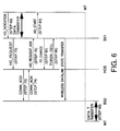
- FIG. 6 shows the signaling messages during handoff.
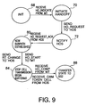
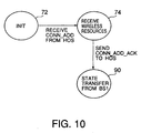
- Figs. 7, 8, 9 and 10 are state transition diagrams for the mobile terminal to be handed off, the handoff switch, an initial base station (BS1) and a subsequent base station (BS2), respectively. The same numerals are used for the same sequential step in each figure.
- BS1 sends a HO_REQUEST (conn-id) message to HOS (step 70) to initiate rerouting of the connection identified by conn-id, using appropriate extensions to the NNI signaling standards.
- HO_REQUEST conn-id
- the HOS sends a connection setup signaling message CONN_ADD (conn_id) to BS2 (step 72), creating the subpath from HOS to BS2 for the connection conn_id.
- CONN_ADD connection setup signaling message
- BS2 responds with a CONN_ACK (conn_id) signaling message to HOS (step 74), if the subpath was setup successfully.
- BS2 also reserves buffer space to hold incoming cells on the subpath. The buffer space is released after the handoff is complete.
- HOS sends a HO_REQUEST_ACK (conn_id) signaling message to BS1 (step 76).
- MT sends a HO_INDICATE signaling message to BS1(step 68).
- BS 1 Upon receiving the HO_REQUEST_ACK message, BS 1 sends a HO_START (conn_id) signaling message to MT (step 80), stops transmitting data cells, and sends a RT_CHANGE signal to HOS (step 80).
- HO_START conn_id
- MT switches its operating frequency to that of BS2 after receiving HO_START from BS1 (step 82). It can optionally send a HO_COMPLETE message to BS1 before switching frequencies (step 84).
- HOS After receiving the RT_CHANGE message, HOS changes its hardware routing tables so that the cells on connection are routed to BS2 via the newly established subpath (step 86) and sends a OAM ("token") cell on the existing subpath towards BS1 (step 86).
- OAM token
- BS2 "splices" the received datalink state with its buffered state, and transmits cells to MT1 in sequence (step 90).
- FIGs. 11 to 16 show the signaling message during handoff.
- Lazy optimization refers to the fact that the path can be optimized by eliminating duplicate or unnecessary path by removing loops after handoff.
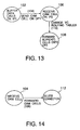
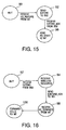
- Figs. 12, 13, 14, 15 and 16 are state transition diagrams for the mobile terminal to be handed off, the loop removal at looping point (Hand Off Switch), the loop removal at the initial base station (BS1), the initial base station (BS1) itself, and the subsequent base station (BS2), respectively.
- Hand Off Switch loop removal at looping point
- BS1 initial base station
- BS1 initial base station
- BS1 initial base station
- BS1 initial base station
- BS1 initial base station
- BS2 subsequent base station
- the path extension with lazy optimization handoff scheme is based on two principal concepts. First, extending an existing connection (to the mobile MT) from the previous base station (BS1) to the current base station (BS2) after a cell switch and second, removal of loops in the augmented connection performed using in-band OAM cells in a lazy manner after the MT has started to send and receive cells from BS2.
- MT sends a HO_INDICATION signaling message (step 90) to BS1 indicating BS2 to be its next base station.
- BS1 sends an EXTEND (conn_id) signaling message to BS2 (step 92), thereby extending the current connection with BS1.
- EXTEND EXTEND
- BS2 replies with an EXTEND_ACK (conn_id) if the connection would be successfully extended (step 94). At this point BS2 allocates buffer space to hold incoming cells on the extended connection, until MT switches its operating frequency to that of BS2.
- BS1 then stops transmitting cells on its wireless link to MT (step 96), asking it to switch its operating frequency to that of BS2.
- MT switches its frequency and sends a HO_TERMINATE signaling message to BS2 (step 98).
- BS2 starts to forward cells from the extended connection on the wireless link to MT (step 100).
- a second sequence of steps is executed after the handoff is completed to remove potential loops in the augmented connection.
- a switch detects that there is a looping point in the augmented connection by examining entries in the connection routing tables. If there are two entries for the same connection, then the switch is a looping point.
- the switch HOS is a looping point since its connection table contains two distinct entries for the same connection conn_id: ⁇ IP1, OP1 ⁇ , ⁇ IP2, OP2 ⁇ .
- the first entry has its input port (IP1) as the link between RT and HOS and the output port (OP1) as the link from the HOS to BS1.
- the second entry has the link between BS1 and HOS as its input port (IP2), and the link between HOS and BS2 as its output port (OP2). See, for example, Fig. 3.
- OP1 and IP2 are the same link, but in general that need not be the case.
- the looping point is detected during the process of path extension, i.e. when a switch receives and processes the EXTEND message.
- the loop elimination procedure is initiated by the looping point after the MT has begun to receive ATM cells from the new base station. This can be inferred by the looping point (the hand-off switch, HOS) by observing when ATM cells begin to flow across both pairs of input-output ports, corresponding to the connection conn_id.
- the looping point the hand-off switch, HOS
- the looping point begins to buffer cells on the input port (IP1) corresponding to the beginning of the loop (step 102); sends at OAM cell on the output port (OP1), corresponding to IP1 (step 104); receives the OAM cell back on IP2 (step 106); forwards the buffered ATM cells onto OP2 (step 108); change its hardware routing tables (VPI/VCI entries) to route incoming ATM cells on IP1 onto OP2 (step 110); and merges the two connection table (software) entries into a single entry ⁇ IP1, OP2 ⁇ .
- each intermediate switch in the loop receives the OAM cell (sent by the looping point) it forwards the OAM cell on the corresponding output port. Then, it deletes that connection (step 112) and releases all resources used for the connection.
- Fig. 17 is a diagram of a typical mobile ATM network architecture. It consists of fixed terminal 1, ATM switches 2, 3 ad 4, radio port base stations 5, 6, 7 and 8, with corresponding coverage areas 10, 11, 12 and 13, and mobile terminal (MT) 9.
- fixed terminal 1 ATM switches 2, 3 ad 4
- radio port base stations 5, 6, 7 and 8 with corresponding coverage areas 10, 11, 12 and 13, and mobile terminal (MT) 9.
- MT mobile terminal
- MT 9 is a complete ATM end system that is capable of supporting multimedia applications, such as an NEC Versa laptop with a wireless ATM card.
- multimedia applications such as an NEC Versa laptop with a wireless ATM card.
- An example of a wireless ATM card is described in an article by Cesar Johnston entitled, "A Network Interface Card for Wireless ATM Networks", Proceedings of IEEE PIMRC, 1996. This article is incorporated herein by reference.
- MT 9 uses a standard ATM signaling protocol (Q.2931, ATM Forum UNI3.1) for connecting between end systems.
- a typical base station is an ATM switch with a radio port for transmitting cells on the wireless link.
- ATM switches 2, 3 and 4 such as 2.4 Gbps NEC model 55 running ATM Forum's UNI and NNI signaling, plus mobility extensions, are interconnected as shown via wireline links, with the exception of MT 9, which is interconnected to the network via a wireless link with the base stations.
- the connection between the ATM switches, base stations and fixed terminal are standard ATM wireline links, such as TAXI or SONET.
- the connection between MT 9 and base stations 7 and 8 are standard radio/wireless ATM links.
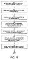
- MT 9 or base station 7 determines that a handoff is necessary, for example, when MT 9 starts to move outside coverage area 12 of base station 7 and into coverage area 13 of base station 8, MT 9 sends a proposed extended signaling message HANDOFF REQUEST signal to base station 7, requesting a connection handoff to another base station (step 100).
- Methods for choosing a new base station are well known in cellular telephone systems. For example, it is assumed that base station 8 will be chosen as the new base station (step 110).
- an ATM switch that will act as a crossover switch namely, a handoff switch is selected (step 120).
- the method for selecting the ATM switch to act as crossover switch is also not essential to this invention, however, a method for selecting a crossover switch is described in an article by C. K. Toh entitled, "Performance Evaluation of Crossover Switch Discovery for Wireless ATM LANs", Proceedings of Infocom, 1996. This article is incorporated herein by reference. For this example, it is assumed that ATM switch 2 will be chosen to act as the crossover switch. Base station 7 then forwards the HANDOFF REQUEST signal to crossover switch 2 (step 130).
- crossover switch 2 After receiving the HANDOFF REQUEST signal, crossover switch 2 sends an outband SETUP signal to base station 8 (step 140). When a virtual channel is established between crossover switch 2 and base station 8, base station 8 sends an outband CONNECT signal to crossover switch 2 (steps 150, 160). Note that outband signals are sent on a separate signaling channel, while inband signals are typically operation and maintenance (OAM) cells sent along the connection path.
- OAM operation and maintenance
- crossover switch 2 After receiving CONNECT signal, crossover switch 2 sends an outband HANDOFF RESPONSE signal to MT 9 (step 179).
- MT 9 confirms the receipt of this signal by sending an outband HANDOFF CONFIRM signal to crossover switch 2 via base station 7 and switches 4 and 3 (step 180).
- crossover switch 2 After crossover switch 2 receives the HANDOFF CONFIRM signal, it introduces an inband end-of-stream (EOS) operations and maintenance (OAM) cell into the old path 14 to MT 9 (step 190).
- EOS-OAM in effect "flushes" all of the data cells that are in transit from crossover switch 2 to MT 9 on the old path 14, thus preventing the loss of data cells.
- Crossover switch 2 the changes its virtual channel routing table so that the end-to-end datapath from crossover switch 2 to MT 9 now follows the new path 15 (step 200).
- Crossover switch 2 also immediately stops all data cell transmission to MT 9 and starts buffering, in order, the data cells to be sent to MT 9 in a local buffer (step 210). This, in effect, release the old path 14 in this direction for subsequent data cells, however, the old path 14 is still in place in the opposite direction from MT 9 to crossover switch 2 to accommodate incoming data cells from MT 9.
- MT 9 After MT 9 receives the EOS-OAM cell from crossover switch 2, it returns it to crossover switch 2 (step 220). MT 9 then immediately stops all transmission of data cells to crossover switch 2 and starts buffering, in order, the data cells to be sent to crossover switch 2 in a local buffer (step 230). The return trip of the EOS-OAM cell in effect "flushes" all of the data cells that are in transit from MT 9 to crossover switch 2 on the old path 14, thus preventing the loss of data cells.
- MT 9 After MT 9 returns the EOS-OAM cell to crossover switch 2, it sends an outband HANDOFF JOIN signal to base station 8 to establish a wireless connection and complete the new path 15 (step 240). After the connection is established, base station 8 sends an outband HANDOFF JOIN COMPLETE signal to MT 9 (steps 250, 260). MT 9 then sends an inband start-of-stream (SOS) OAM cell to crossover switch 2 over the new path 15 (step 270). MT 9 then sends the data cells it had been buffering, in a first in, first out order, stops buffering data cells and resumes normal transmission of data cells (step 280).
- SOS start-of-stream
- crossover switch 2 After crossover switch 2 receives the EOS-OAM from MT 9, it changes its virtual channel routing table so that the end-to-end datapath from MT 9 to crossover switch 2 now follow the new path 15 and sends and outband HANDOFF RELEASE signal to MT 9 which releases the old path 14 in this direction (step 290). Note that this step can take place before any of steps 240-280, depending on when crossover switch 2 receives the EOS-OAM cell.
- crossover switch 2 After crossover switch 2 receives the SOS-OAM cell from MT 9, it returns the SOS-OAM cell followed by the data cells it had been buffering, in a first in, first out order, and stops buffering and resumes normal transmission of data cells (step 300). Note that transmission of the data cells crossover switch 2 receives from MT 9 after the SOS-OAM cell can not take place until after crossover switch 2 receives the EOS-OAM cell referred to in step 280. If this EOS-OAM cell has not yet been received, crossover switch 2 buffers, in order, the data cells it receives from MT 9 over the new path until the EOS-OAM is received, at which time the buffered cells can be released in a first in, first out order.
- the buffering of data cells can be performed at the new base station 8 instead of at crossover switch 2.
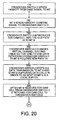
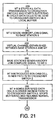
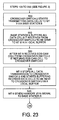
- steps 100-200 of the handoff process remain the same (refer to Figs. 10 to 22). The remaining steps differ from the process described above as follows.
- crossover switch 2 After crossover switch 2 receives the EOS-OAM cell and changes its virtual channel routing table so that the end-to-end datapath from crossover switch 2 to MT 9 now follows the new path 15 (step 200), crossover switch 2 starts transmitting data cells to MT 9 via base station 8 (step 500). Base station 8 then starts buffering, in order, data cells to be sent to MT 9 in a local buffer (step 510).
- MT 9 After MT 9 receives the EOS-OAM cell from crossover switch 2, it returns the EOS-OAM cell to base station 8 via crossover switch 2 (step 520). MT 9 then immediately stops all transmission of data cells to crossover switch 2 and starts buffering, in order, data cells to be sent to crossover switch 2 in a local buffer (step 530). The return trip of the EOS-OAM cell in effect "flushes" all of the data cells that are in transit from MT 9 to crossover switch 2 on the old path 14, thus preventing the loss of data cells.
- MT 9 After MT 9 returns the EOS-OAM cell to base station 8, it sends an outband HANDOFF JOIN signal to base station 8 to establish a wireless connection and complete the new path 15 (step 540). After the connection is established, base station 8 sends outband HANDOFF JOIN COMPLETE signal to MT 9 (steps 550, 560). MT 9 then introduces an inband start-of-stream (SOS) OAM cell to base station 8 over the new path 15 (step 570). MT 9 then sends the data cells it had been buffering, in a first in, first out order, steps buffering data cells and resumes normal transmission of data cells (step 580).
- SOS start-of-stream
- crossover switch 2 After crossover switch 2 receives the EOS-OAM from MT 9, it changes its virtual channel routing table so that the end-to-end datapath from MT 9 to crossover switch 2 now follows the new path 15 and sends an outband HANDOFF RELEASE signal to MT 9 which releases the old path 14 in this direction (step 590). Note that this step can take place before any of steps 540-580, depending on when crossover switch 2 receives the EOS-OAM cell.
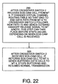
- base station 8 After base station 8 receives the SOS-OAM cell from MT 9, it returns it, followed by the data cells it had been buffering, in a first in, first out order, and stops buffering and resumes normal transmission of data cells (step 300). Note that trasmission of the data cells base station 8 receives from MT 9 after the SOS-OAM cell can not take place until after crossover switch 2 receives the EOS-OAM cell referred to in step 590. If this EOS-OAM cell has not yet been received, base station 8 buffers the data cells it receives from MT 9 over the new path until the EOS-OAM is received, at which time the buffered cells can be released in a first in, first out order.
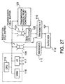
- FIG. 27 illustration is schematically made about a mobile terminal which is for use in a wireless ATM communication system according to this invention.
- the mobile terminal illustrated is a mobile terminal for transmission and reception of ATM cells and includes a transmitter 110 and a receiver 111 both of which are coupled to an antenna through a duplexer 112.
- the illustrated mobile terminal has a terminal controller which is composed of a central processing unit (CPU) 115, a memory (MEM) 116, and an input/output (I/O) interface 117.
- the memory 116 and the I/O interface 117 are connected to the CPU 115 through a bus.
- the receiver 111 is connected to a reception ATM cell buffer 120 which is in turn connected to the CPU 115 through the bus.
- a transmission ATM cell buffer 121 and an EOS detector 122 are connected between the CPU 115 and the transmitter 110.
- the EOS detector 122 serves to detect an EOS-OAM.
- the illustrated transmission ATM cell buffer 121 and the EOS detector 122 are connected to a transmission buffer read controller 123.
- the CPU 115 included in the terminal controller sends a hand-off control OAM cell (namely, an EOS-OAM cell representative of the last cell of a cell stream) to the transmission cell buffer 121.
- the EOS-OAM cell is transmitted to a base station (not shown in this figure) through the EOS detector 122 and the transmitter 110.
- the EOS-OAM is detected by the EOS detector 122 which notifies the transmission buffer read controller 123 of detection of the EOS-OAM. Responsive to this notification, the transmission buffer read controller 123 stops a readout operation of the transmission buffer 122.
- an SOS-OAM which is given from the CPU 115 is arranged as a leading cell or the first cell at an ATM cell stream which is to be sent from the mobile terminal to the base station and which is successively stored in the transmission cell buffer 121.
- control information is not sent to the transmission cell buffer 121 and is directly given to the transmitter 110.
- the SOS-OAM when the SOS-OAM is transmitted from the base station to indicate a leading cell of a cell stream, the SOS-OAM is sent to the CPU 115 through the receiver 111 and the reception cell buffer 120. Responsive to the SOS-OAM, the CPU 115 judges that the cell stream may be restarted and indicates a start of transmission to the transmission buffer read controller 123. Supplied with this indication, the transmission buffer read controller 123 makes the transmission cell buffer 121 transmit, through the transmitter 110, the SOS-OAM and thereafter the following ATM cell stream stored in the transmission cell buffer 121.
- crossover switch may be formed in a manner similar to that illustrated in Fig. 27.
Landscapes
- Engineering & Computer Science (AREA)
- Computer Networks & Wireless Communication (AREA)
- Signal Processing (AREA)
- Mobile Radio Communication Systems (AREA)
Priority Applications (1)
| Application Number | Priority Date | Filing Date | Title |
|---|---|---|---|
| EP02007225A EP1223779A3 (de) | 1996-12-24 | 1997-12-23 | Kontrollverfahren zum Weiterreichen in schnurlosem ATM Netz |
Applications Claiming Priority (7)
| Application Number | Priority Date | Filing Date | Title |
|---|---|---|---|
| US08/773,738 US5974036A (en) | 1996-12-24 | 1996-12-24 | Handoff-control technique for wireless ATM |
| US773738 | 1996-12-24 | ||
| US08/948,612 US6023461A (en) | 1997-10-10 | 1997-10-10 | Handoff method for an ATM wireless network wherein both the switch and the mobile buffer cells and the mobile controls when the handoff will occur |
| US948612 | 1997-10-10 | ||
| JP09321737A JP3075347B2 (ja) | 1996-12-24 | 1997-11-21 | 無線atmネットワークにおけるハンドオフ方法 |
| JP32173797 | 1997-11-21 | ||
| JP321737/97 | 1997-11-21 |
Related Child Applications (1)
| Application Number | Title | Priority Date | Filing Date |
|---|---|---|---|
| EP02007225A Division EP1223779A3 (de) | 1996-12-24 | 1997-12-23 | Kontrollverfahren zum Weiterreichen in schnurlosem ATM Netz |
Publications (2)
| Publication Number | Publication Date |
|---|---|
| EP0851701A2 true EP0851701A2 (de) | 1998-07-01 |
| EP0851701A3 EP0851701A3 (de) | 1999-12-22 |
Family
ID=27339870
Family Applications (1)
| Application Number | Title | Priority Date | Filing Date |
|---|---|---|---|
| EP97122792A Withdrawn EP0851701A3 (de) | 1996-12-24 | 1997-12-23 | Kontrollverfahren zum Weiterreichen in schnurlosem ATM Netz |
Country Status (1)
| Country | Link |
|---|---|
| EP (1) | EP0851701A3 (de) |
Cited By (11)
| Publication number | Priority date | Publication date | Assignee | Title |
|---|---|---|---|---|
| WO2003055105A1 (en) * | 2001-12-12 | 2003-07-03 | Samsung Electronics Co., Ltd. | Method for performing a handoff in a mobile communication system |
| US6625583B1 (en) * | 1999-10-06 | 2003-09-23 | Goldman, Sachs & Co. | Handheld trading system interface |
| US7107240B1 (en) | 1999-10-06 | 2006-09-12 | Goldman Sachs & Co. | Order centric tracking system and protocol for communications with handheld trading units |
| US7165040B2 (en) | 1999-05-19 | 2007-01-16 | I.D. Systems, Inc. | System and method for managing remotely and distantly located assets |
| CN1307576C (zh) * | 2001-12-19 | 2007-03-28 | 汤姆森特许公司 | 在移动网络和无线局域网之间切换移动终端的方法和设备 |
| EP1422883A4 (de) * | 2001-08-27 | 2008-07-02 | Ntt Docomo Inc | Weiterreichungssteuervorrichtung, basisstation, netzkanten-router, relay-router, funkendgerätevorrichtung, mobilkommunikationssystem und weiterreichungssteuerverfahren |
| US7656271B2 (en) | 2002-01-09 | 2010-02-02 | I.D. Systems, Inc. | System and method for managing a remotely located asset |
| US7656273B2 (en) | 2005-03-01 | 2010-02-02 | I.D. Systems, Inc. | Mobile portal for RFID luggage handling applications |
| US7667573B2 (en) | 2005-03-01 | 2010-02-23 | I.D. Systems, Inc. | Mobile portal for RFID applications |
| US8370268B2 (en) | 1999-05-19 | 2013-02-05 | I.D. Systems, Inc. | Systems and methods for remote vehicle rental with remote vehicle access |
| US10290052B1 (en) | 2009-08-28 | 2019-05-14 | Jpmorgan Chase Bank, N.A. | ATM exception processing system and method |
-
1997
- 1997-12-23 EP EP97122792A patent/EP0851701A3/de not_active Withdrawn
Non-Patent Citations (2)
| Title |
|---|
| MITTS H. ET AL: "Lossless handover for wireless ATM", PROCEEDINGS OF THE SECOND ANNUAL INTERNATIONAL CONFERENCE ON MOBILE COMPUTING AND NETWORKING, 11 November 1996 (1996-11-11) - 12 November 1996 (1996-11-12), WHITE PLAINS, NY, US, pages 85 - 96, XP001048563 * |
| YUAN R. ET AL: "A SIGNALING AND CONTROL ARCHITECTURE FOR MOBILITY SUPPORT IN WIRELESS ATM NETWORKS", PROCEEDINGS OF ICC, vol. 1, 23 June 1996 (1996-06-23), pages 478 - 484 * |
Cited By (27)
| Publication number | Priority date | Publication date | Assignee | Title |
|---|---|---|---|---|
| US7356494B2 (en) | 1999-05-19 | 2008-04-08 | I.D. Systems, Inc. | Robust wireless communications system architecture and asset management applications performed thereon |
| US7876197B2 (en) | 1999-05-19 | 2011-01-25 | I.D. Systems, Inc. | Mobile asset data management system |
| US7898388B2 (en) | 1999-05-19 | 2011-03-01 | I.D. Systems, Inc. | Mobile asset data management system |
| US7911320B2 (en) | 1999-05-19 | 2011-03-22 | I.D. Systems, Inc. | Mobile asset data management system |
| US7165040B2 (en) | 1999-05-19 | 2007-01-16 | I.D. Systems, Inc. | System and method for managing remotely and distantly located assets |
| US7171381B2 (en) | 1999-05-19 | 2007-01-30 | I.D. Systems, Inc. | System architecture and communications for an asset management system |
| US8370268B2 (en) | 1999-05-19 | 2013-02-05 | I.D. Systems, Inc. | Systems and methods for remote vehicle rental with remote vehicle access |
| US8676670B2 (en) | 1999-05-19 | 2014-03-18 | I.D. Systems, Inc. | Mobile asset data management system |
| US8725596B2 (en) | 1999-05-19 | 2014-05-13 | I.D. Systems, Inc. | Mobile asset data management system |
| US8533105B1 (en) | 1999-10-06 | 2013-09-10 | Goldman, Sachs & Co. | Order centric tracking system and protocol for communications with handheld trading units |
| US6625583B1 (en) * | 1999-10-06 | 2003-09-23 | Goldman, Sachs & Co. | Handheld trading system interface |
| US7107240B1 (en) | 1999-10-06 | 2006-09-12 | Goldman Sachs & Co. | Order centric tracking system and protocol for communications with handheld trading units |
| EP1422883A4 (de) * | 2001-08-27 | 2008-07-02 | Ntt Docomo Inc | Weiterreichungssteuervorrichtung, basisstation, netzkanten-router, relay-router, funkendgerätevorrichtung, mobilkommunikationssystem und weiterreichungssteuerverfahren |
| US7424295B2 (en) | 2001-08-27 | 2008-09-09 | Ntt Docomo, Inc. | Handover control apparatus, base station, edge router, relay router, radio terminal unit, mobile communication system, and handover control method |
| CN100345396C (zh) * | 2001-12-12 | 2007-10-24 | 三星电子株式会社 | 用于在移动通信系统中执行越区切换的方法 |
| WO2003055105A1 (en) * | 2001-12-12 | 2003-07-03 | Samsung Electronics Co., Ltd. | Method for performing a handoff in a mobile communication system |
| US7065362B2 (en) | 2001-12-12 | 2006-06-20 | Samsung Electronics Co., Ltd. | Method for performing a handoff in a mobile communication system |
| CN1307576C (zh) * | 2001-12-19 | 2007-03-28 | 汤姆森特许公司 | 在移动网络和无线局域网之间切换移动终端的方法和设备 |
| US7707054B2 (en) | 2002-01-09 | 2010-04-27 | I.D. Systems, Inc. | System and method for remotely managing maintenance operations associated with an asset |
| US7656271B2 (en) | 2002-01-09 | 2010-02-02 | I.D. Systems, Inc. | System and method for managing a remotely located asset |
| US7786844B2 (en) | 2005-03-01 | 2010-08-31 | I.D. Systems, Inc. | Mobile portal for RFID applications |
| US8120467B2 (en) | 2005-03-01 | 2012-02-21 | I.D. Systems, Inc. | Mobile portal for RFID applications |
| US7683760B2 (en) | 2005-03-01 | 2010-03-23 | I.D. Systems, Inc. | Mobile portal for RFID applications |
| US7667573B2 (en) | 2005-03-01 | 2010-02-23 | I.D. Systems, Inc. | Mobile portal for RFID applications |
| US7656273B2 (en) | 2005-03-01 | 2010-02-02 | I.D. Systems, Inc. | Mobile portal for RFID luggage handling applications |
| US10290052B1 (en) | 2009-08-28 | 2019-05-14 | Jpmorgan Chase Bank, N.A. | ATM exception processing system and method |
| US11948188B2 (en) | 2009-08-28 | 2024-04-02 | Jpmorgan Chase Bank, N.A. | ATM exception processing system and method |
Also Published As
| Publication number | Publication date |
|---|---|
| EP0851701A3 (de) | 1999-12-22 |
Similar Documents
| Publication | Publication Date | Title |
|---|---|---|
| US5974036A (en) | Handoff-control technique for wireless ATM | |
| Yuan et al. | A signaling and control architecture for mobility support in wireless ATM networks | |
| US6023461A (en) | Handoff method for an ATM wireless network wherein both the switch and the mobile buffer cells and the mobile controls when the handoff will occur | |
| US5528583A (en) | Method and apparatus for supporting mobile communications in mobile communications networks | |
| US5487065A (en) | Method and apparatus for supporting mobile communications in asynchronous transfer mode based networks | |
| US6553015B1 (en) | High speed switching of communications links without interrupting ATM cell traffic | |
| CA2181283C (en) | Method for call establishment and rerouting in mobile computing networks | |
| FI109503B (fi) | Pakettien menetyksen estäminen pakettipohjaisen tietoliikenneverkon handoverissa sekä handovermenetelmä | |
| JP3444220B2 (ja) | ハンドオフ制御方法、スイッチングノード、移動無線端末、及び記録媒体 | |
| Yuan et al. | Mobility support in a wireless ATM network | |
| JP4206616B2 (ja) | 呼接続管理装置 | |
| EP0976268B1 (de) | Wegoptimierung zur vermeidung von schleifen in einem paketvermittelten telekommunikationsnetz | |
| Yu et al. | Connection architecture and protocols to support efficient handoffs over an ATM/B-ISDN personal communications network | |
| Pollini et al. | Handover protocols between metropolitan area networks | |
| JPH08186580A (ja) | 通信システム | |
| EP1223779A2 (de) | Kontrollverfahren zum Weiterreichen in schnurlosem ATM Netz | |
| Chrysostomou et al. | A survey of wireless ATM handover issues | |
| Li et al. | Handoff control in wireless ATM networks: An experimental study | |
| KR100413191B1 (ko) | 이동통신망에서의 소프트 핸드오버 경로 제어 방법 | |
| Salah et al. | A two-phase inter-switch handoff scheme for wireless ATM networks | |
| Jiang et al. | Microcellular handover in wireless ATM | |
| KR100231706B1 (ko) | 핸드오프 전용의 에이티엠 스위칭 기능을 갖는 무선 에이티엠 액세스 포인트 | |
| KR100297596B1 (ko) | 무선비동기전송방식(watm) 네트워크에서의 핸드오버 시그널링 방법 | |
| Yuan et al. | Mobility support in a wireless ATM | |
| Takahashi et al. | A center‐controlled dynamic rerouting scheme for fast and reliable handover in mobile ATM networks |
Legal Events
| Date | Code | Title | Description |
|---|---|---|---|
| PUAI | Public reference made under article 153(3) epc to a published international application that has entered the european phase |
Free format text: ORIGINAL CODE: 0009012 |
|
| AK | Designated contracting states |
Kind code of ref document: A2 Designated state(s): DE FI |
|
| AX | Request for extension of the european patent |
Free format text: AL;LT;LV;MK;RO;SI |
|
| PUAL | Search report despatched |
Free format text: ORIGINAL CODE: 0009013 |
|
| AK | Designated contracting states |
Kind code of ref document: A3 Designated state(s): AT BE CH DE DK ES FI FR GB GR IE IT LI LU MC NL PT SE |
|
| AX | Request for extension of the european patent |
Free format text: AL;LT;LV;MK;RO;SI |
|
| 17P | Request for examination filed |
Effective date: 19991117 |
|
| AKX | Designation fees paid |
Free format text: DE FI |
|
| 17Q | First examination report despatched |
Effective date: 20011011 |
|
| STAA | Information on the status of an ep patent application or granted ep patent |
Free format text: STATUS: THE APPLICATION HAS BEEN WITHDRAWN |
|
| 18W | Application withdrawn |
Withdrawal date: 20021014 |