EP0851992B1 - Radiateur et installation de chauffage - Google Patents
Radiateur et installation de chauffage Download PDFInfo
- Publication number
- EP0851992B1 EP0851992B1 EP96929124A EP96929124A EP0851992B1 EP 0851992 B1 EP0851992 B1 EP 0851992B1 EP 96929124 A EP96929124 A EP 96929124A EP 96929124 A EP96929124 A EP 96929124A EP 0851992 B1 EP0851992 B1 EP 0851992B1
- Authority
- EP
- European Patent Office
- Prior art keywords
- heat
- container
- heat storage
- heater according
- heater
- Prior art date
- Legal status (The legal status is an assumption and is not a legal conclusion. Google has not performed a legal analysis and makes no representation as to the accuracy of the status listed.)
- Expired - Lifetime
Links
- 238000010438 heat treatment Methods 0.000 title claims abstract description 41
- 238000009434 installation Methods 0.000 title claims abstract description 5
- 238000005338 heat storage Methods 0.000 claims abstract description 54
- 239000012530 fluid Substances 0.000 claims abstract description 29
- 239000007787 solid Substances 0.000 claims abstract description 7
- 239000004020 conductor Substances 0.000 claims abstract description 5
- 238000004891 communication Methods 0.000 claims abstract description 3
- XLYOFNOQVPJJNP-UHFFFAOYSA-N water Substances O XLYOFNOQVPJJNP-UHFFFAOYSA-N 0.000 claims description 13
- 239000010949 copper Substances 0.000 claims description 9
- 229910052802 copper Inorganic materials 0.000 claims description 8
- 239000007788 liquid Substances 0.000 claims description 4
- 238000003860 storage Methods 0.000 claims description 4
- 239000004579 marble Substances 0.000 claims description 3
- 239000000463 material Substances 0.000 claims description 2
- 230000000063 preceeding effect Effects 0.000 claims 5
- 150000001879 copper Chemical class 0.000 claims 1
- 239000000446 fuel Substances 0.000 claims 1
- 238000012432 intermediate storage Methods 0.000 claims 1
- 239000003570 air Substances 0.000 description 20
- 239000002184 metal Substances 0.000 description 16
- 229910052751 metal Inorganic materials 0.000 description 16
- RYGMFSIKBFXOCR-UHFFFAOYSA-N Copper Chemical compound [Cu] RYGMFSIKBFXOCR-UHFFFAOYSA-N 0.000 description 7
- 230000005855 radiation Effects 0.000 description 7
- 239000013529 heat transfer fluid Substances 0.000 description 4
- 239000003921 oil Substances 0.000 description 4
- 238000001816 cooling Methods 0.000 description 2
- 230000017525 heat dissipation Effects 0.000 description 2
- 239000011810 insulating material Substances 0.000 description 2
- 241000446313 Lamella Species 0.000 description 1
- 150000004996 alkyl benzenes Chemical class 0.000 description 1
- 239000012080 ambient air Substances 0.000 description 1
- 238000009835 boiling Methods 0.000 description 1
- 230000001419 dependent effect Effects 0.000 description 1
- 238000010586 diagram Methods 0.000 description 1
- 230000005611 electricity Effects 0.000 description 1
- 150000002148 esters Chemical class 0.000 description 1
- 230000002349 favourable effect Effects 0.000 description 1
- 239000002803 fossil fuel Substances 0.000 description 1
- 238000009413 insulation Methods 0.000 description 1
- 238000004519 manufacturing process Methods 0.000 description 1
- 125000001997 phenyl group Chemical group [H]C1=C([H])C([H])=C(*)C([H])=C1[H] 0.000 description 1
- 230000001105 regulatory effect Effects 0.000 description 1
- 229920002545 silicone oil Polymers 0.000 description 1
- 239000004449 solid propellant Substances 0.000 description 1
- 238000013022 venting Methods 0.000 description 1
Images



Classifications
-
- F—MECHANICAL ENGINEERING; LIGHTING; HEATING; WEAPONS; BLASTING
- F24—HEATING; RANGES; VENTILATING
- F24H—FLUID HEATERS, e.g. WATER OR AIR HEATERS, HAVING HEAT-GENERATING MEANS, e.g. HEAT PUMPS, IN GENERAL
- F24H7/00—Storage heaters, i.e. heaters in which the energy is stored as heat in masses for subsequent release
- F24H7/002—Storage heaters, i.e. heaters in which the energy is stored as heat in masses for subsequent release using electrical energy supply
-
- F—MECHANICAL ENGINEERING; LIGHTING; HEATING; WEAPONS; BLASTING
- F24—HEATING; RANGES; VENTILATING
- F24H—FLUID HEATERS, e.g. WATER OR AIR HEATERS, HAVING HEAT-GENERATING MEANS, e.g. HEAT PUMPS, IN GENERAL
- F24H7/00—Storage heaters, i.e. heaters in which the energy is stored as heat in masses for subsequent release
- F24H7/02—Storage heaters, i.e. heaters in which the energy is stored as heat in masses for subsequent release the released heat being conveyed to a transfer fluid
- F24H7/04—Storage heaters, i.e. heaters in which the energy is stored as heat in masses for subsequent release the released heat being conveyed to a transfer fluid with forced circulation of the transfer fluid
- F24H7/0408—Storage heaters, i.e. heaters in which the energy is stored as heat in masses for subsequent release the released heat being conveyed to a transfer fluid with forced circulation of the transfer fluid using electrical energy supply
- F24H7/0433—Storage heaters, i.e. heaters in which the energy is stored as heat in masses for subsequent release the released heat being conveyed to a transfer fluid with forced circulation of the transfer fluid using electrical energy supply the transfer medium being water
-
- F—MECHANICAL ENGINEERING; LIGHTING; HEATING; WEAPONS; BLASTING
- F28—HEAT EXCHANGE IN GENERAL
- F28D—HEAT-EXCHANGE APPARATUS, NOT PROVIDED FOR IN ANOTHER SUBCLASS, IN WHICH THE HEAT-EXCHANGE MEDIA DO NOT COME INTO DIRECT CONTACT
- F28D1/00—Heat-exchange apparatus having stationary conduit assemblies for one heat-exchange medium only, the media being in contact with different sides of the conduit wall, in which the other heat-exchange medium is a large body of fluid, e.g. domestic or motor car radiators
- F28D1/02—Heat-exchange apparatus having stationary conduit assemblies for one heat-exchange medium only, the media being in contact with different sides of the conduit wall, in which the other heat-exchange medium is a large body of fluid, e.g. domestic or motor car radiators with heat-exchange conduits immersed in the body of fluid
- F28D1/04—Heat-exchange apparatus having stationary conduit assemblies for one heat-exchange medium only, the media being in contact with different sides of the conduit wall, in which the other heat-exchange medium is a large body of fluid, e.g. domestic or motor car radiators with heat-exchange conduits immersed in the body of fluid with tubular conduits
- F28D1/053—Heat-exchange apparatus having stationary conduit assemblies for one heat-exchange medium only, the media being in contact with different sides of the conduit wall, in which the other heat-exchange medium is a large body of fluid, e.g. domestic or motor car radiators with heat-exchange conduits immersed in the body of fluid with tubular conduits the conduits being straight
-
- F—MECHANICAL ENGINEERING; LIGHTING; HEATING; WEAPONS; BLASTING
- F28—HEAT EXCHANGE IN GENERAL
- F28D—HEAT-EXCHANGE APPARATUS, NOT PROVIDED FOR IN ANOTHER SUBCLASS, IN WHICH THE HEAT-EXCHANGE MEDIA DO NOT COME INTO DIRECT CONTACT
- F28D20/00—Heat storage plants or apparatus in general; Regenerative heat-exchange apparatus not covered by groups F28D17/00 or F28D19/00
- F28D20/0056—Heat storage plants or apparatus in general; Regenerative heat-exchange apparatus not covered by groups F28D17/00 or F28D19/00 using solid heat storage material
-
- H—ELECTRICITY
- H05—ELECTRIC TECHNIQUES NOT OTHERWISE PROVIDED FOR
- H05B—ELECTRIC HEATING; ELECTRIC LIGHT SOURCES NOT OTHERWISE PROVIDED FOR; CIRCUIT ARRANGEMENTS FOR ELECTRIC LIGHT SOURCES, IN GENERAL
- H05B3/00—Ohmic-resistance heating
- H05B3/40—Heating elements having the shape of rods or tubes
- H05B3/42—Heating elements having the shape of rods or tubes non-flexible
- H05B3/48—Heating elements having the shape of rods or tubes non-flexible heating conductor embedded in insulating material
- H05B3/50—Heating elements having the shape of rods or tubes non-flexible heating conductor embedded in insulating material heating conductor arranged in metal tubes, the radiating surface having heat-conducting fins
-
- Y—GENERAL TAGGING OF NEW TECHNOLOGICAL DEVELOPMENTS; GENERAL TAGGING OF CROSS-SECTIONAL TECHNOLOGIES SPANNING OVER SEVERAL SECTIONS OF THE IPC; TECHNICAL SUBJECTS COVERED BY FORMER USPC CROSS-REFERENCE ART COLLECTIONS [XRACs] AND DIGESTS
- Y02—TECHNOLOGIES OR APPLICATIONS FOR MITIGATION OR ADAPTATION AGAINST CLIMATE CHANGE
- Y02E—REDUCTION OF GREENHOUSE GAS [GHG] EMISSIONS, RELATED TO ENERGY GENERATION, TRANSMISSION OR DISTRIBUTION
- Y02E60/00—Enabling technologies; Technologies with a potential or indirect contribution to GHG emissions mitigation
- Y02E60/14—Thermal energy storage
-
- Y—GENERAL TAGGING OF NEW TECHNOLOGICAL DEVELOPMENTS; GENERAL TAGGING OF CROSS-SECTIONAL TECHNOLOGIES SPANNING OVER SEVERAL SECTIONS OF THE IPC; TECHNICAL SUBJECTS COVERED BY FORMER USPC CROSS-REFERENCE ART COLLECTIONS [XRACs] AND DIGESTS
- Y02—TECHNOLOGIES OR APPLICATIONS FOR MITIGATION OR ADAPTATION AGAINST CLIMATE CHANGE
- Y02E—REDUCTION OF GREENHOUSE GAS [GHG] EMISSIONS, RELATED TO ENERGY GENERATION, TRANSMISSION OR DISTRIBUTION
- Y02E70/00—Other energy conversion or management systems reducing GHG emissions
- Y02E70/30—Systems combining energy storage with energy generation of non-fossil origin
Definitions
- the invention relates to a radiator with a chamber for flow through Heat transfer medium, which has connections to a heating medium circuit, wherein preferably the chamber at least partially on a solid heat storage core is present. Furthermore, the invention relates to a heating system with an inventive Radiators using solar energy.
- Radiators of this and similar types are used, for example, in Hot water central heating systems are used, the heating source of which is gas heaters, oil Solid fuel furnaces, but also solar panels.
- a radiator which has a fixed Has heat storage core through which there is a meandering heating tube register extends through which hot water flows as a heat transfer medium.
- the Heat storage core is interspersed with hollow air ducts that extend vertically extend through the radiator and are open at the top and bottom, being at their upper opening can be closed with sliders.
- This Air duct pipes are penetrated by the heating pipe register and serve to Ambient air can flow from bottom to top through the radiator and thus Heat convection is generated.
- radiators generally consist of a jacket made of sheet metal with the largest possible outer surface, through the interior of which by Heated heat transfer medium flows through the heat source, thereby transferring its heat to the Releases the radiator jacket and is cooled down and returned to the heating source.
- the radiator jacket has only low heat storage capacity.
- the inflow of heat transfer medium to the radiator is generally thermostatically controlled intermittently, so that Radiators constantly undergo a considerable heating and cooling cycle subject to.
- the present invention provides a solution to the problem outlined Providing a radiator, which is characterized in that it also has a has containers made of heat-conducting material that can be filled with heat storage fluid, through which the chamber extends at least partially, the chamber and the Containers in thermally conductive relationship with each other without fluid communication stand.
- This radiator according to the invention thus has a large interior Heat storage mass, which is heated by the heat transfer medium in the heating circuit and then gradually releases its stored heat to the environment.
- the temperature of the heat storage mass inside the radiator can be adjusted manually or controlled by a thermostat, as well as - but independently of the former - the Heat emission from the radiator.
- Heat storage mass in the first case Appropriately water or an organic heat storage fluid as Heat storage mass can be used, but in the second case fireclay, marble or the like can be given preference as a heat storage core, in particular in the case of residential units that are not occupied for a long time, such as second homes with solar panels to prevent frost damage is advantageous.
- the container for heat storage fluid and the solid Heat storage core can also be used in combination, with delivery and Assembly of the radiator the container for heat storage fluid is empty and only after completed assembly is filled.
- the container preferably has heat storage fluid further closable openings for venting and emptying.
- the radiator according to the invention is suitable for installation in all known Hot water central heating as well as for use in solar collector heating Circulation pumps.
- the chamber for the flow of heat transfer medium can according to one Embodiment of the invention can be designed as a copper strip heat exchanger the container for heat storage medium and / or the heat storage core enforced, whereby a very good heat transfer to the heat storage fluid and or or the heat storage core is guaranteed.
- a wall of the container for heat storage fluid defines at least part of an air flow channel in the radiator. Thereby there the heat storage fluid gradually transfers its heat to that in the air flow channel flowing air and thus heats the surrounding space by convection.
- the cross section of the air flow channel through at least one manually operable or temperature-dependent controllable throttle valve is changeable.
- the warmed air in the flow channel is intended to transmit its heat to the convection heat give up surrounding space.
- Heating the wall of the flow channel and especially heat radiation through the heated flow channel wall outside may be undesirable if the radiator is close to an exterior wall of a house is arranged. In this case, it is expedient if the air flow channel is on its surface facing the radiator outside with a heat insulation layer is provided.
- Heat storage fluid heat storage oil
- Solid Heat storage core is fireclay, marble or the like in question.
- the volume of the container for Heat storage fluid that of the chamber for the flow of heat transfer medium considerably, in particular by at least three times.
- the invention also relates to a heating system comprising one or more Radiator according to the invention, on the one hand with a supply and return a heat source that runs on fossil fuels or electricity, and on the other hand is connected to at least one solar collector, wherein Heat source and solar collector (s) can be operated separately or in combination.
- a buffer store for temporary storage is also advantageous in this heating system excess heated heat transfer medium in the heating circuit interposed.
- FIG. 1 shows one in the drawings Radiator according to the invention in perspective
- Figure 2 the same inventive Radiator in cross section
- Figure 4 shows a detail of the radiator of Figures 1 and 2 in plan view
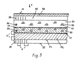
- Figure 5 a another embodiment of the radiator according to the invention
- Fig.6 a Function circuit of a heating system with a radiator according to the invention.
- the radiator 1 according to the invention in FIG. 1 generally has a cuboid shape and rests on legs 2, which are the supply air supply (as indicated by arrow 3) Allow bottom of radiator.
- the supply air passes through inside the radiator Channels up, heating it up and finally on the top of the radiator as heated exhaust air (arrow 4) leaves the radiator 1 through slots 5.
- At the Outside of the radiator are metal strips 6 to increase the Radiation area provided. The number and size of these metal strips can vary Subject to variation.
- the heat radiated from the outer surfaces of the radiator is symbolized by arrows W.
- a hot water supply connection 8 and one Water drainage 9 complete the radiator.
- One at the top of the Radiator opening air flow channel 55 can through a flap 57 are closed, which are attached to the radiator with a hinge 58 and therefore is pivotable.
- the position of the flap 57 can either be adjusted by hand be regulated or automatically controlled depending on the temperature.
- the heating element 1 is therein shown in cross section. It consists of a metal plate 23 which has an outer surface represents the radiator and on the outside of metal strips 6 to increase the Radiation area are arranged.
- the metal plate 23 is thermally conductive on one Heat storage layer 20 on.
- the heat storage layer 20 consists of hardened liquid refractory. Are in it a plurality of vertical heat exchanger tubes 50 one Cast copper strip heat exchanger. These heat exchanger tubes 50 also enforce a container 51 for heat storage fluid attached to the solid Heat storage layer 20 adjoins.
- the container 51 for heat storage fluid is on its remote from the fireclay core Wall defining part of an air flow channel 55 with fins 56 provided that protrude into the air flow channel 55 for better heat dissipation.
- the Wall of the container 51 and its fins 56 consist of good heat conductivity Material.
- the air flow channel becomes on the opposite side of the container 51 Side delimited by a layer 54 of heat insulating material, at the A metal plate 12 is arranged on the outside. Furthermore, in the container 51 for Heat storage fluid and 20 thermostats are provided in the heat storage layer be.
- the container 51 is with a closable opening, not shown Heat storage fluid can be filled, the filling only after the expedient
- the radiator is installed. In most cases it serves as a heat storage fluid Water, but an organic heat storage medium can also be used.
- an organic heat storage medium can also be used.
- paraffins, alkylbenzenes, phenyl compounds, high-boiling Esters and silicone oils are used.
- FIG 3 is an advantageously used in the radiator according to the invention
- Copper strip heat exchanger 59 shown.
- This consists of a supply pipe 61, a discharge pipe 60 and a plurality of parallel, spatially apart spaced heat exchanger tubes 50, the supply pipe 61 and the Connect the discharge pipe 60 communicating so that a heating medium through the Supply pipe, the heat exchanger pipes and the discharge pipe can flow.
- the Walls of the heat exchanger are made of copper, which are individual pipes ultrasonically welded.
- Elongated copper strips 62 welded to the effectiveness of the heat emission increase the environment.
- a dimensioning example for a radiator according to the invention with the external dimensions of 100 x 75 x 23 cm, lamella widths of 3 and 2 cm, and surfaces of the strips 6 of 600 cm 2 per strip. This results in a total area of all heat-radiating surfaces of 9.6 m 2 , which can be equated with the radiating surface of a low-temperature underfloor heating, so that a surface temperature of the radiator of 40 ° C is sufficient for heating a living space with 10 m 2 of floor space.
- the container for heat storage fluid is dimensioned with 100 x 75 x 10 cm, which results in a filling quantity of 75 1, the firebrick layer has the dimensions 100 x 75 x 6 cm. Since the density of fireclay is approx.
- the fireclay layer therefore has a mass of 81 kg.
- the storage heater according to the invention has a transport weight of less than 100 kg and can therefore be transported and installed by two fitters. After filling with heat storage fluid, however, the heat storage mass is almost doubled.
- the heat exchanger advantageously used in the radiator has 24 heat exchanger tubes with a length of 50 cm and a diameter of 12 mm, twelve of which are arranged in the container 51 and twelve in the firebrick layer.
- the filling volume of all 24 heat exchanger tubes is thus 1.36 1, with the supply and discharge lines for the heat exchanger results in a total filling volume of 1.5 1. This small filling quantity enables a drastic reduction in the amount of heating medium in the heating circuit.
- FIG. 4 shows a special configuration of the top of the radiator 1, in which a Cover 63 forms the top surface of the radiator, the cover over the Metal strips 6 protrudes and has a radiation film.
- the lid is from the Tops of the firebrick core and the container for the liquid Heat storage medium spaced so that there is an air gap between them, which in Connection to the flap, not shown, arranged in the lid Control of the convection current ensures a better convection current.
- the lid is drawn transparently, although it is in Reality is made of metal.
- the radiator according to the invention is heated by the heat transfer medium is in turn heated in a gas boiler, oil heating, etc., after reaching the Desired core or jacket outer temperature of the radiator thermostat-controlled throttled the supply of the heat transfer medium into the Cu heat exchanger or is switched off after the temperature has dropped below a predetermined value to be resumed.
- FIG. 5 there is a second embodiment of one Radiator 1 according to the invention shown in cross section.
- This consists of a Metal plate 25, which is an outer surface of the radiator and on the Outside metal strips 6 are arranged to increase the radiation area.
- the Metal plate 25 is located parallel to another metal plate 23, which bears against a fireclay layer 22 in a heat-conducting manner.
- the space between the metal plates 23 and 25 is bridged by fins 24, which as Thermal bridge acting connected to both the plate 23 and the plate 25 are.
- the slats 24 are also used to enlarge the Heat radiation surface.
- first fireclay layer 22 Adjacent to the metal plate 23 is a first fireclay layer 22 and adjoining it is a second layer of chamotte 20. Between these two Fireclay layers is an electrical resistance heating mat 21 arranged with Direct current can be operated from solar cells.
- the fireclay layer 20 consists of hardened liquid refractory. There are a number of vertical ones in it Cast heat exchanger tubes 50 of a copper strip heat exchanger. This Heat exchanger tubes 50 also pass through a container 51 for Heat transfer fluid adjacent to the chamotte layer 20, with between Container 51 and fireclay layer 20 a second electrical resistance heating mat 17th is arranged, which can be operated with alternating current from the general power grid.
- the container 51 for heat transfer fluid is on the heating mat 17th opposite wall, which defines part of an air flow channel 55 with Provided fins 56, the better heat dissipation in the air flow channel 55th protrude.
- the wall of the container 51 and its slats 56 are made of good thermally conductive material.
- the air flow channel becomes on the container 51st opposite side of a layer 54 of heat insulating material limited, on the outside of which a metal plate 12 is arranged.
- thermostats 52 and 53 provided in Container 51 for heat transfer fluid and in the chamotte layer 20 thermostats 52 and 53 provided.
- the container 51 is closable via a seal, not shown Opening can be filled with heat transfer fluid.
- FIG. 6 a circuit diagram of a heating system with a Radiator 1 according to the invention described.
- the inflow of this radiator is stopped with a conventional heating source 40, which is operated with gas, oil, etc. in Connection and is supplied with hot water via this line, which after passing of the radiator is returned to the heating source 40.
- the Radiator 1 also with the hot water flow of a solar panel 30 in Connection, with a return from the radiator drain to Solar panel inflow is present.
- the radiator 1 is thus on two different heating circuits connected, in combination or separately can be operated. Excess hot water from the solar panel can be in buffer storage or a heat exchanger for the production of domestic water be directed.
- radiators according to the embodiment 5 can also use solar cells to generate direct current to operate the electrical resistance heating elements can be provided in the radiators.
Landscapes
- Engineering & Computer Science (AREA)
- General Engineering & Computer Science (AREA)
- Thermal Sciences (AREA)
- Mechanical Engineering (AREA)
- Physics & Mathematics (AREA)
- Chemical & Material Sciences (AREA)
- Combustion & Propulsion (AREA)
- Central Heating Systems (AREA)
- Heat-Pump Type And Storage Water Heaters (AREA)
- General Induction Heating (AREA)
- Buildings Adapted To Withstand Abnormal External Influences (AREA)
- Yarns And Mechanical Finishing Of Yarns Or Ropes (AREA)
- Pipe Accessories (AREA)
- Steam Or Hot-Water Central Heating Systems (AREA)
- Resistance Heating (AREA)
Claims (14)
- Radiateur ayant une chambre à être traversée par un cours d'agent caloporteur, pourvue de raccords à un cycle d'agent de chauffage, la chambre étant préférablement au moins partiellement contiguë à un coeur accumulateur de chaleur (20) solide, caractérisé en ce que le radiateur (1) comprend en outre un récipient (51) de matière conductrice de chaleur, qui peut être chargé de fluide accumulateur de chaleur et dans lequel la chambre (50, 59) s'étend au moins partiellement, la chambre (50, 59) et le récipient (51) ayant un rapport de conduction thermique sans communication de fluide.
- Le radiateur selon la revendication 1, caractérisé en ce que la chambre à être traversée par un cours d'agent caloporteur est formée comme échangeur thermique à lame de cuivre (59), traversant le récipient (51) pour fluide accumulateur de chaleur et/ou le coeur accumulateur de chaleur (20).
- Le radiateur selon l'une des revendications 1 et 2, caractérisé en ce que son surface est pourvu de plaques (25) d'une matière bonne conductrice de chaleur, qui sont de préférence agrandies par des ailettes (6).
- Le radiateur selon l'une des revendications 1 à 3, caractérisé en ce qu'une paroi du récipient (51) pour fluide accumulateur de chaleur définit au moins une partie d'un passage de courant d'air (55) dans le radiateur (1).
- Le radiateur selon la revendication 4, caractérisé en ce que la section transversale du passage de courant d'air (55) peut être changée par au moins un volet de réglage (57) qui peut être actionné manuellement ou commandé selon la température.
- Le radiateur selon la revendication 4 ou 5, caractérisé en ce que le passage de courant d'air (55) est pourvu d'une couche d'isolation thermique (54) à sa surface dirigée vers l'extérieur du radiateur.
- Le radiateur selon l'une des revendications précédantes, caractérisé en ce que le coeur accumulateur de chaleur (20) solide est composé de chamotte ou de marbre.
- Le radiateur selon l'une des revendication précédantes, caractérisé en ce que le fluide accumulateur de chaleur est de l'eau ou un liquide organique accumulateur de chaleur.
- Le radiateur selon l'une des revendications précédantes, caractérisé en ce que le récipient (51) pour fluide accumulateur de chaleur est pourvu d'au moins un orifice qui peut être fermé et sert pour le remplir, le ventiler ou l'évacuer.
- Le radiateur selon l'une des revendications précédantes, caractérisé en ce que le volume du récipient (51) pour fluide accumulateur de chaleur est considérablement supérieur à celui de la chambre (50, 59) à être traversée par un cours d'agent caloporteur, en particulier au moins trois fois plus grand.
- Le radiateur selon l'une des revendications précédantes, caractérisé en ce qu'au moins un élément de chauffage ohmique (17, 21) est en outre prévu, arrangé au récipient (51) pour fluide accumulateur de chaleur et/ou au coeur accumulateur de chaleur (20) ou bien là-dedans.
- Le radiateur selon la revendication 11, caractérisé en ce que l'au moins un élément de chauffage ohmique (17, 21) peut être actionné alternativement par courant continu, préférablement obtenu par des cellules solaires, ou par courant alternatif venant du réseau général.
- Installation de chauffage, comprenant un ou plusieurs radiateurs selon l'une des revendications 1 à 12, qui est/sont relié(s), par une conduite d'arrivée et un retour, d'une part à une source de chauffage (40) opérée avec des combustibles fossiles ou du courant, et d'autre part à au moins un collecteur solaire (30), la source de chauffage (40) et le(s) collecteur(s) solaire(s) (30) pouvant être opérés séparément ou en combinaison.
- L'installation de chauffage selon la revendication 13, caractérisée en ce qu'additionellement un réservoir d'accumulation pour l'accumulation temporaire d'un excès d'agent caloporteur chauffé est intercalé dans le cycle de chauffage.
Applications Claiming Priority (7)
| Application Number | Priority Date | Filing Date | Title |
|---|---|---|---|
| AT1540/95 | 1995-09-18 | ||
| AT154095 | 1995-09-18 | ||
| AT154095 | 1995-09-18 | ||
| AT1620/95 | 1995-10-02 | ||
| AT162095 | 1995-10-02 | ||
| AT162095 | 1995-10-02 | ||
| PCT/AT1996/000161 WO1997011314A1 (fr) | 1995-09-18 | 1996-09-16 | Radiateur et installation de chauffage |
Publications (2)
| Publication Number | Publication Date |
|---|---|
| EP0851992A1 EP0851992A1 (fr) | 1998-07-08 |
| EP0851992B1 true EP0851992B1 (fr) | 1999-09-01 |
Family
ID=25596124
Family Applications (1)
| Application Number | Title | Priority Date | Filing Date |
|---|---|---|---|
| EP96929124A Expired - Lifetime EP0851992B1 (fr) | 1995-09-18 | 1996-09-16 | Radiateur et installation de chauffage |
Country Status (15)
| Country | Link |
|---|---|
| US (1) | US6058246A (fr) |
| EP (1) | EP0851992B1 (fr) |
| CN (1) | CN1146710C (fr) |
| AT (1) | ATE184096T1 (fr) |
| AU (1) | AU6865396A (fr) |
| CA (1) | CA2231479A1 (fr) |
| CZ (1) | CZ50298A3 (fr) |
| DE (1) | DE59602963D1 (fr) |
| DK (1) | DK0851992T3 (fr) |
| ES (1) | ES2138828T3 (fr) |
| HU (1) | HUP9900298A3 (fr) |
| NO (1) | NO981206L (fr) |
| PL (1) | PL326355A1 (fr) |
| SK (1) | SK34198A3 (fr) |
| WO (1) | WO1997011314A1 (fr) |
Families Citing this family (1)
| Publication number | Priority date | Publication date | Assignee | Title |
|---|---|---|---|---|
| CN119374238B (zh) * | 2024-12-27 | 2025-04-01 | 陕西凯瑞宏星电器有限公司 | 一种基于陶瓷加热管的高压加热组件 |
Family Cites Families (10)
| Publication number | Priority date | Publication date | Assignee | Title |
|---|---|---|---|---|
| GB1063743A (en) * | 1964-04-30 | 1967-03-30 | Raymond Francis Furness | Improvements in or relating to methods of and/or means for the storage of heat and/orheaters incorporating such storage means |
| US3301251A (en) * | 1964-09-04 | 1967-01-31 | Heatovent Electric Ltd | Storage block adapted for storage and exchange of heat |
| US3958755A (en) * | 1974-08-05 | 1976-05-25 | Ridgway Steel Fabricators, Inc. | Hydro-thermo fireplace and heating system therefor |
| US4200783A (en) * | 1977-07-18 | 1980-04-29 | Ehret Boyd P | Apparatus for collecting and thermally storing energy |
| US4153104A (en) * | 1977-09-08 | 1979-05-08 | Overland Energy, Inc. | Solar heating and cooling system |
| DE3108928C2 (de) * | 1981-03-10 | 1984-08-09 | Valentino-Valerio 5760 Arnsberg Giacosa | Heizkörper für Raumzentralheizungen |
| US4474171A (en) * | 1982-03-25 | 1984-10-02 | Caproon Douglas M | Solar energy system with static heat-storage device |
| NL8201323A (nl) * | 1982-03-30 | 1983-10-17 | Cornelis Adrianus Vogelaar | Verwarmingsinrichting. |
| AT392152B (de) * | 1985-05-15 | 1991-02-11 | Kachelofenverband | Elektrisches speicherheizgeraet |
| DE9401979U1 (de) * | 1994-02-07 | 1994-11-03 | Enigk, Hans-Joachim, Dipl.-Ing., 04860 Torgau | Heizkörper für Wohnräume o.dgl. |
-
1996
- 1996-09-16 EP EP96929124A patent/EP0851992B1/fr not_active Expired - Lifetime
- 1996-09-16 AU AU68653/96A patent/AU6865396A/en not_active Abandoned
- 1996-09-16 SK SK341-98A patent/SK34198A3/sk unknown
- 1996-09-16 HU HU9900298A patent/HUP9900298A3/hu unknown
- 1996-09-16 CA CA002231479A patent/CA2231479A1/fr not_active Abandoned
- 1996-09-16 WO PCT/AT1996/000161 patent/WO1997011314A1/fr not_active Ceased
- 1996-09-16 AT AT96929124T patent/ATE184096T1/de not_active IP Right Cessation
- 1996-09-16 US US09/043,464 patent/US6058246A/en not_active Expired - Fee Related
- 1996-09-16 CZ CZ98502A patent/CZ50298A3/cs unknown
- 1996-09-16 PL PL96326355A patent/PL326355A1/xx unknown
- 1996-09-16 CN CNB961970316A patent/CN1146710C/zh not_active Expired - Fee Related
- 1996-09-16 DK DK96929124T patent/DK0851992T3/da active
- 1996-09-16 ES ES96929124T patent/ES2138828T3/es not_active Expired - Lifetime
- 1996-09-16 DE DE59602963T patent/DE59602963D1/de not_active Expired - Fee Related
-
1998
- 1998-03-17 NO NO981206A patent/NO981206L/no not_active Application Discontinuation
Also Published As
| Publication number | Publication date |
|---|---|
| HUP9900298A3 (en) | 2000-12-28 |
| ES2138828T3 (es) | 2000-01-16 |
| EP0851992A1 (fr) | 1998-07-08 |
| WO1997011314A1 (fr) | 1997-03-27 |
| US6058246A (en) | 2000-05-02 |
| CN1146710C (zh) | 2004-04-21 |
| HUP9900298A2 (hu) | 1999-05-28 |
| CN1196786A (zh) | 1998-10-21 |
| SK34198A3 (en) | 1998-12-02 |
| NO981206D0 (no) | 1998-03-17 |
| DK0851992T3 (da) | 2000-03-20 |
| CZ50298A3 (cs) | 1998-08-12 |
| DE59602963D1 (de) | 1999-10-07 |
| ATE184096T1 (de) | 1999-09-15 |
| CA2231479A1 (fr) | 1997-03-27 |
| NO981206L (no) | 1998-05-13 |
| PL326355A1 (en) | 1998-09-14 |
| AU6865396A (en) | 1997-04-09 |
Similar Documents
| Publication | Publication Date | Title |
|---|---|---|
| DE102008009553A1 (de) | Integrierte außenliegende Wandheizung-ein Verfahren zur Nutzung der massiven Außenwand als ein in ein Gebäudeheiz- und Kühlsystem integrierter thermischer Speicher und als Murokausten- Wärmeübertrager | |
| DE3490119T1 (de) | Wärmeaustauscher | |
| DE4438970A1 (de) | Modularer Wärmespeicher | |
| DE202021004024U1 (de) | Hochtemperatur-Wärme-Speicher HT-S, Speicher-Verbund aus solchen Wärmespeichern sowie Heizung unter Verwendung solcher HT-S | |
| EP0851992B1 (fr) | Radiateur et installation de chauffage | |
| DE19539672A1 (de) | Heizkörper, Heizanlage und Heizverfahren | |
| DE2605953C3 (fr) | ||
| AT518416B1 (de) | Wärmespeicher und Wärmeträgernetz | |
| DE2652306A1 (de) | Energiekollektor | |
| DE2911552A1 (de) | Latentwaermespeicherstein und dessen verwendung | |
| DE9418656U1 (de) | Wärmeenergiespeicher | |
| DE2848530A1 (de) | Heizungsanlage mit waermepumpe | |
| DE102019119903A1 (de) | PCM-Material, Heizvorrichtung, Wärmespeichermittel und Verfahren zum Heizen | |
| DE202012011625U1 (de) | Warmwasserspeicher für Brauchwasser mit Solarmodul | |
| DE3124021C2 (de) | Wärmespeicher für eine Heizungsanlage | |
| DE19855594C1 (de) | Verfahren und Vorrichtung zum Homogenisieren von Temperaturen in gekühlten oder beheizten Baukörpern | |
| AT308252B (de) | Wärmespeichergerät | |
| DE1459733C3 (de) | Elektrische Fußboden-Speicherheizvorrichtung | |
| DE4324606A1 (de) | Heizungsanlagen | |
| DE19514933C2 (de) | Heiz- und/oder Kühlelement aus Speckstein | |
| AT255079B (de) | Heizanlage für eine Wohnung oder ein Wohnhaus mit Heißluftbaderaum (Sauna) | |
| DE1579777A1 (de) | Raumheizungsanlage mit einem Waermespeichergeraet | |
| DE2715268B2 (de) | Wärmeaustauscheinrichtung für eine wärmegebende Primärflüssigkeit und zwei voneinander getrennte wärmeaufnehmende Sekundärmedien | |
| EP0192224A2 (fr) | Réchauffeur de fluide caloporteur | |
| DE1579941A1 (de) | Waermeversorgungsanlage mit Feststoffspeicher |
Legal Events
| Date | Code | Title | Description |
|---|---|---|---|
| PUAI | Public reference made under article 153(3) epc to a published international application that has entered the european phase |
Free format text: ORIGINAL CODE: 0009012 |
|
| 17P | Request for examination filed |
Effective date: 19980223 |
|
| AK | Designated contracting states |
Kind code of ref document: A1 Designated state(s): AT BE CH DE DK ES FI FR GB GR IE IT LI LU NL PT SE |
|
| AX | Request for extension of the european patent |
Free format text: SI PAYMENT 980223 |
|
| GRAG | Despatch of communication of intention to grant |
Free format text: ORIGINAL CODE: EPIDOS AGRA |
|
| 17Q | First examination report despatched |
Effective date: 19981001 |
|
| GRAG | Despatch of communication of intention to grant |
Free format text: ORIGINAL CODE: EPIDOS AGRA |
|
| GRAG | Despatch of communication of intention to grant |
Free format text: ORIGINAL CODE: EPIDOS AGRA |
|
| GRAH | Despatch of communication of intention to grant a patent |
Free format text: ORIGINAL CODE: EPIDOS IGRA |
|
| GRAH | Despatch of communication of intention to grant a patent |
Free format text: ORIGINAL CODE: EPIDOS IGRA |
|
| GRAA | (expected) grant |
Free format text: ORIGINAL CODE: 0009210 |
|
| AK | Designated contracting states |
Kind code of ref document: B1 Designated state(s): AT BE CH DE DK ES FI FR GB GR IE IT LI LU NL PT SE |
|
| AX | Request for extension of the european patent |
Free format text: SI PAYMENT 19980223 |
|
| PG25 | Lapsed in a contracting state [announced via postgrant information from national office to epo] |
Ref country code: SE Free format text: THE PATENT HAS BEEN ANNULLED BY A DECISION OF A NATIONAL AUTHORITY Effective date: 19990901 Ref country code: GR Free format text: LAPSE BECAUSE OF NON-PAYMENT OF DUE FEES Effective date: 19990901 Ref country code: FI Free format text: LAPSE BECAUSE OF NON-PAYMENT OF DUE FEES Effective date: 19990901 |
|
| REF | Corresponds to: |
Ref document number: 184096 Country of ref document: AT Date of ref document: 19990915 Kind code of ref document: T |
|
| REG | Reference to a national code |
Ref country code: CH Ref legal event code: EP |
|
| REF | Corresponds to: |
Ref document number: 59602963 Country of ref document: DE Date of ref document: 19991007 |
|
| PG25 | Lapsed in a contracting state [announced via postgrant information from national office to epo] |
Ref country code: IE Free format text: LAPSE BECAUSE OF NON-PAYMENT OF DUE FEES Effective date: 19991101 |
|
| REG | Reference to a national code |
Ref country code: IE Ref legal event code: FG4D Free format text: GERMAN |
|
| ITF | It: translation for a ep patent filed | ||
| GBT | Gb: translation of ep patent filed (gb section 77(6)(a)/1977) |
Effective date: 19991104 |
|
| PG25 | Lapsed in a contracting state [announced via postgrant information from national office to epo] |
Ref country code: PT Free format text: LAPSE BECAUSE OF FAILURE TO SUBMIT A TRANSLATION OF THE DESCRIPTION OR TO PAY THE FEE WITHIN THE PRESCRIBED TIME-LIMIT Effective date: 19991202 |
|
| REG | Reference to a national code |
Ref country code: CH Ref legal event code: NV Representative=s name: SCHMAUDER & PARTNER AG PATENTANWALTSBUERO |
|
| ET | Fr: translation filed | ||
| REG | Reference to a national code |
Ref country code: ES Ref legal event code: FG2A Ref document number: 2138828 Country of ref document: ES Kind code of ref document: T3 |
|
| REG | Reference to a national code |
Ref country code: DK Ref legal event code: T3 |
|
| PLBE | No opposition filed within time limit |
Free format text: ORIGINAL CODE: 0009261 |
|
| STAA | Information on the status of an ep patent application or granted ep patent |
Free format text: STATUS: NO OPPOSITION FILED WITHIN TIME LIMIT |
|
| 26N | No opposition filed | ||
| REG | Reference to a national code |
Ref country code: IE Ref legal event code: MM4A |
|
| PGFP | Annual fee paid to national office [announced via postgrant information from national office to epo] |
Ref country code: ES Payment date: 20010917 Year of fee payment: 6 |
|
| PGFP | Annual fee paid to national office [announced via postgrant information from national office to epo] |
Ref country code: GB Payment date: 20010918 Year of fee payment: 6 |
|
| PGFP | Annual fee paid to national office [announced via postgrant information from national office to epo] |
Ref country code: LU Payment date: 20010921 Year of fee payment: 6 |
|
| PGFP | Annual fee paid to national office [announced via postgrant information from national office to epo] |
Ref country code: DK Payment date: 20010925 Year of fee payment: 6 |
|
| PGFP | Annual fee paid to national office [announced via postgrant information from national office to epo] |
Ref country code: NL Payment date: 20010930 Year of fee payment: 6 |
|
| REG | Reference to a national code |
Ref country code: GB Ref legal event code: IF02 |
|
| PG25 | Lapsed in a contracting state [announced via postgrant information from national office to epo] |
Ref country code: LU Free format text: LAPSE BECAUSE OF NON-PAYMENT OF DUE FEES Effective date: 20020916 Ref country code: GB Free format text: LAPSE BECAUSE OF NON-PAYMENT OF DUE FEES Effective date: 20020916 |
|
| PG25 | Lapsed in a contracting state [announced via postgrant information from national office to epo] |
Ref country code: ES Free format text: LAPSE BECAUSE OF NON-PAYMENT OF DUE FEES Effective date: 20020917 |
|
| PG25 | Lapsed in a contracting state [announced via postgrant information from national office to epo] |
Ref country code: DK Free format text: LAPSE BECAUSE OF NON-PAYMENT OF DUE FEES Effective date: 20020930 |
|
| PG25 | Lapsed in a contracting state [announced via postgrant information from national office to epo] |
Ref country code: NL Free format text: LAPSE BECAUSE OF NON-PAYMENT OF DUE FEES Effective date: 20030401 |
|
| REG | Reference to a national code |
Ref country code: DK Ref legal event code: EBP |
|
| GBPC | Gb: european patent ceased through non-payment of renewal fee |
Effective date: 20020916 |
|
| PGFP | Annual fee paid to national office [announced via postgrant information from national office to epo] |
Ref country code: FR Payment date: 20030926 Year of fee payment: 8 Ref country code: CH Payment date: 20030926 Year of fee payment: 8 |
|
| PGFP | Annual fee paid to national office [announced via postgrant information from national office to epo] |
Ref country code: BE Payment date: 20031015 Year of fee payment: 8 |
|
| REG | Reference to a national code |
Ref country code: ES Ref legal event code: FD2A Effective date: 20031011 |
|
| PG25 | Lapsed in a contracting state [announced via postgrant information from national office to epo] |
Ref country code: LI Free format text: LAPSE BECAUSE OF NON-PAYMENT OF DUE FEES Effective date: 20040930 Ref country code: CH Free format text: LAPSE BECAUSE OF NON-PAYMENT OF DUE FEES Effective date: 20040930 Ref country code: BE Free format text: LAPSE BECAUSE OF NON-PAYMENT OF DUE FEES Effective date: 20040930 |
|
| BERE | Be: lapsed |
Owner name: *LACKNER FRANZ Effective date: 20040930 Owner name: *WERNER FRANZ STEFAN Effective date: 20040930 |
|
| PGFP | Annual fee paid to national office [announced via postgrant information from national office to epo] |
Ref country code: DE Payment date: 20050331 Year of fee payment: 9 Ref country code: AT Payment date: 20050331 Year of fee payment: 9 |
|
| REG | Reference to a national code |
Ref country code: CH Ref legal event code: PL |
|
| PG25 | Lapsed in a contracting state [announced via postgrant information from national office to epo] |
Ref country code: FR Free format text: LAPSE BECAUSE OF NON-PAYMENT OF DUE FEES Effective date: 20050531 |
|
| REG | Reference to a national code |
Ref country code: FR Ref legal event code: ST |
|
| PG25 | Lapsed in a contracting state [announced via postgrant information from national office to epo] |
Ref country code: IT Free format text: LAPSE BECAUSE OF NON-PAYMENT OF DUE FEES Effective date: 20050916 Ref country code: AT Free format text: LAPSE BECAUSE OF NON-PAYMENT OF DUE FEES Effective date: 20050916 |
|
| PG25 | Lapsed in a contracting state [announced via postgrant information from national office to epo] |
Ref country code: DE Free format text: LAPSE BECAUSE OF NON-PAYMENT OF DUE FEES Effective date: 20060401 |
|
| BERE | Be: lapsed |
Owner name: *LACKNER FRANZ Effective date: 20040930 Owner name: *WERNER FRANZ STEFAN Effective date: 20040930 |