EP0852129A2 - Procédé et dispositif pour vider un collecteur de déchets fluides compris dans un poste de traitement médical, en particulier dentaire - Google Patents
Procédé et dispositif pour vider un collecteur de déchets fluides compris dans un poste de traitement médical, en particulier dentaire Download PDFInfo
- Publication number
- EP0852129A2 EP0852129A2 EP98100019A EP98100019A EP0852129A2 EP 0852129 A2 EP0852129 A2 EP 0852129A2 EP 98100019 A EP98100019 A EP 98100019A EP 98100019 A EP98100019 A EP 98100019A EP 0852129 A2 EP0852129 A2 EP 0852129A2
- Authority
- EP
- European Patent Office
- Prior art keywords
- collecting container
- emptying
- container
- collection container
- discharge line
- Prior art date
- Legal status (The legal status is an assumption and is not a legal conclusion. Google has not performed a legal analysis and makes no representation as to the accuracy of the status listed.)
- Granted
Links
- 238000000034 method Methods 0.000 title claims description 37
- 238000011282 treatment Methods 0.000 title description 25
- 239000012530 fluid Substances 0.000 title 1
- 239000002699 waste material Substances 0.000 title 1
- 230000033001 locomotion Effects 0.000 claims abstract description 16
- 238000007789 sealing Methods 0.000 claims description 7
- 238000011144 upstream manufacturing Methods 0.000 claims description 3
- 241000408529 Libra Species 0.000 claims 1
- 230000009969 flowable effect Effects 0.000 claims 1
- 238000005303 weighing Methods 0.000 abstract 1
- XLYOFNOQVPJJNP-UHFFFAOYSA-N water Substances O XLYOFNOQVPJJNP-UHFFFAOYSA-N 0.000 description 30
- 238000004140 cleaning Methods 0.000 description 24
- 230000008569 process Effects 0.000 description 19
- 239000002324 mouth wash Substances 0.000 description 9
- 229940051866 mouthwash Drugs 0.000 description 9
- 238000013461 design Methods 0.000 description 6
- 230000000694 effects Effects 0.000 description 6
- 238000011010 flushing procedure Methods 0.000 description 6
- 238000004062 sedimentation Methods 0.000 description 6
- 239000007921 spray Substances 0.000 description 6
- 230000008901 benefit Effects 0.000 description 5
- 230000006835 compression Effects 0.000 description 5
- 238000007906 compression Methods 0.000 description 5
- 239000007788 liquid Substances 0.000 description 5
- 238000005259 measurement Methods 0.000 description 5
- 210000003296 saliva Anatomy 0.000 description 5
- 229910000497 Amalgam Inorganic materials 0.000 description 4
- 238000010276 construction Methods 0.000 description 4
- 230000006735 deficit Effects 0.000 description 4
- 238000009423 ventilation Methods 0.000 description 4
- 239000003595 mist Substances 0.000 description 3
- 230000036316 preload Effects 0.000 description 3
- 239000002351 wastewater Substances 0.000 description 3
- 206010010774 Constipation Diseases 0.000 description 2
- 230000003111 delayed effect Effects 0.000 description 2
- 239000000645 desinfectant Substances 0.000 description 2
- 238000011156 evaluation Methods 0.000 description 2
- 230000000977 initiatory effect Effects 0.000 description 2
- 239000006199 nebulizer Substances 0.000 description 2
- 238000012545 processing Methods 0.000 description 2
- 239000008399 tap water Substances 0.000 description 2
- 235000020679 tap water Nutrition 0.000 description 2
- 239000013585 weight reducing agent Substances 0.000 description 2
- 238000009825 accumulation Methods 0.000 description 1
- 230000009471 action Effects 0.000 description 1
- 230000004913 activation Effects 0.000 description 1
- 230000000903 blocking effect Effects 0.000 description 1
- 238000009530 blood pressure measurement Methods 0.000 description 1
- 238000009395 breeding Methods 0.000 description 1
- 230000001488 breeding effect Effects 0.000 description 1
- 238000011109 contamination Methods 0.000 description 1
- 230000007547 defect Effects 0.000 description 1
- 230000001419 dependent effect Effects 0.000 description 1
- 238000000605 extraction Methods 0.000 description 1
- 230000005484 gravity Effects 0.000 description 1
- 230000012010 growth Effects 0.000 description 1
- 230000002706 hydrostatic effect Effects 0.000 description 1
- 230000001771 impaired effect Effects 0.000 description 1
- 208000015181 infectious disease Diseases 0.000 description 1
- 238000012423 maintenance Methods 0.000 description 1
- 230000007257 malfunction Effects 0.000 description 1
- 238000007726 management method Methods 0.000 description 1
- 239000000463 material Substances 0.000 description 1
- 239000002184 metal Substances 0.000 description 1
- 244000005700 microbiome Species 0.000 description 1
- 239000002245 particle Substances 0.000 description 1
- 238000005086 pumping Methods 0.000 description 1
- 230000035943 smell Effects 0.000 description 1
- 230000008719 thickening Effects 0.000 description 1
- 230000003442 weekly effect Effects 0.000 description 1
Images



Classifications
-
- A—HUMAN NECESSITIES
- A61—MEDICAL OR VETERINARY SCIENCE; HYGIENE
- A61C—DENTISTRY; APPARATUS OR METHODS FOR ORAL OR DENTAL HYGIENE
- A61C17/00—Devices for cleaning, polishing, rinsing or drying teeth, teeth cavities or prostheses; Saliva removers; Dental appliances for receiving spittle
- A61C17/06—Saliva removers; Accessories therefor
- A61C17/065—Saliva removers; Accessories therefor characterised by provisions for processing the collected matter, e.g. for separating solids or air
Definitions
- the invention relates to a method and a Device according to the preamble of claim 1 or 4.
- the invention has for its object a method and a facility of the types specified above train that simple and safe Signal processing while ensuring a safe function is achieved. It is also said to be compact and simple Construction with a satisfactory large collection volume for the Excrement can be achieved.
- Another advantage of the invention is that relatively large distances between relevant to realize different heights, the one enable relatively large resolution. Also lets determine the elasticity relatively low, whereby the relatively large distances for the collecting container can be achieved. This allows for the larger Resolution not just a more precise determination of the Emptying time but also a safe one Measured value determination, which makes the function much more accurate and becomes safer.
- the invention thus enables the content of the Empty the collecting container completely or up to one certain minimum limit to empty. In the latter case then the emptying systematically switched off.
- This has the Advantage that the emptying is not below a certain Levels can be done in the sump and therefore Emptying noises are avoided, which then arise if air is emptied from the collection container when emptying is also promoted, what with a suction device Slurping noises. However, is from the area of Funded minimum volume of the container, then arise such noises.
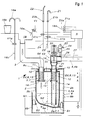
- the main parts of the temporary collecting device 1 or excrement at a treatment place, here a dental treatment center, are a Collection container 2 and / or an odor trap 2.1, one Feed line 3, a discharge line 4 and a balance 5 for the collection container 2 and / or the odor trap 2.1 and an electrical control device S with a Evaluation circuit for the measurement results of the scale 5.
- the Evaluation circuit is in a control unit of the Treatment place integrated, which for reasons of simplification is not shown.
- the discharge line 4 is with a Connected suction device, which will be described.
- the pipe socket 11, 12 penetrate the ceiling wall 2c of the collecting container 2 in guide holes 13 in the Ceiling wall 2c.
- Spring abutment 14 provided for two identical springs 15, preferably for the pipe stub 11, 12 surrounding compression coil springs, on the upper ends of the collecting chamber 2 with its ceiling wall 2c rests. The arrangement can be made in this way be that the springs 15, the collection chamber 2 with a certain Press the preload against the ceiling wall 6c.
- a major advantage of the configuration according to the invention is that the existing sensor, namely the respective level N1, N2 determining switch, here the Switch S1, and at least one more too descriptive switch outside the dirt area are arranged and, on the one hand, not susceptible to interference and on the other hand in the clean room area outside the Collecting container 2 are arranged where they are not only are easy to use, but also easier can be installed and removed.
- the system according to the invention therefore works very reliably.
- the valve V2 By arranging the shut-off valve V2 at a high level, here outside the collection container 2 and in particular about the latter and preferably at the upstream end section one laid with a slight slope Exhaust pipe section, the valve V2 is outside the collection area of sedimenting dirty liquid. It is therefore only dynamic during the suction process Dirt particles loaded. There is no risk of Sedimentation. The valve V2 is located thus in an optimal working position.
- the filling level in the collecting container 2 is reached, so that the switch S1 is operated and simultaneously or successively opened the shut-off valve V2 and the Suction device can be switched on.
- the Collection container 2 suctioned off and emptied. Because of that weight reduction takes place the collecting container 2 pushed up by the spring force of the spring 15. Of the Switch S1 is then no longer actuated, causing the Suction device switched off and the shut-off valve V2 be closed automatically.
- the suction or Emptying amount can be set by a timer or the like are predetermined so that the suction device after their activation a predetermined time runs on and then automatically turns off, causing a certain Filling quantity is emptied.
- a cleaning process can be carried out at certain intervals e.g. daily or weekly or before longer ones Downtimes, e.g. at the end of the practice or before the weekend, done manually or automatically.
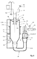
- FIG. 5 shows a safety device that then comes into operation if a fault, e.g. a Faulty switch S1, no drainage occurred.
- a fault e.g. a Faulty switch S1
- the collecting container 2 sinks due to its increased weight over the switch position for the Switch S1 down.
- a sensor e.g. a second switch S2, the inlet, here the water emitting lines 16a, 16c, to the bowl 16 and stopped the suction device switched on.
- the water or excrement in the Collection container 2 can thus up to the inside of the deeper than the cusp 16 arranged check valve V2 or climb to the discharge line section 27 and through the Shut off the V2 shut-off valve without causing a Water leakage in the area of the collecting tank 2 or in the Area of the bowl 16 comes. It is under the Invention thus possible without such a flushing process Suction of the suction device manually or automatically (program-controlled) in the way of working.
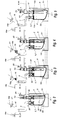
- a corresponding increase in weight of the container 2 in the lateral and preferably upper area of the collecting container 2 arranged switches S1 during a lateral tilting movement of the collecting container 2 released and thereby switched. It is advantageous to switch S1 in the upper area of the Arrange container 2, which makes larger movements of the Collection container are specified.
- the plunger 41 By repeatedly pressing and releasing the plunger 41 can also be a previously described intermittent effect of the cleaning suction can be achieved in which the secondary air 32 is alternately admitted and again is blocked.
- the Sealing plug 45 on the plunger 41 opposite Side wall 6b arranged and attached.
- the previously described impairment of excrement removal in the discharge line 4 results in particular in one flat laid discharge line 4, which may be can extend over several meters. Especially in this Drainage area tend to excrement themselves in it to stop transporting water.
- One finds Sedimentation of the heavy parts of the medium to be pumped takes place. Specifically, this means that heavy parts such as metal and Deposit amalagam sanding and with the pipe wall crust. This makes the line wall rough, which too contributes to impairment of the removal.
- the above described deposit processes occur in particular longer downtimes, such as overnight or on Weekend.
- the Piston cylinder 61 can be located under the discharge line 4 be arranged, the piston rod 59 the wall of the Drainage line 4 penetrated sealed from below.
- the Valve seat is labeled 61a.
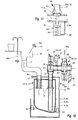
- the above-described supply device 55 for transport air is particularly suitable for multi-station wet suction 12, in which a plurality of dental treatment places A, B and C each with a treatment chair and with a common suction device 65 are connected in the next a suction machine 66, preferably an amalgam separator 67 and a separator 68 are integrated.
- the Treatment places A, B and C are each with their Exhaust line sections 4b preferably in series with connected to a common discharge line section 4c, which is mainly horizontal or with a slight gradient extends, e.g. laid in the floor or in a building ceiling, is and thus with respect to the above Sedimentation problem is particularly at risk.
- the Check valves V3 can be arranged according to FIG.
- the following describes a procedure for cleaning and / or reducing or avoiding sedimentation in the supply line 3, the collecting container 2 and / or the Odor trap 2.1 and the exhaust line 4 comprehensive Drain pipe is used.
- the Drain pipe at least over part of its length, preferably over its entire length, namely at present dental medical treatment place A, B, C of the bowl 16 starting, rinsed with water.
- the breeding ground for microorganisms impaired or eliminates the growths and incrustations in the drain line form, leading to malfunctions such as blockages in the pipe and hose system as well as defects on valves, on one Can lead separator and / or an amalgam separator. This also causes unpleasant smells and infections reduced or avoided for the practice staff that the necessary maintenance work.
Landscapes
- Health & Medical Sciences (AREA)
- Dentistry (AREA)
- Epidemiology (AREA)
- Life Sciences & Earth Sciences (AREA)
- Animal Behavior & Ethology (AREA)
- General Health & Medical Sciences (AREA)
- Public Health (AREA)
- Veterinary Medicine (AREA)
- Dental Tools And Instruments Or Auxiliary Dental Instruments (AREA)
- Sampling And Sample Adjustment (AREA)
- Orthopedics, Nursing, And Contraception (AREA)
Applications Claiming Priority (2)
| Application Number | Priority Date | Filing Date | Title |
|---|---|---|---|
| DE19700118 | 1997-01-03 | ||
| DE19700118A DE19700118A1 (de) | 1997-01-03 | 1997-01-03 | Verfahren und Vorrichtung zum Entleeren eines Sammelbehälters für fließfähige Exkremente an einem medizinischen, insbesondere zahnmedizinischen Behandlungsplatz |
Publications (3)
| Publication Number | Publication Date |
|---|---|
| EP0852129A2 true EP0852129A2 (fr) | 1998-07-08 |
| EP0852129A3 EP0852129A3 (fr) | 2002-06-19 |
| EP0852129B1 EP0852129B1 (fr) | 2005-12-07 |
Family
ID=7816815
Family Applications (1)
| Application Number | Title | Priority Date | Filing Date |
|---|---|---|---|
| EP98100019A Expired - Lifetime EP0852129B1 (fr) | 1997-01-03 | 1998-01-02 | Procédé et dispositif pour vider un collecteur de déchets fluides compris dans un poste de traitement médical, en particulier dentaire |
Country Status (3)
| Country | Link |
|---|---|
| EP (1) | EP0852129B1 (fr) |
| AT (1) | ATE311829T1 (fr) |
| DE (2) | DE19700118A1 (fr) |
Cited By (3)
| Publication number | Priority date | Publication date | Assignee | Title |
|---|---|---|---|---|
| EP1020163A1 (fr) * | 1999-01-18 | 2000-07-19 | Cattani S.P.A. | Dispositif séparateur et évacuateur de déchets liquides pour un appareil dentaire d'aspiration |
| WO2005104987A1 (fr) * | 2004-05-02 | 2005-11-10 | Dürr Dental GmbH & Co. KG | Sonde de niveau de sediment |
| WO2007096368A1 (fr) | 2006-02-23 | 2007-08-30 | Sirona Dental Systems Gmbh | Unité de rinçage dentaire |
Citations (1)
| Publication number | Priority date | Publication date | Assignee | Title |
|---|---|---|---|---|
| EP0406635A2 (fr) | 1989-06-24 | 1991-01-09 | Dürr-Dental GmbH & Co. KG | Installation de crachoir dentaire |
Family Cites Families (2)
| Publication number | Priority date | Publication date | Assignee | Title |
|---|---|---|---|---|
| GB1106858A (en) * | 1965-11-01 | 1968-03-20 | Electrolux Ab | Aspirator apparatus for dental purposes |
| DE9117064U1 (de) * | 1991-02-14 | 1995-07-06 | Sirona Dental Systems GmbH, 64625 Bensheim | Ventilanordnung in einer zahnärztlichen Absauganlage |
-
1997
- 1997-01-03 DE DE19700118A patent/DE19700118A1/de not_active Withdrawn
-
1998
- 1998-01-02 EP EP98100019A patent/EP0852129B1/fr not_active Expired - Lifetime
- 1998-01-02 DE DE59813248T patent/DE59813248D1/de not_active Expired - Lifetime
- 1998-01-02 AT AT98100019T patent/ATE311829T1/de active
Patent Citations (1)
| Publication number | Priority date | Publication date | Assignee | Title |
|---|---|---|---|---|
| EP0406635A2 (fr) | 1989-06-24 | 1991-01-09 | Dürr-Dental GmbH & Co. KG | Installation de crachoir dentaire |
Cited By (3)
| Publication number | Priority date | Publication date | Assignee | Title |
|---|---|---|---|---|
| EP1020163A1 (fr) * | 1999-01-18 | 2000-07-19 | Cattani S.P.A. | Dispositif séparateur et évacuateur de déchets liquides pour un appareil dentaire d'aspiration |
| WO2005104987A1 (fr) * | 2004-05-02 | 2005-11-10 | Dürr Dental GmbH & Co. KG | Sonde de niveau de sediment |
| WO2007096368A1 (fr) | 2006-02-23 | 2007-08-30 | Sirona Dental Systems Gmbh | Unité de rinçage dentaire |
Also Published As
| Publication number | Publication date |
|---|---|
| DE59813248D1 (de) | 2006-01-12 |
| ATE311829T1 (de) | 2005-12-15 |
| EP0852129A3 (fr) | 2002-06-19 |
| DE19700118A1 (de) | 1998-07-09 |
| EP0852129B1 (fr) | 2005-12-07 |
Similar Documents
| Publication | Publication Date | Title |
|---|---|---|
| EP0320696B2 (fr) | Baignoire de bain à remous comprenant un système de prérinçage automatique | |
| DE2929804C2 (de) | Zahnärztliche Absaugeinrichtung | |
| DE4117475C2 (de) | Milchflussmesser | |
| WO1990001909A1 (fr) | Procede et dispositif pour empecher les defaillances d'un systeme d'aspiration dentaire | |
| EP1988846B1 (fr) | Unité de rinçage dentaire | |
| EP0332090B1 (fr) | Appareil pour aspirer et évacuer un liquide contenant des matières nocives notamment de l'eau sale | |
| DE60124980T2 (de) | Vorrichtung zum Spülen eines Toilettenbeckens oder dergleichen | |
| EP0852129B1 (fr) | Procédé et dispositif pour vider un collecteur de déchets fluides compris dans un poste de traitement médical, en particulier dentaire | |
| EP0852130B1 (fr) | Système d'évacuation de déchets fluides d'un poste de traitement médical ou dentaire | |
| DE102005018879A1 (de) | Geschirrspüler | |
| DE2232622C3 (de) | Klosettspülvorrichtung mit Umlauf der Reinigungsflüssigkeit | |
| DE3916743C2 (de) | Druckwasser-Versorgungseinrichtung | |
| EP0406635B1 (fr) | Installation de crachoir dentaire | |
| EP1614816B1 (fr) | Dispositif de vidange et de trop-plein pour appareils sanitaires | |
| DE2841235A1 (de) | Wc-einrichtung | |
| DE204397C (fr) | ||
| DE117283C (fr) | ||
| CH711100A2 (de) | Vorrichtung zur Reinigung einer Toilette oder eines Pissoirs mit einem Wasserspülkasten. | |
| DE1609217C3 (de) | Zulaufeinrichtung zu Badewannen | |
| DE726490C (de) | Selbsttaetig arbeitende Vorrichtung zur Reinigung der Siebanordnung einer Pumpensaugleitung | |
| DE154944C (fr) | ||
| DE144085C (fr) | ||
| DE29710584U1 (de) | Absperrvorrichtung von Hand fernverstellbar | |
| DE1930426U (de) | Kondenstopf. | |
| DE1609217B2 (de) | Zulaufeinrichtung zu badewannen |
Legal Events
| Date | Code | Title | Description |
|---|---|---|---|
| PUAI | Public reference made under article 153(3) epc to a published international application that has entered the european phase |
Free format text: ORIGINAL CODE: 0009012 |
|
| AK | Designated contracting states |
Kind code of ref document: A2 Designated state(s): AT BE CH DE DK ES FI FR GB GR IE IT LI LU MC NL PT SE |
|
| AX | Request for extension of the european patent |
Free format text: AL;LT;LV;MK;RO;SI |
|
| PUAL | Search report despatched |
Free format text: ORIGINAL CODE: 0009013 |
|
| AK | Designated contracting states |
Kind code of ref document: A3 Designated state(s): AT BE CH DE DK ES FI FR GB GR IE IT LI LU MC NL PT SE |
|
| AX | Request for extension of the european patent |
Free format text: AL;LT;LV;MK;RO;SI |
|
| 17P | Request for examination filed |
Effective date: 20021217 |
|
| AKX | Designation fees paid |
Designated state(s): AT DE IT |
|
| RAP1 | Party data changed (applicant data changed or rights of an application transferred) |
Owner name: KALTENBACH & VOIGT GMBH & CO. KG |
|
| GRAP | Despatch of communication of intention to grant a patent |
Free format text: ORIGINAL CODE: EPIDOSNIGR1 |
|
| GRAS | Grant fee paid |
Free format text: ORIGINAL CODE: EPIDOSNIGR3 |
|
| GRAA | (expected) grant |
Free format text: ORIGINAL CODE: 0009210 |
|
| RAP1 | Party data changed (applicant data changed or rights of an application transferred) |
Owner name: KALTENBACH & VOIGT GMBH |
|
| AK | Designated contracting states |
Kind code of ref document: B1 Designated state(s): AT DE IT |
|
| REF | Corresponds to: |
Ref document number: 59813248 Country of ref document: DE Date of ref document: 20060112 Kind code of ref document: P |
|
| PLBE | No opposition filed within time limit |
Free format text: ORIGINAL CODE: 0009261 |
|
| STAA | Information on the status of an ep patent application or granted ep patent |
Free format text: STATUS: NO OPPOSITION FILED WITHIN TIME LIMIT |
|
| 26N | No opposition filed |
Effective date: 20060908 |
|
| PGFP | Annual fee paid to national office [announced via postgrant information from national office to epo] |
Ref country code: DE Payment date: 20160201 Year of fee payment: 19 Ref country code: IT Payment date: 20160129 Year of fee payment: 19 |
|
| PGFP | Annual fee paid to national office [announced via postgrant information from national office to epo] |
Ref country code: AT Payment date: 20160125 Year of fee payment: 19 |
|
| REG | Reference to a national code |
Ref country code: DE Ref legal event code: R119 Ref document number: 59813248 Country of ref document: DE |
|
| REG | Reference to a national code |
Ref country code: AT Ref legal event code: MM01 Ref document number: 311829 Country of ref document: AT Kind code of ref document: T Effective date: 20170102 |
|
| PG25 | Lapsed in a contracting state [announced via postgrant information from national office to epo] |
Ref country code: AT Free format text: LAPSE BECAUSE OF NON-PAYMENT OF DUE FEES Effective date: 20170102 |
|
| PG25 | Lapsed in a contracting state [announced via postgrant information from national office to epo] |
Ref country code: DE Free format text: LAPSE BECAUSE OF NON-PAYMENT OF DUE FEES Effective date: 20170801 |
|
| PG25 | Lapsed in a contracting state [announced via postgrant information from national office to epo] |
Ref country code: IT Free format text: LAPSE BECAUSE OF NON-PAYMENT OF DUE FEES Effective date: 20170102 |