EP0852150B1 - Blut-Gas-Trennvorrichtung - Google Patents
Blut-Gas-Trennvorrichtung Download PDFInfo
- Publication number
- EP0852150B1 EP0852150B1 EP97119489A EP97119489A EP0852150B1 EP 0852150 B1 EP0852150 B1 EP 0852150B1 EP 97119489 A EP97119489 A EP 97119489A EP 97119489 A EP97119489 A EP 97119489A EP 0852150 B1 EP0852150 B1 EP 0852150B1
- Authority
- EP
- European Patent Office
- Prior art keywords
- blood
- suction
- gas
- chamber
- inlet
- Prior art date
- Legal status (The legal status is an assumption and is not a legal conclusion. Google has not performed a legal analysis and makes no representation as to the accuracy of the status listed.)
- Expired - Lifetime
Links
- 239000008280 blood Substances 0.000 title claims abstract description 178
- 210000004369 blood Anatomy 0.000 title claims abstract description 178
- 230000017531 blood circulation Effects 0.000 claims abstract description 19
- 239000006260 foam Substances 0.000 claims description 3
- 239000007789 gas Substances 0.000 description 46
- 238000005119 centrifugation Methods 0.000 description 9
- 208000027418 Wounds and injury Diseases 0.000 description 5
- 238000007872 degassing Methods 0.000 description 4
- 238000000926 separation method Methods 0.000 description 4
- 230000001174 ascending effect Effects 0.000 description 2
- 238000001914 filtration Methods 0.000 description 2
- 239000000463 material Substances 0.000 description 2
- 206010005372 Blood blister Diseases 0.000 description 1
- 241001631457 Cannula Species 0.000 description 1
- 238000010521 absorption reaction Methods 0.000 description 1
- 230000001133 acceleration Effects 0.000 description 1
- 230000036765 blood level Effects 0.000 description 1
- 239000000356 contaminant Substances 0.000 description 1
- 238000000502 dialysis Methods 0.000 description 1
- 230000000694 effects Effects 0.000 description 1
- 239000012530 fluid Substances 0.000 description 1
- 239000011521 glass Substances 0.000 description 1
- 239000012535 impurity Substances 0.000 description 1
- 239000002184 metal Substances 0.000 description 1
- 239000000203 mixture Substances 0.000 description 1
- 230000002572 peristaltic effect Effects 0.000 description 1
- 230000000630 rising effect Effects 0.000 description 1
- 238000013022 venting Methods 0.000 description 1
- 238000005406 washing Methods 0.000 description 1
Images


Classifications
-
- A—HUMAN NECESSITIES
- A61—MEDICAL OR VETERINARY SCIENCE; HYGIENE
- A61M—DEVICES FOR INTRODUCING MEDIA INTO, OR ONTO, THE BODY; DEVICES FOR TRANSDUCING BODY MEDIA OR FOR TAKING MEDIA FROM THE BODY; DEVICES FOR PRODUCING OR ENDING SLEEP OR STUPOR
- A61M1/00—Suction or pumping devices for medical purposes; Devices for carrying-off, for treatment of, or for carrying-over, body-liquids; Drainage systems
- A61M1/36—Other treatment of blood in a by-pass of the natural circulatory system, e.g. temperature adaptation, irradiation ; Extra-corporeal blood circuits
- A61M1/3621—Extra-corporeal blood circuits
- A61M1/3627—Degassing devices; Buffer reservoirs; Drip chambers; Blood filters
-
- A—HUMAN NECESSITIES
- A61—MEDICAL OR VETERINARY SCIENCE; HYGIENE
- A61M—DEVICES FOR INTRODUCING MEDIA INTO, OR ONTO, THE BODY; DEVICES FOR TRANSDUCING BODY MEDIA OR FOR TAKING MEDIA FROM THE BODY; DEVICES FOR PRODUCING OR ENDING SLEEP OR STUPOR
- A61M1/00—Suction or pumping devices for medical purposes; Devices for carrying-off, for treatment of, or for carrying-over, body-liquids; Drainage systems
- A61M1/71—Suction drainage systems
- A61M1/76—Handpieces
-
- B—PERFORMING OPERATIONS; TRANSPORTING
- B01—PHYSICAL OR CHEMICAL PROCESSES OR APPARATUS IN GENERAL
- B01D—SEPARATION
- B01D19/00—Degasification of liquids
- B01D19/0042—Degasification of liquids modifying the liquid flow
- B01D19/0052—Degasification of liquids modifying the liquid flow in rotating vessels, vessels containing movable parts or in which centrifugal movement is caused
- B01D19/0057—Degasification of liquids modifying the liquid flow in rotating vessels, vessels containing movable parts or in which centrifugal movement is caused the centrifugal movement being caused by a vortex, e.g. using a cyclone, or by a tangential inlet
-
- B—PERFORMING OPERATIONS; TRANSPORTING
- B04—CENTRIFUGAL APPARATUS OR MACHINES FOR CARRYING-OUT PHYSICAL OR CHEMICAL PROCESSES
- B04C—APPARATUS USING FREE VORTEX FLOW, e.g. CYCLONES
- B04C5/00—Apparatus in which the axial direction of the vortex is reversed
- B04C5/02—Construction of inlets by which the vortex flow is generated, e.g. tangential admission, the fluid flow being forced to follow a downward path by spirally wound bulkheads, or with slightly downwardly-directed tangential admission
- B04C5/04—Tangential inlets
Definitions
- the invention relates to a device for separating gas from blood according to the Preamble of claim 1.
- a device of this type for separating gas from blood is known from DE 43 29 385 A1 known. It has a cylindrical centrifugation chamber. At the center of your top A blood inlet distributor with several guide vanes is arranged in the area, which divides a blood stream onto the guide vanes. The individual blood flows are approximately tangential to the cylindrical wall of the inlet manifold Centrifugation chamber driven. Above this blood inlet area is in the Centrifugation chamber an air cushion, from which rising from the blood Air bubbles can be discharged through a vent hole. In the bottom of the Centrifugation chamber is a blood outlet opening.
- US-A-4 710 299 shows a general purpose cyclone separator for Separate dense components of a fluid mixture from less dense ones Components of it.
- Your centrifugation chamber has successive conical ones and cylindrical sections.
- An inlet duct which is essentially tangential and at the same time opens diagonally from top to bottom into the centrifuging chamber a narrowing cross section in the direction of flow to produce a Flow acceleration.
- the denser components are replaced by a Outlet opening in the chamber bottom, and the less dense components will through an outlet opening in the chamber ceiling each axially from the centrifuging chamber led out.
- the quality of blood can be affected, among other things by: the amount and duration of air or other gases in the blood; by suction or pressure forces the blood; by frictional forces of the blood in Flow paths; Redirections of blood flow and Turbulence in the blood.
- the vacuum for sucking the blood is generated by a suction pump, usually a roller pump.
- the suction pump not only draws blood, but often also air at the patient's blood suction point.
- the extracted air is relatively high compared to the extracted blood, for example 5 parts of air to one part of blood (parts by volume).
- the blood suction rate is relatively low, for example 100 to 600 milliliters per minute, and fluctuates widely.
- the suction flow rate of the blood is also relatively low and fluctuates widely.
- the air bubbles in the blood are common relatively large. Their size ranges from Micrometer to millimeter range.
- the present invention relates to this Field of application, namely the degassing of blood, while being sucked off by a patient.
- a blood suction device which consists of a cylindrical housing in which there is microporous Filter material for filtering out air bubbles and other impurities from one of a patient sucked blood flow, a blood suction cannula at a front end of the case and out of a Blood suction line at the rear end of the housing consists.
- GB-A-2 063 108 shows one Blood degassing device for removing gas bubbles, which can be so small that they are in the micro range are, for example, a diameter of only 40 Have micron.
- the blood suction device consists of a vertical cylindrical cyclone chamber, a tangential inlet at the top of the chamber, one opposite to the cyclone rotation tangential arranged blood outlet at the lower end of the chamber Vent pipe, which is in the cyclone axis of rotation from top to bottom to below the blood inlet in the cyclone chamber protrudes, a second Venting device in the form of a radial bore in an upper extension of the cyclone chamber above the Blood inlet, and a second tube, which itself along the cyclone axis of rotation through the entire Cyclone chamber and through part of the former Pipe extends and should serve that at his Outside surface air bubbles collect and face up can rise.
- DE-A-43 29 385 describes that it one compared to the aforementioned GB-A-2 063 108 further developed air separator, in which Blood inlet and blood outlet on each other applied ends of a cylindrical swirl chamber are arranged axially to each other.
- the blood intake is formed by a vane body and in front of the Blood outlet is a filter candle.
- Ascending Blood blisters get into one above the Guide vane body located section of the Vortex chamber where an air cushion is formed which is vented through a hole.
- DE-C-36 41 644 shows a blood flow chamber with a blood inlet halfway up the chamber and one into the flow chamber immersed blood outlet channel. Contained in the blood Air bubbles can only be lifted by the buoyancy Archimedes climb up.
- DE-C-36 24,363 and US-A-5,451,321 devices microporous filter material for filtering gas bubbles or other blood contaminants from a blood stream.
- the object of the invention is to be achieved to design a device so that even with small and fluctuating amounts of blood flow a weak suction or negative pressure is sufficient to do that Blood through a non-rotating centrifuge chamber or suction cyclone chamber that good and quick Separation of blood and gas mixed with it, especially air.
- the invention has the following advantages in particular: Invention is useful for eliminating glass bubbles Size of the centrifugal forces of a cyclone flow Gas suction suction effect from above on the rotating blood, and Archimedes' buoyancy at the same time and support each other, so that already at a weak suction of a suction pump a gentle and at the same time effective separation of the gas phase from the Blood phase takes place.
- the non-rotating Centrifugation chamber or cyclone chamber has the shape of a narrower from the blood inlet to the blood outlet expectant funnel, so that the centrifugal The kinetic energy of the cyclone flow from the blood inlet to is better maintained at the blood outlet than at a non-funnel-shaped, cylindrical chamber.
- a better separation of blood and gas from the blood-gas suction flow according to a special thought the Invention by rotating a gas space Blood flow reached in which gas bubbles and blood-gas foam have enough time and space to get into one Air fraction and a blood fraction to decay before that Gas at a distance above the rotating blood stream is sucked off by a gas suction device.
- the Invention is preferably used for the first Use case in a patient's blood suction flow applied.
- the invention can also according to the third Use case for the effective separation of gas from blood applied separately and independently of a patient by taking blood from a blood container through the Centrifugation chamber or cyclone chamber is sucked.
- the Device can be placed close to a patient become; it is very light in weight; she can as portable one-hand device can be trained; she can inexpensive using standard cannulas getting produced; their handling is simple and for the operator is not tiring.
- a blood suction device for Aspirating blood from a patient, especially from a patient's wound site is a one-hand device and contains a one-part or multi-part, gun-shaped device body 2 made of metal or Plastic, which essentially consists of a handle 4 and a barrel or shaft 6.
- a non-rotating centrifugation chamber hereinafter Cyclone chamber 8 called, to generate one with constant direction of rotation rotating like a cyclone Blood flow around an upright, vertical or near vertical axis of rotation 10 formed.
- the cyclone chamber 8 has a funnel-like narrowing from top to bottom becoming shape so that a sucked through it Blood flow through the entire cyclone chamber Maintained kinetic energy without that strong suction in the cyclone chamber is required.
- a blood inlet suction channel 12 in the shaft 6 opens approximately at a blood inlet opening 13 tangential, and at an angle ⁇ of 90 ° or preferably less than 90 ° to the vertical Rotation axis 10 obliquely from top to bottom, in the funnel-shaped upper section of the funnel-shaped Cyclone chamber 8.
- a blood outlet suction channel 14 extends from a blood outlet opening 15 on the narrow lower End of the cyclone chamber 8 under one, down open, angle ⁇ between 0 ° and 90 °, preferably approximately 30 ° to the axis of rotation 10 through the handle 4 to one attached to its lower end Blood suction tube 16.
- the blood stream rotates without Reverse flows, only in a single vortex direction of rotation.
- the cyclone chamber 8 is arranged above it closed gas space 18 from about 5mm to 15mm height extended, which one over the Cyclone chamber 8 laterally protruding gas space section 20 has.
- the gas space 18 serves as a storage chamber temporary absorption of gas bubbles and blood foam, so that they have time and space to decay in air and blood to have. This will reduce the amount of blood that comes with the gas, separated from the rotating blood stream is suctioned off.
- the gas space 18 also serves temporary admission from if necessary from time to time the cyclone chamber 8 ascending blood.
- the cross section of the gas space 18 is transverse to the axis of rotation 10 at least twice the cross section of a Gas outlet opening 23.
- a gas outlet suction channel 22 Through the handle 4 extends parallel to Blood outlet suction channel 14, a gas outlet suction channel 22, the via the gas outlet opening 23 in the bottom of the side protruding gas space section 20 with the gas space 18th connected is.
- the gas outlet opening 23 is essential arranged higher, e.g. 2mm - 10mm higher than that Blood inlet opening 13.
- a gas suction hose 24 At the lower end of the handle 4 is a gas suction hose 24 to the gas outlet suction channel 22 connected.
- the gas suction hose 24 and the Blood suction hose 16 are separately connected to a suction pump 28 connected, preferably to a peristaltic table Roller pump, which draws the blood and the extracted air in a separate way Blood reservoir 30 promotes.
- the suction pump creates 28 via the blood outlet suction channel 14 and the gas outlet suction channel 22 through the gas space 18 and the cyclone chamber 8 through a suction vacuum in the blood inlet suction channel 12, so that through the blood inlet suction channel 12th Blood is sucked into the cyclone chamber 8.
- the gas space 18 is closed by a cover 34.
- a blood suction cannula 36 is detachably inserted.
- the blood suction cannula 36 also a one-piece part with the Form device body 2.
- the front end portion 38 of the Blood suction cannula 36 is open at the bottom Angle ⁇ angled downwards, for example, from 105 ° and provided with through openings 39 to from a To be able to draw blood from a patient's wound site, when an operator has the device body 2 on Holds handle 4 in a comfortable hand position.
- the angle y of the blood suction cannula 36 are in the range between 90 ° and 180 °.
- the Angle ⁇ and ⁇ are coordinated so that the Device for blood suction conveniently on the handle can be worn while the gas outlet opening 23rd always remains higher than the blood inlet opening 13. Therefore the gas outlet opening 23 is preferred on that facing away from the blood inlet opening 13 Chamber side arranged.
- the downwardly open angle ⁇ between the blood outlet suction channel 14 and the gas outlet suction channel 22 on the one hand and the blood inlet suction channel 12 on the other hand depending on the angles ⁇ and ⁇ between approximately 90 ° and 180 °, preferably according to that shown preferred embodiment at 135 °.
- the Gas outlet suction channel 22 and its gas suction hose 24 the same or a different internal cross-section as or than the blood suction channel 14 and its blood suction tube 16, so that blood and air separate from each other same suction pump 28 can be sucked off, too then when the blood and air are different Have flow volume.
- the invention in the embodiment shown in FIG.
- the invention is a commercially available blood suction cannula 136 used with a handle part 140.
- the downstream rear end portion 137 of this Blood suction cannula 136 forms directly or through Connector 150 the blood inlet suction channel 12 with the Blood inlet opening 13 in the cyclone chamber 8.
- the others in FIG. 4 details shown are constructive and at least functionally identical to the details of FIGS. 1 to 3 and are provided with the same reference numbers.
- the Blood suction cannula 236 has at its downstream, rear end one vertically from top to bottom in that Housing 252 extending pipe piece 256, which the blood inlet suction channel 12 and, at his downstream end, the blood inlet opening 13 forms.
- the gas space 18 is closed by a closure 258 closed at the upper end of the housing 252. It is a suction pump 228.1 for the blood and a suction pump 228.2 intended for the gas, however, both can pass through a single pump 28 corresponding to FIGS. 1 to 4 be replaced.
- the blood outlet suction channels are aligned 14 with the vertical axis of rotation 10 as Cyclone chamber 8 acting centrifugation chamber
Landscapes
- Health & Medical Sciences (AREA)
- Heart & Thoracic Surgery (AREA)
- Vascular Medicine (AREA)
- Animal Behavior & Ethology (AREA)
- Public Health (AREA)
- Engineering & Computer Science (AREA)
- Anesthesiology (AREA)
- Biomedical Technology (AREA)
- Hematology (AREA)
- Life Sciences & Earth Sciences (AREA)
- Veterinary Medicine (AREA)
- General Health & Medical Sciences (AREA)
- Fluid Mechanics (AREA)
- Physics & Mathematics (AREA)
- Chemical & Material Sciences (AREA)
- Chemical Kinetics & Catalysis (AREA)
- Cardiology (AREA)
- External Artificial Organs (AREA)
- Medicines Containing Material From Animals Or Micro-Organisms (AREA)
- Centrifugal Separators (AREA)
Description
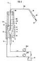
- Fig. 1
- eine Seitenansicht, teilweise längs der Ebene I-I von Fig. 3 geschnitten dargestellt, einer Blutabsaugvorrichtung gemäß der Erfindung im Maßstab 1:1,
- Fig. 2
- eine schematische Längsschnitt-Ansicht längs der Ebene II-II von Fig. 1,
- Fig. 3
- eine Draufsicht von oben auf die Blutabsaugvorrichtung von Fig. 1,
- Fig. 4
- eine Seitenansicht, teilweise geschnitten, einer weiteren Ausführungsform nach der Erfindung,
- Fig. 5
- eine Seitenansicht, teilweise geschnitten, einer nochmals weiteren Ausführungsform der Erfindung.
Claims (8)
- Vorrichtung zum Trennen von Gas aus Blut, enthaltend1.1 eine nicht-rotierende Zentrifugierkammer (8) zum Erzeugen eines mit gleichbleibender Drehrichtung zyklonartig um eine durch die Zentrifugierkammer (8) definierte, aufrechte, vertikale oder nahezu vertikale Rotationsachse (10) rotierenden Blutstromes;1.2 einen Bluteinlaß (12, 13) im oberen Bereich und eine Blutauslaßöffnung (15) im unteren Bereich der Zentrifugierkammer (8), um einen Blutstrom von dem Sog oder dem Unterdruck einer an die Blutauslassöffnung (15) anschließbaren Saugvorrichtung (28) von einer Blutquelle über den Bluteinlaß (12, 13) durch die Zentrifugierkammer (8), in welcher er um die Rotatiosachse rotiert, ohne Umkehrung der Blutstrom-Rotationsrichtung durch die Blutauslaßöffnung (15) zu saugen;1.3 wobei die Strömungsrichtung des Bluteinlasses (12, 13) im wesentlichen tangential zur Rotationsachse (10) des Blutstromes in die Zentrifugierkammer gerichtet ist;1.4 ein mit Höhenabstand höher als der Bluteinlass (12, 13) angeordneter Gasausläß (23);
dadurch gekennzeichnet,1.5 dass der Bluteinlaß ein Bluteinlasskanal (12) mit einer Bluteinlassöffnung (13) ist, der nicht nur tangential, sondern auch schräg von oben nach unten in die Zentrifugierkammer (8) gerichtet ist, unter einem nach oben öffnenden Winkel (β) zur Rotationsachse (10) von weniger als 90°;1.6 dass die Zentrifugierkammer (8) eine von der Bluteinlaßöffnung (13) am oberen Kammerende bis zur Blutauslassöffnung (15) am unteren Kammerende trichterartig enger werdende Form zur Reduzierung des Rotations-Energieverlustes des Saug-Blutstromes aufweist;1.7 dass der Gasauslaß (23) mit einem Saugkanal (22) versehen ist zum Absaugen von Gas von der Oberfläche des in der Zentrifugiertcammer (8) rotierenden Blutstromes durch eine an den Saugkanal (22) anschließbare Saugvorrichtung (28);1.8 dass ein Gasraum (18) vorgesehen ist, der sich von der Zentrifugierkammer (8) oberhalb ihrer Bluteinlaßöffnung (13) mindestens bis zu einer Gasauslaßöffnung (23) des Gasauslasses nach oben erstreckt und einen Querschnitt quer zur Rotationsachse (10) hat, der mindestens zweimal so groß ist wie der Querschnitt der Gasauslaßöffnung (23), und in welchem Gasblasen und Blut-Gas-Schaum Zeit und Raum haben, um in Blutteile und Gasteile zu zerfallen, bevor die Gasteile durch den Gasauslaß (23) von der daran angeschlossenen Saugquelle (28) abgesaugt werden. - Vorrichtung nach Anspruch 1, dadurch gekennzeichnet, dass an den Bluteinlaßkanal (12) eine Blutabsaugkanüle (36; 136; 236) angeschlossen ist oder der Bluteinlaßkanal (12) durch eine solche Blutabsaugkanüle gebildet ist.
- Vorrichtung nach Anspruch 1 oder 2, dadurch gekennzeichnet, dass sie als ein mit einer Hand tragbares Gerät ausgebildet und mit einem Handgriffteil (4; 140; 240) versehen ist.
- Vorrichtung nach Anspruch 3, dadurch gekennzeichnet, dass die Zentrifugierkammer (8) am vorderen oder oberen Ende des Handgriffteils (4) angeordnet ist, welches entgegengesetzt zur Blutströmungsrichtung gerichtet ist.
- Vorrichtung nach Anspruch 3, dadurch gekennzeichnet, dass die Zentrifugierkammer (8) am hinteren oder unteren Ende, bezüglich der Blutstromrichtung stromabwärts des Handgriffteils (140) angeordnet ist.
- Vorrichtung nach Anspruch 3, dadurch gekennzeichnet, dass die Zentrifugierkammer (8) in den Handgriffteil (240) integriert ist.
- Vorrichtung nach einem der Ansprüche 3 bis 6, dadurch gekennzeichnet, dass der Handgriffteit (140) an der Blutabsaugkanüle (136) vorgesehen ist.
- Vorrichtung nach einem der vorhergehenden Ansprüche, dadurch gekennzeichnet, dass die Blutauslaßöffnung (15) eine andere Querschnittsgröße hat als der Gasauslaß (23).
Applications Claiming Priority (2)
| Application Number | Priority Date | Filing Date | Title |
|---|---|---|---|
| DE19650407A DE19650407A1 (de) | 1996-12-05 | 1996-12-05 | Blut-Gas-Trennverfahren und -Trennvorrichtung |
| DE19650407 | 1996-12-05 |
Publications (3)
| Publication Number | Publication Date |
|---|---|
| EP0852150A2 EP0852150A2 (de) | 1998-07-08 |
| EP0852150A3 EP0852150A3 (de) | 1998-10-07 |
| EP0852150B1 true EP0852150B1 (de) | 2003-03-19 |
Family
ID=7813691
Family Applications (1)
| Application Number | Title | Priority Date | Filing Date |
|---|---|---|---|
| EP97119489A Expired - Lifetime EP0852150B1 (de) | 1996-12-05 | 1997-11-07 | Blut-Gas-Trennvorrichtung |
Country Status (5)
| Country | Link |
|---|---|
| US (1) | US6066111A (de) |
| EP (1) | EP0852150B1 (de) |
| AT (1) | ATE234647T1 (de) |
| DE (2) | DE19650407A1 (de) |
| ES (1) | ES2189915T3 (de) |
Families Citing this family (23)
| Publication number | Priority date | Publication date | Assignee | Title |
|---|---|---|---|---|
| US6334234B1 (en) | 1999-01-08 | 2002-01-01 | Fantom Technologies Inc. | Cleaner head for a vacuum cleaner |
| US6141826A (en) | 1999-01-08 | 2000-11-07 | G.B.D. Corp. | Center air feed for cyclonic separator |
| ATE505223T1 (de) | 2002-07-19 | 2011-04-15 | Baxter Int | System für die peritonealdialyse |
| US7488448B2 (en) * | 2004-03-01 | 2009-02-10 | Indian Wells Medical, Inc. | Method and apparatus for removal of gas bubbles from blood |
| US7947112B1 (en) | 2007-07-16 | 2011-05-24 | Rheodyne, Llc | Method for degassing a fluid |
| US7892332B2 (en) * | 2007-10-01 | 2011-02-22 | Baxter International Inc. | Dialysis systems having air traps with internal structures to enhance air removal |
| US7892331B2 (en) | 2007-10-01 | 2011-02-22 | Baxter International Inc. | Dialysis systems having air separation chambers with internal structures to enhance air removal |
| US8444587B2 (en) | 2007-10-01 | 2013-05-21 | Baxter International Inc. | Fluid and air handling in blood and dialysis circuits |
| US7871462B2 (en) * | 2007-10-01 | 2011-01-18 | Baxter International Inc. | Dialysis systems having air separation chambers with internal structures to enhance air removal |
| US8123947B2 (en) * | 2007-10-22 | 2012-02-28 | Baxter International Inc. | Priming and air removal systems and methods for dialysis |
| US8114276B2 (en) | 2007-10-24 | 2012-02-14 | Baxter International Inc. | Personal hemodialysis system |
| CN101939110B (zh) | 2007-12-19 | 2015-01-21 | Gbd公司 | 旋风分离器组件的结构以及具有所述旋风分离器组件的表面清洁装置 |
| US8057679B2 (en) | 2008-07-09 | 2011-11-15 | Baxter International Inc. | Dialysis system having trending and alert generation |
| DE102009024465B4 (de) * | 2009-06-10 | 2015-03-05 | Fresenius Medical Care Deutschland Gmbh | Blutkassette mit Luftabscheider, Blutkreislauf sowie Behandlungsvorrichtung |
| EP2421584B1 (de) | 2009-04-23 | 2016-04-13 | Fresenius Medical Care Deutschland GmbH | Luftabscheider, externe funktionseinrichtung, blutkreislauf sowie behandlungsvorrichtung |
| US8382711B2 (en) | 2010-12-29 | 2013-02-26 | Baxter International Inc. | Intravenous pumping air management systems and methods |
| DE102011084027A1 (de) | 2011-10-05 | 2013-04-11 | Maquet Cardiopulmonary Ag | Schnellkupplungsvorrichtung |
| US9486590B2 (en) | 2014-09-29 | 2016-11-08 | Fenwal, Inc. | Automatic purging of air from a fluid processing system |
| EP3314488B1 (de) | 2015-06-25 | 2024-03-13 | Gambro Lundia AB | Medizinisches vorrichtungssystem und verfahren mit einer verteilten datenbank |
| US10625009B2 (en) | 2016-02-17 | 2020-04-21 | Baxter International Inc. | Airtrap, system and method for removing microbubbles from a fluid stream |
| KR102476516B1 (ko) | 2016-12-21 | 2022-12-09 | 감브로 룬디아 아베 | 외부 도메인을 지원하는 안전한 클러스터 도메인을 구비한 정보 기술 인프라를 포함하는 의료 장치 시스템 |
| DE102018115250B4 (de) * | 2018-06-25 | 2020-04-16 | Georg-August-Universität Göttingen Stiftung Öffentlichen Rechts, Universitätsmedizin | Saugkopf zum schonenden Absaugen thixotroper Flüssigkeiten |
| WO2021098939A1 (de) | 2019-11-18 | 2021-05-27 | Georg-August-Universität Göttingen Stiftung Öffentlichen Rechts, Universitätsmedizin | Saugkopf zum schonenden absaugen thixotroper flüssigkeiten |
Citations (1)
| Publication number | Priority date | Publication date | Assignee | Title |
|---|---|---|---|---|
| US3785380A (en) * | 1972-02-22 | 1974-01-15 | R Brumfield | Filtering blood sucker |
Family Cites Families (83)
| Publication number | Priority date | Publication date | Assignee | Title |
|---|---|---|---|---|
| US2511967A (en) * | 1950-06-20 | Gas and liquto separator | ||
| US2876860A (en) * | 1956-11-13 | 1959-03-10 | Clark & Vicario Corp | De-aerating hydrocyclones |
| US3715863A (en) * | 1971-03-26 | 1973-02-13 | Bennett Pump Inc | Compact pump/air separator apparatus |
| US3994689A (en) * | 1971-09-08 | 1976-11-30 | Dewall Richard A | Metabolic bubble oxygenator |
| US3771290A (en) * | 1971-12-06 | 1973-11-13 | Armstrong Ltd S A | Vortex de-aerator |
| BE792243A (fr) * | 1971-12-23 | 1973-03-30 | Baxter Laboratories Inc | Piege a bulles pour l'enlevement de bulles hors d'un fluide biologique dans des conditions assurant la sterilite |
| US3804686A (en) * | 1972-04-06 | 1974-04-16 | Goodyear Aerospace Corp | Process for making tunnel structure for plated wire |
| US3833013A (en) * | 1972-04-06 | 1974-09-03 | Baxter Laboratories Inc | Self-valving fluid reservoir and bubble trap |
| US3807401A (en) * | 1972-06-21 | 1974-04-30 | Department Of Health Education | Anticoagulating blood suction device |
| US3812655A (en) * | 1973-01-23 | 1974-05-28 | D Bennett | Gas-liquid separator |
| JPS5523083B2 (de) * | 1973-10-10 | 1980-06-20 | ||
| US3965896A (en) * | 1974-06-17 | 1976-06-29 | Swank Roy L | Blood autotransfusion method and apparatus |
| US3955573A (en) * | 1974-10-11 | 1976-05-11 | Sorenson Research Co., Inc. | Anticoagulant delivery device and method |
| US3996027A (en) * | 1974-10-31 | 1976-12-07 | Baxter Laboratories, Inc. | Swirling flow bubble trap |
| US4054522A (en) * | 1975-09-03 | 1977-10-18 | Harry Pinkerton | Apparatus for exposing a fluid to a negative pressure |
| US4061031A (en) * | 1975-11-05 | 1977-12-06 | Lars Grimsrud | Combination of flow meter and bubble trap |
| SE7702333L (sv) * | 1976-03-11 | 1977-09-12 | Augsburg & Nurnberg Ag Maschf | Forfarande och anordning for avskiljande av gasblasor ur strommande vetskor och kylsystem for vetskekylda forbrenningsmotorer |
| DE2611383C2 (de) * | 1976-03-18 | 1985-01-31 | Salvia Regel- Und Medizintechnik Gmbh, 6231 Schwalbach | Verfahren zum Nachweis des Blutübertritts in eine Spülflüssigkeit bei der Hämodialyse und Vorrichtung zur Durchführung des Verfahrens |
| DE2621051A1 (de) * | 1976-05-12 | 1977-12-01 | Volkswagenwerk Ag | Zyklonvorrichtung |
| US4053291A (en) * | 1976-08-18 | 1977-10-11 | The United States Of America As Represented By The Secretary Of The Air Force | Cylindrical deaerator |
| US4093428A (en) * | 1977-04-12 | 1978-06-06 | The United States Of America As Represented By The Secretary Of The Navy | Gas/liquid separator |
| US4102655A (en) * | 1977-05-02 | 1978-07-25 | Cobe Laboratories, Inc. | Bubble trap |
| US4276170A (en) * | 1978-08-16 | 1981-06-30 | Critikon, Inc. | Vented flexible filtration device for use in administering parenteral liquids |
| US4394138A (en) * | 1979-01-19 | 1983-07-19 | Schilling John R | Diverging vortex separator |
| US4282016A (en) * | 1979-02-01 | 1981-08-04 | Technical Development Co. | Gas and failure particle separator system |
| GB2063108A (en) * | 1979-09-28 | 1981-06-03 | Bethune D | Degassing device |
| US4344777A (en) * | 1980-01-07 | 1982-08-17 | Siposs George G | Directed flow bubble trap for arterial blood |
| US4368118A (en) * | 1980-01-07 | 1983-01-11 | Siposs George G | Blood-air separator and filter |
| US4360428A (en) * | 1980-05-01 | 1982-11-23 | Comparetto John E | Inverted vortex, particle separation chamber |
| DE3024099A1 (de) * | 1980-06-27 | 1982-01-21 | Seitz-Werke Gmbh, 6550 Bad Kreuznach | Verfahren und vorrichtung zur rueckgewinnung eines inerten gases |
| US4316271A (en) * | 1981-01-14 | 1982-02-16 | Honeywell Inc. | Purging and expansion mechanism |
| US4345919A (en) * | 1981-01-19 | 1982-08-24 | Texas Medical Products, Inc. | Degasser for biological fluids |
| US4435170A (en) * | 1981-06-15 | 1984-03-06 | Solco Basel Ag | Assembly for receiving and discharging a collection of blood |
| US4433971A (en) * | 1981-06-30 | 1984-02-28 | Minnesota Mining And Manufacturing Company | Integrated cardioplegia delivery system |
| US4388922A (en) * | 1981-07-29 | 1983-06-21 | Becton, Dickinson And Company | Suction canister system for serial collection of fluids |
| JPS5836606A (ja) * | 1981-08-26 | 1983-03-03 | Ishikawajima Harima Heavy Ind Co Ltd | 流体中の気泡集合方法 |
| US4474184A (en) * | 1982-09-27 | 1984-10-02 | Advanced Technology Laboratories, Inc. | Bubble trap for ultrasound scanhead |
| US4475932A (en) * | 1983-01-21 | 1984-10-09 | Amtrol Inc. | Gas-liquid vortex separator-eliminator |
| US4555253A (en) * | 1983-01-21 | 1985-11-26 | Amtrol, Inc. | Gas-liquid vortex separator-eliminator |
| US4547186A (en) * | 1983-03-07 | 1985-10-15 | Bartlett Robert H | Autotransfusion system |
| JPS59228849A (ja) * | 1983-06-10 | 1984-12-22 | テルモ株式会社 | 液体中気泡除去装置 |
| US4710299A (en) * | 1984-01-24 | 1987-12-01 | Noel Carroll | Cyclone separator |
| DE3542555A1 (de) * | 1985-12-02 | 1987-06-04 | Bosch Siemens Hausgeraete | Abscheider fuer in einem gasstrom mitgerissene feststoffpartikel, insb. reif- und/oder eiskristalle |
| US4681606A (en) | 1986-02-26 | 1987-07-21 | Cobe Laboratories, Inc. | Drip chamber |
| DE3624363C2 (de) * | 1986-07-18 | 1995-06-08 | Akzo Gmbh | Vorrichtung zum Abtrennen von Gasblasen aus Infusionsflüssigkeiten oder Flüssigkeiten des menschlichen Körpers |
| FR2610105A1 (fr) * | 1987-01-26 | 1988-07-29 | Elf Aquitaine | Procede et separateur-compteur diphasique pour mesurer, en continu et respectivement, les quantites de gaz et de liquide debitees dans un ecoulement dynamique d'un melange de gaz et de liquide |
| US4900308A (en) * | 1987-05-27 | 1990-02-13 | Level 1 Technologies, Inc. | Gas elimination device |
| JPH01148266A (ja) * | 1987-12-04 | 1989-06-09 | Terumo Corp | 血液フィルター |
| MY103493A (en) * | 1987-11-24 | 1993-06-30 | Conoco Specialty Prod | Cyclone separator |
| US4874359A (en) * | 1987-12-14 | 1989-10-17 | White Frederick R | Power infuser |
| US4806135A (en) * | 1988-03-01 | 1989-02-21 | Siposs George G | Bubble trap for phase-separating gas bubbles from flowing liquids |
| US4976685A (en) * | 1988-06-15 | 1990-12-11 | Block Jr Frank E | Method of blood-gas interface control in surgical gas traps |
| CA2001956A1 (en) * | 1988-12-14 | 1990-06-14 | Ronald J. Leonard | Membrane blood oxygenator |
| US4919826A (en) * | 1988-12-20 | 1990-04-24 | Air Techniques, Incorporated | Process and apparatus for separating solids and liquids from an effluent stream |
| US4997556A (en) * | 1988-12-26 | 1991-03-05 | Mitsubishi Oil Co., Ltd. | Oil filter I |
| US5000766A (en) * | 1989-05-30 | 1991-03-19 | Mitsubishi Oil Co., Ltd. | Suction system gas separator from fluid |
| US4940473A (en) * | 1989-06-16 | 1990-07-10 | Benham Roger A | Cyclone solids separator and de-gasifier |
| GB8921566D0 (en) * | 1989-09-23 | 1989-11-08 | Atomic Energy Authority Uk | Degassing apparatus |
| US5188604A (en) * | 1989-09-29 | 1993-02-23 | Rocky Mountain Research, Inc. | Extra corporeal support system |
| US5126054A (en) * | 1990-05-24 | 1992-06-30 | Pall Corporation | Venting means |
| US5061236A (en) * | 1990-07-16 | 1991-10-29 | Baxter International Inc. | Venous reservoir with improved inlet configuration and integral screen for bubble removal |
| US5171405A (en) * | 1990-08-28 | 1992-12-15 | Kamyr, Inc. | Reactor having a discontinuous conduit means between surfaces of a downwardly extending stationary spiral |
| FR2673382B1 (fr) * | 1991-03-01 | 1994-04-08 | Hospal Industrie | Dispositif pour eliminer les bulles de gaz d'un liquide en circulation. |
| FR2676365B1 (fr) * | 1991-05-13 | 1993-08-20 | Gerard Adhoute | Dispositif d'aspiration pour autotransfusion per-operatoire. |
| US5250093A (en) * | 1992-03-09 | 1993-10-05 | O. I. Corporation | Water management device for gas chromatography sample concentration |
| US5411472A (en) * | 1992-07-30 | 1995-05-02 | Galen Medical, Inc. | Low trauma blood recovery system |
| DE4227695C1 (de) * | 1992-08-21 | 1993-10-07 | Fresenius Ag | Zentrifuge zum Auftrennen von Blut in seine Bestandteile |
| US5429595A (en) * | 1992-11-12 | 1995-07-04 | Wright, Jr.; Fred G. | Arterial safety air diverter |
| US5453196A (en) * | 1993-07-09 | 1995-09-26 | Tuszko; Wlodzimierz J. | Induced long vortex cyclone separation method and apparatus |
| DE4326886C2 (de) * | 1993-08-11 | 1995-08-24 | Herbert Bock | Vorrichtung zum Absaugen und Aufbereiten von Blut aus Operationsfeldern |
| DE4329385C2 (de) * | 1993-09-01 | 1998-09-17 | Fresenius Ag | Vorrichtung zum Abscheiden von Luftblasen aus Flüssigkeiten |
| US5537335A (en) * | 1993-11-01 | 1996-07-16 | University Of Pittsburgh Of The Commonwealth System Of Higher Education | Fluid delivery apparatus and associated method |
| US5503801A (en) * | 1993-11-29 | 1996-04-02 | Cobe Laboratories, Inc. | Top flow bubble trap apparatus |
| US5591251A (en) * | 1993-11-29 | 1997-01-07 | Cobe Laboratories, Inc. | Side flow bubble trap apparatus and method |
| FI97332C (fi) * | 1993-12-23 | 2006-11-24 | Pom Tech Oy Ab | Kaasunerotuspumppu paperinvalmistuksessa virtaavan veden tai nestemäisen kuitususpension ja ilman erottamiseksi toisistaan pumppauksen yhteydessä |
| CA2142413A1 (en) * | 1994-02-15 | 1995-08-16 | Wesley H. Verkarrt | Vortex gas elimination device |
| US5531119A (en) * | 1994-04-19 | 1996-07-02 | Capistrano Labs, Inc. | Ultrasound probe with bubble trap |
| US5632894A (en) * | 1994-06-24 | 1997-05-27 | Gish Biomedical, Inc. | Arterial blood filter with upwardly inclining delivery inlet conduit |
| US5486162A (en) * | 1995-01-11 | 1996-01-23 | Fibrasonics, Inc. | Bubble control device for an ultrasonic surgical probe |
| DE29500879U1 (de) * | 1995-01-20 | 1996-02-15 | Sicking, Karl, Dr.med., 33332 Gütersloh | Vorrichtung zum Absaugen von Blut oder anderen Flüssigkeiten |
| US5622545A (en) * | 1995-04-21 | 1997-04-22 | Claude Laval Corporation | Separator for removing gases from water |
| US5755965A (en) * | 1995-10-16 | 1998-05-26 | Hdr Engineering, Inc. | Cyclonic de-gasser |
| DE19545404A1 (de) * | 1995-12-06 | 1997-06-12 | Kevin Business Corp | Ausscheiden von Luft aus lufthaltigem Blut |
-
1996
- 1996-12-05 DE DE19650407A patent/DE19650407A1/de not_active Withdrawn
-
1997
- 1997-09-22 US US08/934,941 patent/US6066111A/en not_active Expired - Fee Related
- 1997-11-07 DE DE59709563T patent/DE59709563D1/de not_active Expired - Fee Related
- 1997-11-07 ES ES97119489T patent/ES2189915T3/es not_active Expired - Lifetime
- 1997-11-07 AT AT97119489T patent/ATE234647T1/de not_active IP Right Cessation
- 1997-11-07 EP EP97119489A patent/EP0852150B1/de not_active Expired - Lifetime
Patent Citations (1)
| Publication number | Priority date | Publication date | Assignee | Title |
|---|---|---|---|---|
| US3785380A (en) * | 1972-02-22 | 1974-01-15 | R Brumfield | Filtering blood sucker |
Also Published As
| Publication number | Publication date |
|---|---|
| DE19650407A1 (de) | 1998-06-10 |
| DE59709563D1 (de) | 2003-04-24 |
| EP0852150A3 (de) | 1998-10-07 |
| EP0852150A2 (de) | 1998-07-08 |
| US6066111A (en) | 2000-05-23 |
| ATE234647T1 (de) | 2003-04-15 |
| ES2189915T3 (es) | 2003-07-16 |
Similar Documents
| Publication | Publication Date | Title |
|---|---|---|
| EP0852150B1 (de) | Blut-Gas-Trennvorrichtung | |
| EP0846469B1 (de) | Blutabsaugvorrichtung | |
| DE69634413T2 (de) | Behälter mit integraler pumpendruckplatte | |
| EP0646380B1 (de) | Luftabscheider | |
| DE69332549T2 (de) | Vorrichtung und Verfahren zum Zentrifugaltrennen von Vollblut | |
| DE69323621T2 (de) | Vorrichtung und verfahren zur gewinnung von leukocytfreiem trombozytkonzentrat | |
| EP0400431B1 (de) | Abscheideeinheit | |
| EP0237708B1 (de) | Zahnärztliche Absaugeinrichtung | |
| EP0778031B1 (de) | Ausscheiden von Luft aus lufthaltigem Blut | |
| EP0934031B1 (de) | Verfahren zum betreiben einer blut-zentrifugiereinheit, sowie zentrifugiereinheit zum durchführen eines solchen verfahrens | |
| CH669742A5 (de) | ||
| EP2695652A1 (de) | System zur Abtrennung von Plasma aus Vollblut | |
| DE2415618C3 (de) | Filtervorrichtung zum Trennen von Blutfraktionen | |
| DE10217967C1 (de) | Filtervorrichtung zur Filterung von Fluiden | |
| EP4061440B1 (de) | Saugkopf zum schonenden absaugen thixotroper flüssigkeiten | |
| DE69936605T2 (de) | Eine Abscheider-Zentrifuge | |
| DE102018115250B4 (de) | Saugkopf zum schonenden Absaugen thixotroper Flüssigkeiten | |
| DE2738850A1 (de) | Staubsauger | |
| DE60026397T2 (de) | Staubsauger mit Flüssigkeitsbad | |
| EP0399393A2 (de) | Vorrichtung zum Absaugen von mit gasförmigen Verunreinigungen angereicherter Luft aus einem kontaminierten Bodenbereich | |
| EP2755596A1 (de) | Zyklon | |
| DE19712242A1 (de) | Vorrichtung und Verfahren zur Separation von in einem Fluid enthaltenen Teilchen | |
| DE2065235B2 (de) | Zentrifugiereinrichtung zur ausscheidung von oel aus dem kuehlwasser einer kolbenbrennkraftmaschine | |
| WO1998042424A1 (de) | Vorrichtung und verfahren zur separation von in einem fluid enthaltenen teilchen | |
| DE7726722U1 (de) | Staubsauger |
Legal Events
| Date | Code | Title | Description |
|---|---|---|---|
| PUAI | Public reference made under article 153(3) epc to a published international application that has entered the european phase |
Free format text: ORIGINAL CODE: 0009012 |
|
| AK | Designated contracting states |
Kind code of ref document: A2 Designated state(s): AT DE ES FR GB IT SE |
|
| PUAL | Search report despatched |
Free format text: ORIGINAL CODE: 0009013 |
|
| AK | Designated contracting states |
Kind code of ref document: A3 Designated state(s): AT BE CH DE DK ES FI FR GB GR IE IT LI LU MC NL PT SE |
|
| RHK1 | Main classification (correction) |
Ipc: A61M 1/00 |
|
| 17P | Request for examination filed |
Effective date: 19981127 |
|
| AKX | Designation fees paid |
Free format text: AT DE ES FR GB IT SE |
|
| RIN1 | Information on inventor provided before grant (corrected) |
Inventor name: PLECHINGER, HANS Inventor name: BROCKHOFF, ALEXANDER |
|
| RIN1 | Information on inventor provided before grant (corrected) |
Inventor name: PLECHINGER, HANS Inventor name: BROCKHOFF, ALEXANDER |
|
| 17Q | First examination report despatched |
Effective date: 20010629 |
|
| GRAH | Despatch of communication of intention to grant a patent |
Free format text: ORIGINAL CODE: EPIDOS IGRA |
|
| RTI1 | Title (correction) |
Free format text: BLOOD/GAS SEPARATOR |
|
| GRAH | Despatch of communication of intention to grant a patent |
Free format text: ORIGINAL CODE: EPIDOS IGRA |
|
| GRAA | (expected) grant |
Free format text: ORIGINAL CODE: 0009210 |
|
| AK | Designated contracting states |
Designated state(s): AT DE ES FR GB IT SE |
|
| REG | Reference to a national code |
Ref country code: GB Ref legal event code: FG4D Free format text: NOT ENGLISH |
|
| REF | Corresponds to: |
Ref document number: 59709563 Country of ref document: DE Date of ref document: 20030424 Kind code of ref document: P |
|
| GBT | Gb: translation of ep patent filed (gb section 77(6)(a)/1977) |
Effective date: 20030519 |
|
| REG | Reference to a national code |
Ref country code: SE Ref legal event code: TRGR |
|
| REG | Reference to a national code |
Ref country code: ES Ref legal event code: FG2A Ref document number: 2189915 Country of ref document: ES Kind code of ref document: T3 |
|
| ET | Fr: translation filed | ||
| PLBE | No opposition filed within time limit |
Free format text: ORIGINAL CODE: 0009261 |
|
| STAA | Information on the status of an ep patent application or granted ep patent |
Free format text: STATUS: NO OPPOSITION FILED WITHIN TIME LIMIT |
|
| 26N | No opposition filed |
Effective date: 20031222 |
|
| PGFP | Annual fee paid to national office [announced via postgrant information from national office to epo] |
Ref country code: GB Payment date: 20051024 Year of fee payment: 9 |
|
| PGFP | Annual fee paid to national office [announced via postgrant information from national office to epo] |
Ref country code: DE Payment date: 20051117 Year of fee payment: 9 |
|
| PGFP | Annual fee paid to national office [announced via postgrant information from national office to epo] |
Ref country code: SE Payment date: 20051122 Year of fee payment: 9 Ref country code: ES Payment date: 20051122 Year of fee payment: 9 Ref country code: AT Payment date: 20051122 Year of fee payment: 9 |
|
| PG25 | Lapsed in a contracting state [announced via postgrant information from national office to epo] |
Ref country code: AT Free format text: LAPSE BECAUSE OF NON-PAYMENT OF DUE FEES Effective date: 20061107 |
|
| PG25 | Lapsed in a contracting state [announced via postgrant information from national office to epo] |
Ref country code: SE Free format text: LAPSE BECAUSE OF NON-PAYMENT OF DUE FEES Effective date: 20061108 |
|
| PGFP | Annual fee paid to national office [announced via postgrant information from national office to epo] |
Ref country code: FR Payment date: 20061117 Year of fee payment: 10 |
|
| PGFP | Annual fee paid to national office [announced via postgrant information from national office to epo] |
Ref country code: IT Payment date: 20061130 Year of fee payment: 10 |
|
| PG25 | Lapsed in a contracting state [announced via postgrant information from national office to epo] |
Ref country code: DE Free format text: LAPSE BECAUSE OF NON-PAYMENT OF DUE FEES Effective date: 20070601 |
|
| EUG | Se: european patent has lapsed | ||
| GBPC | Gb: european patent ceased through non-payment of renewal fee |
Effective date: 20061107 |
|
| REG | Reference to a national code |
Ref country code: FR Ref legal event code: ST Effective date: 20070731 |
|
| PG25 | Lapsed in a contracting state [announced via postgrant information from national office to epo] |
Ref country code: GB Free format text: LAPSE BECAUSE OF NON-PAYMENT OF DUE FEES Effective date: 20061107 |
|
| REG | Reference to a national code |
Ref country code: ES Ref legal event code: FD2A Effective date: 20061108 |
|
| PG25 | Lapsed in a contracting state [announced via postgrant information from national office to epo] |
Ref country code: FR Free format text: LAPSE BECAUSE OF NON-PAYMENT OF DUE FEES Effective date: 20061130 Ref country code: ES Free format text: LAPSE BECAUSE OF NON-PAYMENT OF DUE FEES Effective date: 20061108 |
|
| PG25 | Lapsed in a contracting state [announced via postgrant information from national office to epo] |
Ref country code: IT Free format text: LAPSE BECAUSE OF NON-PAYMENT OF DUE FEES Effective date: 20071107 |