EP0852189A2 - Sonnensensor zur automatischen Klimakontrolle - Google Patents
Sonnensensor zur automatischen Klimakontrolle Download PDFInfo
- Publication number
- EP0852189A2 EP0852189A2 EP97118066A EP97118066A EP0852189A2 EP 0852189 A2 EP0852189 A2 EP 0852189A2 EP 97118066 A EP97118066 A EP 97118066A EP 97118066 A EP97118066 A EP 97118066A EP 0852189 A2 EP0852189 A2 EP 0852189A2
- Authority
- EP
- European Patent Office
- Prior art keywords
- component
- radiant energy
- light sensitive
- vehicle cabin
- housing
- Prior art date
- Legal status (The legal status is an assumption and is not a legal conclusion. Google has not performed a legal analysis and makes no representation as to the accuracy of the status listed.)
- Withdrawn
Links
Images


Classifications
-
- B—PERFORMING OPERATIONS; TRANSPORTING
- B60—VEHICLES IN GENERAL
- B60H—ARRANGEMENTS OF HEATING, COOLING, VENTILATING OR OTHER AIR-TREATING DEVICES SPECIALLY ADAPTED FOR PASSENGER OR GOODS SPACES OF VEHICLES
- B60H1/00—Heating, cooling or ventilating devices
- B60H1/00642—Control systems or circuits; Control members or indication devices for heating, cooling or ventilating devices
- B60H1/00735—Control systems or circuits characterised by their input, i.e. by the detection, measurement or calculation of particular conditions, e.g. signal treatment, dynamic models
- B60H1/0075—Control systems or circuits characterised by their input, i.e. by the detection, measurement or calculation of particular conditions, e.g. signal treatment, dynamic models the input being solar radiation
-
- Y—GENERAL TAGGING OF NEW TECHNOLOGICAL DEVELOPMENTS; GENERAL TAGGING OF CROSS-SECTIONAL TECHNOLOGIES SPANNING OVER SEVERAL SECTIONS OF THE IPC; TECHNICAL SUBJECTS COVERED BY FORMER USPC CROSS-REFERENCE ART COLLECTIONS [XRACs] AND DIGESTS
- Y10—TECHNICAL SUBJECTS COVERED BY FORMER USPC
- Y10S—TECHNICAL SUBJECTS COVERED BY FORMER USPC CROSS-REFERENCE ART COLLECTIONS [XRACs] AND DIGESTS
- Y10S73/00—Measuring and testing
- Y10S73/11—Photoelectric cell
Definitions
- the present invention relates to a dual zone sunload sensor for use in a vehicle automatic climate control system, and more particularly, to a sunload sensor capable of detecting and compensating for differences in solar radiation between localized portions of the interior of a vehicle cabin.
- a number of vehicle manufacturers have attempted to integrate dual automatic climate control systems into their products to provide improved cabin temperature stability and increased comfort to vehicle passengers. Many of these attempts have sought to include solar radiation sensing or detection components for use with automotive air conditioning systems. For example, there have been proposed control systems comprising a plurality of solar radiation or sunload sensors disposed at predetermined portions of the interior of a vehicle cabin, such as front and rear portions of the cabin, in an effort to adequately control the air temperature of the front or rear portion depending upon signals output from the respective sensors.
- control systems comprising a plurality of solar radiation or sunload sensors disposed at predetermined portions of the interior of a vehicle cabin, such as front and rear portions of the cabin, in an effort to adequately control the air temperature of the front or rear portion depending upon signals output from the respective sensors.
- these prior efforts often employ a cumbersome increase in the number of parts required, and necessitate a more complex signal processing system.
- the sunload and solar radiation sensors and systems utilized in these prior attempts generally calculate an overall resultant sunload or solar radiation value based upon input from the respective sensors. This resultant value then serves as the basis for implementing temperature changes by the climate control unit.
- the systems utilized in these prior efforts generally operate on an overall vehicle cabin level in that the climate control unit responds by effectuating temperature changes to the entire vehicle cabin.
- a primary object of the present invention to provide a dual zone climate control system having a sensor capable of sensing solar radiation entering different localized areas of a vehicle cabin incorporated with a climate control unit for selectively distributing air to localized areas of the vehicle cabin.
- the climate control unit being controlled by a control unit which processes input received from the sensor and controls the temperature and distribution of the air therefrom.
- the present invention is directed to a dual zone sunload sensor for detecting quantities of solar radiation or sunload entering localized portions of a vehicle cabin.
- the sunload sensor of the present invention is used in conjunction with an automatic climate control unit to provide a comfortable temperature environment for passengers within the vehicle cabin.
- FIG. 1 diagrammatically depicts a preferred embodiment of the Dual Zone Climate Control System of the present invention, generally at reference numeral 8, including a climate control unit indicated by reference number 10.
- climate control unit 10 generally consists of a blower 12, an air conditioning evaporator core 14, a heater core 16, a housing 18, and several air ducts and outlets (which will be described in detail below).
- a selector door 20 for directing whether air is recirculated within vehicle cabin 22 by drawing air in through cabin air inlet 24, or is drawn from outside of vehicle cabin 22 through outside air inlet 26.
- the position of selector door 20 is controlled by selector door actuator 28.
- the air which is drawn in is forced by blower 12 through evaporator core 14 and continues downstream toward air-mix door 30.
- Air-mix door 30 directs all, some, or none of the air flowing through evaporator core 14 through heater core 16, depending upon the position of air-mix door 30.
- the position of air-mix door 30 is controlled by air-mix door actuator 32.
- the portion of air directed through heater core 16 is determined by the air temperature setting selected by the occupants of vehicle cabin 22.
- a series of mode doors direct the air within cabin 22 as selected by the vehicle operator.
- Defroster mode door 33 is controlled by defroster mode door actuator 36 and determines the portion of air which is directed toward the base of the windshield and side glass to assist in clearing any frost or mist which may have accumulated on the windows due to temperature differences between the interior and exterior of the vehicle cabin.
- Floor mode door 34 is controlled by floor mode door actuator 37 and controls the amount of air flow directed toward the lower portion of vehicle cabin 22.
- instrument panel mode door 35 is controlled by instrument panel mode door actuator 38 and controls the amount of air flow directed to flow through the right-hand air ducts 40 and the left-hand air ducts 42 collectively.
- Air distribution door 44 controls the portion of air which is directed toward either the right-hand air ducts 40 or the left-hand air ducts 42 depending on the temperature set by the cabin occupants and the sunload distribution experienced on the right-hand and left-hand sides of vehicle cabin 22.
- a control unit 50 coordinates the positions of doors 20, 30, 33, 34, 35, and 44 by controlling the actuators 28, 32, 36, 37, 38, and 46, respectively, as well as controlling blower 12.
- Control unit 50 generally includes a processor means which can receive and manipulate the input signals received from the dual zone sunload sensor 52, cabin temperature sensor 54, left side temperature setting 56, right side temperature setting 58, manual override switch 60, and an outside temperature sensor 62.
- Control unit 50 takes each input signal and maps it to determine the appropriate position for each actuator.
- the input signal received from the dual zone sunload sensor 52 and the position of air distribution door 44 which is controlled by actuator 46.
- Sensor 52 generally includes a housing 70, a lens 72, a left side photodiode 74, and a right side photodiode 76.
- Photodiodes 74 and 76 are light-sensitive components which are intended to include any of the many known or later discovered photovoltaic effect producing devices which generate a current, a voltage, or both when exposed to and upon absorption of radiant energy such as sunlight.
- photodiodes 74 and 76 generally provide an output of 450 to 650 microamps and may be, but need not be, matched to one another. It is contemplated by the present invention that photodiodes of greater or lesser range of amperage outputs can be utilized depending upon the needs of the user and conditions under which the sensor is to be utilized.
- Left side photodiode 74 and right side photodiode 76 each have an anode lead (78 and 80 respectively) and a cathode lead (82 and 84 respectively) with cathode leads 82 and 84 being attached to a common terminal (not shown) such that a three lead connector can be utilized.
- Left side photodiode 74 and right side photodiode 76 are mounted on a central portion 86 of housing 70.
- Central portion 86 is formed in a generally triangular shape such that the included angle between photodiode 74 and photodiode 76 is typically between 50 and 90 degrees.
- Photodiodes 74 and 76 are generally directed toward the left and right side, respectively, of vehicle cabin 22.
- Lens 72 is generally arcuate-shaped and is mounted to housing 70 such that photodiodes 74 and 76 are contained between housing 70 and lens 72.
- Dual zone sunload sensor 52 is generally mounted to the central portion of an instrument panel 90 such that it is exposed to sunlight projecting through windshield 92 as shown in FIG. 3. As shown, the vehicle of FIG. 3 is positioned facing north with the passenger or right-hand side being exposed to the east and the driver or left-hand side being exposed to the west.
- FIG. 4 there is shown a pair of generally sinusoid shaped output signal curves, the first curve 96 corresponding to the output signal produced by left side photodiode 74, and the second curve 98 corresponding to the output signal produced by right side photodiode 76.
- the radiant sunload experienced on the passenger side of the vehicle is slightly greater than that to which the driver side of the vehicle is exposed.
- the radiant sunload which the passenger side of the vehicle is exposed to in relation to that which the driver side is exposed to increases and reaches its peak at approximately 135°.
- the output signal of second curve 98 increases as the azimuth of the sun moves from 180° to the 135° range. This would generally correspond to the condition experienced from sunrise until approximately 10:00 am., but would vary depending on the season and the geographic location of the vehicle.
- the radiant sunload experienced by the passenger side of the vehicle begins to diminish in comparison to the driver side of the vehicle as the driver side begins to experience an increase in radiant sunload.
- the output signals depicted in FIG. 4 correspond to this change as shown by the decrease in output signal of second curve 98 with a generally proportional increase in the output signal of first curve 96.
- first curve 96 and second curve 98 are generally equal to one another since the radiant sunload which the vehicle is exposed to is generally uniform across the vehicle from right to left. This is the condition which would generally be expected at approximately 12:00 noon.
- first curve 96 increases the output signal as the azimuth of the sun progresses from a 90° azimuth to a 45° azimuth, while the output signal from the second curve 98 decreases during this same range of angles.
- the 45° azimuth generally corresponds to the position of the sun at approximately 2:00 p.m.
- Control unit 50 receives the output signal from left side photodiode 74 and right side photodiode 76 as an input signal and maps that signal, along with the additional signals which are sent by the additional settings or sensors, and therefore controls actuator 46 to position air distribution door 44.
- the control unit will generally position air distribution door 44, via actuator 46, in a leftward position such that a greater portion of air flows to right-hand air ducts 40 when compared to that flowing to left-hand air ducts 42. This additional flow of air through right-hand air ducts 40 will cool the right-hand portion of the vehicle cabin 22 to a greater extent than the left-hand portion of cabin 22.
- control unit will generally position air distribution door 44 in a rightward position such that a greater portion of air flows to left-hand air ducts 42 when compared to that flowing to right-hand air ducts 40, therefore cooling the left-hand portion of vehicle cabin 22 to a greater extent than the right-hand portion of cabin 22.
- Sensor 100 generally includes a left side photodiode 102 and a right side photodiode 104 which are mounted to a housing 106 in a generally planar fashion.
- a partition wall 108 is formed within housing 106 such that left side photodiode 102 and right side photodiode 104 are positioned on opposite sides of wall 108.
- a lens 110 is positioned over photodiodes 102 and 104 and is attached to housing 106 such that the lens 110 and partition wall 108 coordinate to separate the photodiodes 102 and 104 and produce the right to left response output as previously shown in Figure 4.
- Photodiodes 102 and 104 each have an output range from approximately 450 to 650 microamps in the preferred embodiment shown in FIG. 5.
- Left and right side photodiodes 102 and 104 each have an anode lead 112 and 114, respectively, and a cathode lead 116 and 118, respectively.
- Cathode leads 116 and 118 being connected to a common terminal 120.
- the left side anode lead 112 is connected to left side terminal 122 and the right side anode lead 114 is connected to a right side terminal 124.
- Sensor 150 generally includes one photodiode 152 which is mounted to housing 154 and covered by lens 156.
- Photodiode 152 generally consists of one ceramic header 158 having a left photodiode die 160 and a right photodiode die 162 mounted therein.
- Photodiode 152 is mounted in a generally planar position relative to housing 154 and a partition wall 164, incorporated within lens 156, provides the necessary right to left response of each of the dies 160 and 162.
- Each photodiode die 160 and 162 has an output range of between 450 and 650 microamps and an output signal pattern as represented previously in Figure 4.
- Cathode lead 166 comes from photodiode 152.
- Cathode lead 166 communicates with both left photodiode die 160 and right photodiode die 162 and is connected to a common terminal 168.
- a separate left photodiode die anode lead 170 is connected to a left side terminal 172, and a right photodiode die anode lead 174 is connected to a right side terminal 176.
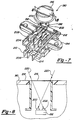
- Sensor 190 generally includes a single photodiode 192 mounted to housing 194 and covered by lens 196.
- Photodiode 192 includes a ceramic header 198, a left side photodiode die 200, and a right side photodiode die 202.
- Photodiode dies 200 and 202 again have a common cathode lead 204 which connects to common terminal 206, a left photodiode die anode lead 208 attached to a left side terminal 210, and a right photodiode die anode lead 212 connected to a right side terminal 214.
- photodiode 192 is positioned a known distance below a top surface 216 of lens 196.
- Top surface 216 is positioned so that it is generally coincident with an outer surface 218 of instrument panel 90 (shown in Fig. 3) such that when the azimuth of the sun is generally in the east the sunload projects onto the left side photodiode die as indicated by light ray 220.
- instrument panel 90 shown in Fig. 3
- the output signal created by left side photodiode die 200 would correspond to the second curve 98 of Figure 4 and the output signal from the right side photodiode die 202 would correspond to the first curve 96 in Figure 4.
Landscapes
- Life Sciences & Earth Sciences (AREA)
- Sustainable Development (AREA)
- Physics & Mathematics (AREA)
- Thermal Sciences (AREA)
- Engineering & Computer Science (AREA)
- Mechanical Engineering (AREA)
- Air-Conditioning For Vehicles (AREA)
- Photometry And Measurement Of Optical Pulse Characteristics (AREA)
- Air Conditioning Control Device (AREA)
Applications Claiming Priority (2)
| Application Number | Priority Date | Filing Date | Title |
|---|---|---|---|
| US741331 | 1985-06-05 | ||
| US08/741,331 US5957375A (en) | 1996-10-28 | 1996-10-28 | Sunload sensor for automatic climate control systems |
Publications (2)
| Publication Number | Publication Date |
|---|---|
| EP0852189A2 true EP0852189A2 (de) | 1998-07-08 |
| EP0852189A3 EP0852189A3 (de) | 2000-12-27 |
Family
ID=24980296
Family Applications (1)
| Application Number | Title | Priority Date | Filing Date |
|---|---|---|---|
| EP97118066A Withdrawn EP0852189A3 (de) | 1996-10-28 | 1997-10-17 | Sonnensensor zur automatischen Klimakontrolle |
Country Status (3)
| Country | Link |
|---|---|
| US (1) | US5957375A (de) |
| EP (1) | EP0852189A3 (de) |
| CA (1) | CA2216815A1 (de) |
Cited By (3)
| Publication number | Priority date | Publication date | Assignee | Title |
|---|---|---|---|---|
| EP1133679A4 (de) * | 1998-11-09 | 2003-07-02 | Control Devices Inc | Solarsensor mit zwei zonen |
| EP1097827A3 (de) * | 1999-11-05 | 2003-09-03 | Webasto Systemkomponenten GmbH & Co. KG | Belüftungsvorrichtung für einen Sitz eines Fahrzeugs |
| US7157678B2 (en) | 2003-06-24 | 2007-01-02 | Accel Ab | Optical radiation intensity sensor |
Families Citing this family (14)
| Publication number | Priority date | Publication date | Assignee | Title |
|---|---|---|---|---|
| WO1999024951A1 (en) * | 1997-11-12 | 1999-05-20 | Control Devices, Inc. | Solar radiation sensor |
| JP4122701B2 (ja) * | 2000-10-24 | 2008-07-23 | 株式会社デンソー | 日射センサ |
| US6454178B1 (en) | 2001-05-24 | 2002-09-24 | Ford Global Technologies, Inc. | Adaptive controller for an automotive HVAC system |
| CA2349093A1 (en) * | 2001-05-29 | 2002-11-29 | Silonex Inc. | Sunload sensor for automotive vehicules |
| DE10256645A1 (de) * | 2002-12-03 | 2004-06-17 | Hella Kg Hueck & Co. | Sensorvorrichtung |
| US20040217258A1 (en) * | 2003-04-30 | 2004-11-04 | Clugston P. Edward | Solar sensor including reflective element to transform the angular response |
| DE102005009120B4 (de) * | 2005-03-01 | 2009-03-12 | Preh Gmbh | Sensoranordnung im Kfz-Außenspiegel |
| USD519860S1 (en) | 2005-05-20 | 2006-05-02 | Bugbee Bruce G | Sensor housing |
| KR100654975B1 (ko) * | 2005-07-27 | 2006-12-08 | 현대모비스 주식회사 | 차량용 일사량감지센서 |
| US8694205B1 (en) | 2013-01-23 | 2014-04-08 | Ford Global Technologies, Llc | Multi-zone demist strategy |
| MX2017000641A (es) * | 2014-07-14 | 2017-04-27 | Delta T Corp | Sistema de control de comodidad termica integrado con control de sombreado. |
| KR102298884B1 (ko) * | 2017-02-14 | 2021-09-07 | 현대자동차주식회사 | 차량용 일사 감지 센서 조립체 및 이를 갖는 공조 시스템 |
| KR102777745B1 (ko) * | 2019-05-10 | 2025-03-06 | 현대자동차주식회사 | 포토 센서 구조 |
| KR20220167088A (ko) * | 2021-06-11 | 2022-12-20 | 현대자동차주식회사 | 공조 제어 장치 및 방법 |
Family Cites Families (23)
| Publication number | Priority date | Publication date | Assignee | Title |
|---|---|---|---|---|
| US3292050A (en) * | 1965-08-19 | 1966-12-13 | Gen Electric | Mounting of solid state electronic components |
| US3768059A (en) * | 1972-05-15 | 1973-10-23 | Barber Colman Co | Ambient compensated solar sensor |
| US4441405A (en) * | 1981-03-12 | 1984-04-10 | Nissan Motor Company, Limited | Solar radiation heat influx sensor for an automotive vehicle |
| AU557732B2 (en) * | 1981-05-09 | 1987-01-08 | Mori, K. | Sunlight direction sensor |
| US4491727A (en) * | 1981-07-01 | 1985-01-01 | Ramot University Authority For Applied Research | Solar radiation sensor and system including same for measuring solar radiation distribution |
| US4442801A (en) * | 1981-12-16 | 1984-04-17 | Glynn John D | Electrolysis fuel supplementation apparatus for combustion engines |
| US4629941A (en) * | 1985-01-07 | 1986-12-16 | Ellis Edward H | Differential illumination sensitive switching circuit |
| JPS63141816A (ja) * | 1986-12-03 | 1988-06-14 | Hitachi Ltd | 自動車用空調制御装置 |
| US4890460A (en) * | 1987-11-21 | 1990-01-02 | Diesel Kiki Co., Ltd. | Air conditioning apparatus for car |
| JP2554119B2 (ja) * | 1988-02-26 | 1996-11-13 | 株式会社日立製作所 | 自動車空調用日射センサー |
| DE3821743A1 (de) * | 1988-06-28 | 1990-01-11 | Bosch Gmbh Robert | Sensor zur erfassung der einstrahlung |
| SE462665B (sv) * | 1988-12-22 | 1990-08-06 | Saab Scania Ab | Givare till en klimatanlaeggning foer fordon |
| DE4024431C2 (de) * | 1989-08-03 | 1993-12-23 | Zexel Corp | Verfahren zur Steuerung einer Klimaanlage für ein Kraftfahrzeug |
| US5117643A (en) * | 1990-01-24 | 1992-06-02 | Zexel Corp. | Automobile air-conditioner |
| JP2778213B2 (ja) * | 1990-06-08 | 1998-07-23 | 株式会社デンソー | 車両用空調制御装置 |
| JPH0495728A (ja) * | 1990-08-07 | 1992-03-27 | Zexel Corp | 日射センサ |
| US5072106A (en) * | 1990-09-25 | 1991-12-10 | Zexel Corporation | Solar radiation quantity detecting device for automobile air-conditioner |
| JP3028580B2 (ja) * | 1990-10-04 | 2000-04-04 | 株式会社デンソー | 車両用空調装置 |
| JP3239378B2 (ja) * | 1991-08-09 | 2001-12-17 | 株式会社デンソー | 車両用空調装置 |
| JP3175237B2 (ja) * | 1991-10-08 | 2001-06-11 | 株式会社デンソー | 車両用空調装置 |
| US5344070A (en) * | 1993-01-07 | 1994-09-06 | Calsonic Corporation | Computer-controlled automotive air conditioning system with fuzzy inference |
| US5298732A (en) * | 1993-02-18 | 1994-03-29 | Emee, Inc. | Automatic visor for continuously repositioning a shading object to shade a designated location from a direct radiation source |
| JP3232828B2 (ja) * | 1993-11-25 | 2001-11-26 | 日産自動車株式会社 | 車両用冷房装置 |
-
1996
- 1996-10-28 US US08/741,331 patent/US5957375A/en not_active Expired - Fee Related
-
1997
- 1997-10-16 CA CA002216815A patent/CA2216815A1/en not_active Abandoned
- 1997-10-17 EP EP97118066A patent/EP0852189A3/de not_active Withdrawn
Cited By (5)
| Publication number | Priority date | Publication date | Assignee | Title |
|---|---|---|---|---|
| EP1133679A4 (de) * | 1998-11-09 | 2003-07-02 | Control Devices Inc | Solarsensor mit zwei zonen |
| EP1097827A3 (de) * | 1999-11-05 | 2003-09-03 | Webasto Systemkomponenten GmbH & Co. KG | Belüftungsvorrichtung für einen Sitz eines Fahrzeugs |
| US7157678B2 (en) | 2003-06-24 | 2007-01-02 | Accel Ab | Optical radiation intensity sensor |
| US7378628B2 (en) | 2003-06-24 | 2008-05-27 | Accel Ab | Photo radiation intensity sensor and method thereof |
| DE102004031907B4 (de) | 2003-06-24 | 2022-01-20 | Accel Ab | Optischer Strahlungsintensitätssensor mit einer lichtstreuenden Masse zwischen der Sensoröffnung und dem Sensorelement |
Also Published As
| Publication number | Publication date |
|---|---|
| EP0852189A3 (de) | 2000-12-27 |
| US5957375A (en) | 1999-09-28 |
| CA2216815A1 (en) | 1998-04-28 |
Similar Documents
| Publication | Publication Date | Title |
|---|---|---|
| US5957375A (en) | Sunload sensor for automatic climate control systems | |
| US4760772A (en) | Vehicle air-conditioning control apparatus | |
| US5553661A (en) | Solar position correction for climate control system | |
| US5072105A (en) | Solar radiation detecting device and automobile air-conditioner using the same | |
| US6575378B2 (en) | Solar radiation detection unit and vehicle air conditioner using the same | |
| US6681586B2 (en) | Vehicle air conditioner with adjusting function based on sunlight amount | |
| US20150025738A1 (en) | Methods and apparatus for automatic climate control in a vehicle based on clothing insulative factor | |
| JPH1067218A (ja) | 日射に関係して調整できる空気案内装置を備えた走行車の空調装置 | |
| US5072106A (en) | Solar radiation quantity detecting device for automobile air-conditioner | |
| US8011597B2 (en) | Auto A/C solar compensation control | |
| JP3232828B2 (ja) | 車両用冷房装置 | |
| JP4587591B2 (ja) | 車両用空調機の制御装置 | |
| KR101539434B1 (ko) | 개선된 일광 보정을 구비한 차량용 공기 조화 시스템 | |
| US6962196B2 (en) | Mode switching control device of vehicle air-conditioning apparatus | |
| US4961462A (en) | Control apparatus for automobile air-conditioners | |
| US20250269698A1 (en) | Automatic directional control of hvac outlets | |
| US5056421A (en) | Automobile air-conditioner | |
| JPH0615288B2 (ja) | 車両用空調装置 | |
| JP2000062431A (ja) | 自動車用空気調和装置 | |
| US11420498B2 (en) | Photo sensor structure | |
| US7530234B2 (en) | Method for air-conditioning a vehicle interior dependent on incident sunshine | |
| JPH0356090Y2 (de) | ||
| JP3024189B2 (ja) | 自動車用空調装置 | |
| JPH0710645B2 (ja) | 自動車用空調装置における日射方向検出装置 | |
| JPH051446Y2 (de) |
Legal Events
| Date | Code | Title | Description |
|---|---|---|---|
| PUAI | Public reference made under article 153(3) epc to a published international application that has entered the european phase |
Free format text: ORIGINAL CODE: 0009012 |
|
| AK | Designated contracting states |
Kind code of ref document: A2 Designated state(s): DE FR GB |
|
| AX | Request for extension of the european patent |
Free format text: AL;LT;LV;RO;SI |
|
| PUAL | Search report despatched |
Free format text: ORIGINAL CODE: 0009013 |
|
| AK | Designated contracting states |
Kind code of ref document: A3 Designated state(s): AT BE CH DE DK ES FI FR GB GR IE IT LI LU MC NL PT SE |
|
| AX | Request for extension of the european patent |
Free format text: AL;LT;LV;RO;SI |
|
| 17P | Request for examination filed |
Effective date: 20010523 |
|
| AKX | Designation fees paid |
Free format text: DE FR GB |
|
| STAA | Information on the status of an ep patent application or granted ep patent |
Free format text: STATUS: THE APPLICATION HAS BEEN WITHDRAWN |
|
| 18W | Application withdrawn |
Effective date: 20030207 |