EP0852192A1 - Gassack-Modul - Google Patents
Gassack-Modul Download PDFInfo
- Publication number
- EP0852192A1 EP0852192A1 EP97122429A EP97122429A EP0852192A1 EP 0852192 A1 EP0852192 A1 EP 0852192A1 EP 97122429 A EP97122429 A EP 97122429A EP 97122429 A EP97122429 A EP 97122429A EP 0852192 A1 EP0852192 A1 EP 0852192A1
- Authority
- EP
- European Patent Office
- Prior art keywords
- clamping element
- airbag module
- gas bag
- module according
- gas source
- Prior art date
- Legal status (The legal status is an assumption and is not a legal conclusion. Google has not performed a legal analysis and makes no representation as to the accuracy of the status listed.)
- Withdrawn
Links
- 238000007664 blowing Methods 0.000 claims description 21
- 239000000463 material Substances 0.000 claims description 6
- 230000002093 peripheral effect Effects 0.000 claims 1
- 229910000639 Spring steel Inorganic materials 0.000 description 2
- 238000002347 injection Methods 0.000 description 2
- 239000007924 injection Substances 0.000 description 2
- 239000002184 metal Substances 0.000 description 2
- 230000008878 coupling Effects 0.000 description 1
- 238000010168 coupling process Methods 0.000 description 1
- 238000005859 coupling reaction Methods 0.000 description 1
- 230000000694 effects Effects 0.000 description 1
- 238000004519 manufacturing process Methods 0.000 description 1
Images
Classifications
-
- B—PERFORMING OPERATIONS; TRANSPORTING
- B60—VEHICLES IN GENERAL
- B60R—VEHICLES, VEHICLE FITTINGS, OR VEHICLE PARTS, NOT OTHERWISE PROVIDED FOR
- B60R21/00—Arrangements or fittings on vehicles for protecting or preventing injuries to occupants or pedestrians in case of accidents or other traffic risks
- B60R21/02—Occupant safety arrangements or fittings, e.g. crash pads
- B60R21/16—Inflatable occupant restraints or confinements designed to inflate upon impact or impending impact, e.g. air bags
- B60R21/20—Arrangements for storing inflatable members in their non-use or deflated condition; Arrangement or mounting of air bag modules or components
- B60R21/217—Inflation fluid source retainers, e.g. reaction canisters; Connection of bags, covers, diffusers or inflation fluid sources therewith or together
-
- B—PERFORMING OPERATIONS; TRANSPORTING
- B60—VEHICLES IN GENERAL
- B60R—VEHICLES, VEHICLE FITTINGS, OR VEHICLE PARTS, NOT OTHERWISE PROVIDED FOR
- B60R21/00—Arrangements or fittings on vehicles for protecting or preventing injuries to occupants or pedestrians in case of accidents or other traffic risks
- B60R21/02—Occupant safety arrangements or fittings, e.g. crash pads
- B60R21/16—Inflatable occupant restraints or confinements designed to inflate upon impact or impending impact, e.g. air bags
- B60R21/26—Inflatable occupant restraints or confinements designed to inflate upon impact or impending impact, e.g. air bags characterised by the inflation fluid source or means to control inflation fluid flow
-
- F—MECHANICAL ENGINEERING; LIGHTING; HEATING; WEAPONS; BLASTING
- F16—ENGINEERING ELEMENTS AND UNITS; GENERAL MEASURES FOR PRODUCING AND MAINTAINING EFFECTIVE FUNCTIONING OF MACHINES OR INSTALLATIONS; THERMAL INSULATION IN GENERAL
- F16L—PIPES; JOINTS OR FITTINGS FOR PIPES; SUPPORTS FOR PIPES, CABLES OR PROTECTIVE TUBING; MEANS FOR THERMAL INSULATION IN GENERAL
- F16L33/00—Arrangements for connecting hoses to rigid members; Rigid hose-connectors, i.e. single members engaging both hoses
- F16L33/02—Hose-clips
- F16L33/03—Self-locking elastic clips
Definitions
- the invention relates to an airbag module with an airbag, which has an injection mouth, essentially one tubular, gas outlet having an outlet end and a fastening device by means of which the gas bag and the compressed gas source are coupled together.
- gas bags have become gas-tight to a compressed gas source coupled by one located inside the gas bag Frame part which surrounds the edge of the blowing mouth, attached to a sheet metal housing with screw connections in which the compressed gas source is located.
- the edge of the blowing mouth between the sheet metal housing and clamped the frame part is not only in manufacturing due to the numerous Parts complex, but it also requires assembly a lot of time to connect the parts together.
- the invention creates an airbag module in which the Airbag and the compressed gas source in a simple, quick way can be connected.
- the invention provides according to a further embodiment a gas bag module, which is a tubular adapter part has, which connects the gas bag with the compressed gas source.
- the gas bag is with its blowing mouth on the adapter part put up and with the fastening device in shape of an annular one that surrounds the edge of the blowing mouth, a radial force-generating clamping element gas-tight connected to the adapter part.
- Position of the compressed gas source varies relative to the blowing mouth be without large-volume additional housing parts required are.
- the gas bag is attached only via the easy-to-install clamping element.
- the outer surface of the part on which the Injection mouth is clamped i.e. either the compressed gas source or the adapter part, according to a preferred embodiment in the area of attack of the fastening device an annular groove.
- the cross-sectional shape of the annular groove Cross-sectional shape of the clamping element substantially adapted is. This is a kind of positive connection between the fastening device and the compressed gas source or the adapter part achievable.
- the tensioning elements usually have the shape of a Hose or pipe clamp.
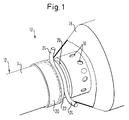
- a gas bag module 10 is shown in sections in FIG shown.
- the gas bag module 10 comprises a tubular one Pressurized gas source 12 with a bottle neck tapering Outlet end 14.
- the outlet end 14 has an end face closed free end with numerous outflow openings 16 in the outer surface.
- a gas bag 18 is included its blowing mouth 20 slipped onto the tubular outlet end 14.
- For a stable and gas-tight connection of the gas bag 18 at the outlet end 14 serves a fastening device in Shape of a clamping element 22. This is a more than 360 ° circularly bent wire made of spring steel, the free Ends 24 are angled radially outwards.
- a radial force on the outlet end 14 is the inside diameter of the annular clamping element 22 smaller than the outer diameter of the outlet end 14 in the range of Attack of the clamping element 22 so that the clamping element 22 in assembled state biased at the outlet end 14 and the boundary of the blowing mouth 20 gas-tight against the outlet end 14 presses.
- the outer surface of the Outlet end 14 has an annular groove 26 in which the clamping element 14 lies partially.
- the cross-sectional shape of the annular groove 26 is in their dimensions and their geometry of the cross-sectional shape of the clamping element 22 taking into account the thickness of the Gas bags 18 adapted in the area of the blowing mouth 22.
- the annular groove 26 a U-shaped cross section. A shift in the boundary of the gas bag mouth 20 on the outlet end 14 when unfolding of the gas bag 18 is by the on the side walls of the annular groove 26 adjacent clamping element 22 excluded.
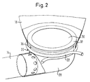
- the embodiment shown in Figure 2 corresponds to essential of that shown in Figure 1, which is why on the matching Parts that otherwise have the same reference numerals are not explicitly entered again must become.
- the gas bag 18 with its blowing mouth 20 an adapter part 28 angled approximately 90 ° in an L-shape and with the clamping element 22 on this gas-tight and positionally secure connected.
- the hollow adapter part 28 is in turn gastight and positionally secure on the outlet end 14 of the compressed gas source 12 attached.
- the flow cross-sectional area of the Adapter part 28 increases from the outlet end 14 assigned end up to the inside of the gas bag 18th projecting end 30 steadily, so that when the Gas from the compressed gas source 14 results in a diffuser effect.
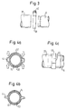
- FIGS. 3 to 6 Fastening devices are shown in FIGS. 3 to 6 shown.
- the clamping element 38 shown in Figure 3 is as Hose clamp executed, the edge of the blowing mouth 20 after putting on the outlet end 14 to this presses. Using a screw 40, the diameter the clamp varies.
- the tensioning element 42 shown in FIG. 4a is a continuous one Ring made of a deformable band material.
- the ring has two radially outwardly extending ones Bulges 44 provided that are diametrically opposite.
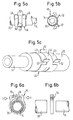
- the tensioning element 46 shown in FIGS. 5a to 5c consists of a circularly curved by more than 360 ° Spring steel band material. Because of the bend by more the ends of the strip material overlap in 360 ° Circumferential direction. A first end 48 splits in the overlap area in two end halves 48, between which the narrower second end in the overlap area 50 is included. Molded on the free ends, each form protrusions 52 projecting radially outwards, as in FIG the cross section shown in FIG. 5b indicated by the arrows, Force application points. Analogous to that in the figures 1 and 2, the clamping element 22 can have the ends 48, 50 towards each other, causing the inside diameter of the clamping element 46 is enlarged for assembly.
- the tensioning element 54 shown in FIGS. 6a and 6b in the form of a one-piece clamp has ends that are Split in the axial direction (see FIG. 6a) as a U-shape and each have teeth 56 which interlock. To reduce the diameter of the clamping element 54, the ends are as in FIG Arrows shown, moving towards each other.
- the one through the Teeth 56 formed ratchet-type quick release fastener allows easy moving of the ends in one Direction and prevents moving back due to the tooth shape the ends after assembly.
- the gas bag 18 can quickly and safely at the outlet end 14 or be mounted on the adapter part 28.
Landscapes
- Engineering & Computer Science (AREA)
- Mechanical Engineering (AREA)
- General Engineering & Computer Science (AREA)
- Physics & Mathematics (AREA)
- Fluid Mechanics (AREA)
- Air Bags (AREA)
- Buffer Packaging (AREA)
Abstract
Description
- Figur 1 einen Ausschnitt einer ersten Ausführungsform des erfindungsgemäßen Gassack-Moduls im Bereich der Befestigung des Gassacks an der Druckgasquelle;
- Figur 2 einen Ausschnitt einer zweiten Ausführungsform des erfindungsgemäßen Gassack-Moduls, bei dem der Gassack an einem abgewinkelten Adapterteil befestigt ist;
- Figur 3 eine Schelle, mit der der Gassack an der Druckgasquelle oder an dem Adapterteil befestigt werden kann;
- Figuren 4a bis 4c Schnittansichten und eine Seitenansicht eines deformierbaren durchgehenden Ringes, mit dem der Gassack an der Druckgasquelle oder an dem Adapterteil befestigt werden kann;
- Figuren 5a bis 5c verschiedene Ansichten eines Spannelements in Form eines um mehr als 360° gebogenen federelastischen Bandmaterials zur Befestigung des Gassacks; und
- Figuren 6a und 6b eine Schnittansicht bzw. eine Seitenansicht einer Schelle mit einem ratschenförmigen Schnellverschluß zur Befestigung des Gassacks.
Claims (10)
- Gassack-Modul miteinem Gassack (18), der einen Einblasmund (20) aufweist,einer im wesentlichen rohrförmigen, ein Auslaßende (14) aufweisenden Druckgasquelle (12) undeiner Befestigungseinrichtung, mittels der der Gassack (18) und die Druckgasquelle (12) miteinander gekoppelt sind,
dadurch gekennzeichnet, daß der Gassack (18) mit seinem Einblasmund (20) über das Auslaßende (14) gestülpt ist und mit der Befestigungseinrichtung in Form eines ringförmigen, die Berandung des Einblasmundes (20) umgebenden, eine radiale Kraft erzeugenden Spannelements (22; 38; 42; 46; 54) gasdicht an der Druckgasquelle (12) angeschlossen ist. - Gassack-Modul miteinem Gassack (18), der einen Einblasmund (20) aufweist,einer im wesentlichen rohrförmigen, ein Auslaßende (14) aufweisenden Druckgasquelle (12) undeiner Befestigungseinrichtung, mittels der der Gassack (18) und die Druckgasquelle (12) miteinander gekoppelt sind,
dadurch gekennzeichnet, daß ein rohrförmiges Adapterteil (28) den Gassack (18) mit der Druckgasquelle (12) verbindet, daß der Gassack (18) mit seinem Einblasmund (20) auf das Adapterteil (28) gestülpt ist und mit der Befestigungseinrichtung in Form eines ringförmigen, die Berandung des Einblasmundes (20) umgebenden, eine radiale Kraft erzeugenden Spannelements (22; 38; 42; 46; 54) gasdicht am Adapterteil angeschlossen ist. - Gassack-Modul nach Anspruch 2, dadurch gekennzeichnet, daß das Adapterteil (28) insgesamt abgewinkelt ist.
- Gassack-Modul nach einem der vorstehenden Ansprüche, dadurch gekennzeichnet, daß die äußere Mantelfläche desjenigen Teiles, auf das die Berandung des Einblasmundes (20) geklemmt ist, im Bereich des Angriffs der Befestigungseinrichtung eine Ringnut (26; 36) aufweist.
- Gassack-Modul nach Anspruch 4, dadurch gekennzeichnet, daß die Querschnittsform der Ringnut (26; 36) der Querschnittsform des Spannelements (22; 38; 42; 46; 54) im wesentlichen angepaßt ist.
- Gassack-Modul nach einem der vorstehenden Ansprüche, dadurch gekennzeichnet, daß das Spannelement (38) eine Schlauchschelle ist.
- Gassack-Modul nach einem der Ansprüche 1 bis 5, dadurch gekennzeichnet, daß das Spannelement (22) ein um mehr als 360° kreisringförmig gebogener, federelastischer Draht ist, dessen freie Enden (24) radial nach außen abgewinkelt sind.
- Gassack-Modul nach einem der Ansprüche 1 bis 5, dadurch gekennzeichnet, daß das Spannelement (42) ein durchgehender Ring aus Bandmaterial ist, welcher wenigstens ein Paar von diametral gegenüberliegenden, sich radial nach außen erstreckenden Ausbuchtungen (44) aufweist, die zur Verringerung des Innendurchmessers des Spannelements (42) verpreßt werden können.
- Gassack-Modul nach einem der Ansprüche 1 bis 5, dadurch gekennzeichnet, daß das Spannelement (46) ein um mehr als 360° kreisringförmig gebogenes Bandmaterial ist, dessen Enden (48, 50) sich in Umfangsrichtung überschneiden, wobei sich das erste freie Ende im Überschneidungsbereich aufspaltet und die entstehenden Endenhälften (48) das im Überschneidungsbereich schmale, zweite Ende (50) zwischen sich aufnehmen und wobei die freien Enden (48, 50) jeweils radial nach außen abstehende Vorsprünge (52) zum Aufbringen einer Umfangskraft aufweisen.
- Gassack-Modul nach einem der Ansprüche 1 bis 5, dadurch gekennzeichnet, daß das Spannelement (54) eine einteilige Schelle mit einem ratschenartigen Schnellverschluß ist.
Applications Claiming Priority (2)
| Application Number | Priority Date | Filing Date | Title |
|---|---|---|---|
| DE29622493U DE29622493U1 (de) | 1996-12-27 | 1996-12-27 | Gassack-Modul |
| DE29622493U | 1996-12-27 |
Publications (1)
| Publication Number | Publication Date |
|---|---|
| EP0852192A1 true EP0852192A1 (de) | 1998-07-08 |
Family
ID=8033855
Family Applications (1)
| Application Number | Title | Priority Date | Filing Date |
|---|---|---|---|
| EP97122429A Withdrawn EP0852192A1 (de) | 1996-12-27 | 1997-12-18 | Gassack-Modul |
Country Status (5)
| Country | Link |
|---|---|
| EP (1) | EP0852192A1 (de) |
| JP (1) | JPH10194068A (de) |
| KR (1) | KR19980064460A (de) |
| DE (1) | DE29622493U1 (de) |
| ES (1) | ES2124680T1 (de) |
Cited By (3)
| Publication number | Priority date | Publication date | Assignee | Title |
|---|---|---|---|---|
| DE10225032A1 (de) * | 2002-06-06 | 2004-01-08 | Autoliv Development Ab | Vorrichtung zum Befestigen eines Gassackeinfüllschlauches an einem Gasgenerator |
| EP2014961A1 (de) * | 2007-06-08 | 2009-01-14 | Delphi Technologies, Inc. | Flussregelventil |
| US20250128779A1 (en) * | 2021-09-24 | 2025-04-24 | Honda Motor Co., Ltd. | Airbag device for saddle-type vehicle |
Families Citing this family (9)
| Publication number | Priority date | Publication date | Assignee | Title |
|---|---|---|---|---|
| DE29702011U1 (de) * | 1997-02-05 | 1997-06-05 | Trw Occupant Restraint Systems Gmbh, 73551 Alfdorf | Baugruppe aus einem Gasgenerator und einem Abströmrohr für ein Fahrzeuginsassen-Rückhaltesystem |
| DE19737067C1 (de) * | 1997-08-26 | 1998-12-17 | Autoliv Dev | Gassackanordnung mit Schrumpffolien-Formteil zur Anbindung des Gasgenerators |
| DE10236905A1 (de) * | 2002-08-12 | 2004-02-26 | Trw Occupant Restraint Systems Gmbh & Co. Kg | Verfahren zur Befestigung einer Gaslanze an einem Gasgenerator und Baugruppe mit einem Gasgenerator und einer Gaslanze |
| KR100602674B1 (ko) | 2004-12-15 | 2006-07-20 | 현대모비스 주식회사 | 차량용 커튼 에어백 |
| DE102005024846B4 (de) * | 2005-05-27 | 2014-03-13 | Autoliv Development Ab | Gassack-Einheit |
| DE102006049429B4 (de) * | 2006-10-16 | 2015-12-31 | Autoliv Development Ab | Airbageinrichtung |
| DE102014200252A1 (de) | 2014-01-09 | 2014-04-10 | Takata AG | Gassackanordnung und Verfahren zur Herstellung einer Gassackanordnung |
| CN112260183A (zh) * | 2020-09-24 | 2021-01-22 | 中建八局轨道交通建设有限公司 | 充气式穿墙套管及其施工方法 |
| WO2025002558A1 (de) * | 2023-06-29 | 2025-01-02 | Zf Automotive Germany Gmbh | Modulgehäuse für ein gassackmodul eines fahrzeuginsassensicherheitssystems sowie gassackmodul, fahrzeuginsassensicherheitssystem und fahrzeug mit einem solchen modulgehäuse |
Citations (8)
| Publication number | Priority date | Publication date | Assignee | Title |
|---|---|---|---|---|
| US2614304A (en) * | 1951-06-01 | 1952-10-21 | Oetiker Hans | Hose clip |
| US2850291A (en) * | 1957-10-03 | 1958-09-02 | William B Jaspert | Protective devices for passengers in moving vehicles |
| US3706462A (en) * | 1970-05-28 | 1972-12-19 | Wallace B Lilly | Inflatable safety device |
| US3805337A (en) * | 1973-04-23 | 1974-04-23 | Raymond Lee Organization Inc | Spring wire hose clamp |
| EP0040258A1 (de) * | 1980-05-17 | 1981-11-25 | Harry Remih | Kunststoffschlauchschelle |
| US4380096A (en) * | 1981-07-13 | 1983-04-19 | Nissan Motor Co., Ltd. | Hose clamp |
| US5366241A (en) * | 1993-09-30 | 1994-11-22 | Kithil Philip W | Automobile air bag system |
| WO1996009193A1 (en) * | 1994-09-23 | 1996-03-28 | Kithil Philip W | Automobile air bag system |
-
1996
- 1996-12-27 DE DE29622493U patent/DE29622493U1/de not_active Expired - Lifetime
-
1997
- 1997-12-18 ES ES97122429T patent/ES2124680T1/es active Pending
- 1997-12-18 EP EP97122429A patent/EP0852192A1/de not_active Withdrawn
- 1997-12-22 KR KR1019970071792A patent/KR19980064460A/ko not_active Withdrawn
- 1997-12-26 JP JP9360848A patent/JPH10194068A/ja active Pending
Patent Citations (8)
| Publication number | Priority date | Publication date | Assignee | Title |
|---|---|---|---|---|
| US2614304A (en) * | 1951-06-01 | 1952-10-21 | Oetiker Hans | Hose clip |
| US2850291A (en) * | 1957-10-03 | 1958-09-02 | William B Jaspert | Protective devices for passengers in moving vehicles |
| US3706462A (en) * | 1970-05-28 | 1972-12-19 | Wallace B Lilly | Inflatable safety device |
| US3805337A (en) * | 1973-04-23 | 1974-04-23 | Raymond Lee Organization Inc | Spring wire hose clamp |
| EP0040258A1 (de) * | 1980-05-17 | 1981-11-25 | Harry Remih | Kunststoffschlauchschelle |
| US4380096A (en) * | 1981-07-13 | 1983-04-19 | Nissan Motor Co., Ltd. | Hose clamp |
| US5366241A (en) * | 1993-09-30 | 1994-11-22 | Kithil Philip W | Automobile air bag system |
| WO1996009193A1 (en) * | 1994-09-23 | 1996-03-28 | Kithil Philip W | Automobile air bag system |
Cited By (5)
| Publication number | Priority date | Publication date | Assignee | Title |
|---|---|---|---|---|
| DE10225032A1 (de) * | 2002-06-06 | 2004-01-08 | Autoliv Development Ab | Vorrichtung zum Befestigen eines Gassackeinfüllschlauches an einem Gasgenerator |
| DE10225032B4 (de) * | 2002-06-06 | 2006-02-09 | Autoliv Development Ab | Vorrichtung zum Befestigen eines Gassackeinfüllschlauches an einem Gasgenerator |
| EP2014961A1 (de) * | 2007-06-08 | 2009-01-14 | Delphi Technologies, Inc. | Flussregelventil |
| US20250128779A1 (en) * | 2021-09-24 | 2025-04-24 | Honda Motor Co., Ltd. | Airbag device for saddle-type vehicle |
| US12286186B1 (en) * | 2021-09-24 | 2025-04-29 | Honda Motor Co., Ltd. | Airbag device for saddle-type vehicle |
Also Published As
| Publication number | Publication date |
|---|---|
| ES2124680T1 (es) | 1999-02-16 |
| JPH10194068A (ja) | 1998-07-28 |
| KR19980064460A (ko) | 1998-10-07 |
| DE29622493U1 (de) | 1997-04-24 |
Similar Documents
| Publication | Publication Date | Title |
|---|---|---|
| DE69320833T2 (de) | Dichtungsvorrichtung auf einem rohr sowie dichtungsring dafür | |
| DE10123924B4 (de) | Rohrschelle, insbesondere Rohrkupplung | |
| DE3781891T2 (de) | Bandschelle mit uebergrossen spannschraubenloechern. | |
| EP0852192A1 (de) | Gassack-Modul | |
| DE19806235A1 (de) | Schellenanordnung | |
| DE7517047U (de) | Mindestens zweiteilige klammermuffe zum verbinden von zwei mit boerdeln versehene rohrenden | |
| WO1998048206A1 (de) | Rohrschelle | |
| DE69724392T2 (de) | Verfahren zum Verbinden von Rohren | |
| EP0728979A1 (de) | Abdichtende Verbindung eines Kunststoffrohres mit einem aus Metall gefertigten Anschlussstück | |
| DE19514940C1 (de) | Rohrkupplung | |
| EP0510369A1 (de) | Kupplungseinrichtung für ein Schlauchsystem | |
| EP3460307A1 (de) | Profilschelle mit dichtelement | |
| DE29921406U1 (de) | Steckarmatur zum schnellen und lösbaren Anschluß von Druckmittel-Leitungen | |
| EP1087172B1 (de) | Vorrichtung zum endseitigen Verschliessen eines Rohres | |
| WO2019201728A1 (de) | Strafferbaugruppe für einen gurtstraffer und verfahren zum herstellen einer strafferbaugruppe | |
| DE102016005301A1 (de) | Verbindungsvorrichtung, insbesondere in Form einer Schlauchkupplung | |
| DE3739626A1 (de) | Steckverbindung | |
| DE19960619A1 (de) | Anordnung zur Befestigung eines Flansches | |
| DE10302211A1 (de) | Schwingungsdämpfer | |
| DE4209795A1 (de) | Schlauchanschluß | |
| DE4103702C1 (de) | ||
| EP0822124A1 (de) | Gassack-Modul für ein Fahrzeuginsassen-Rückhaltesystem | |
| DE19731563A1 (de) | Verfahren zur Herstellung einer dichten und festen Rohrverbindung | |
| EP0122329B1 (de) | Ringförmige Schlauchklemme | |
| DE102004054336B4 (de) | Anordnung und Verfahren zum Verbinden von rohrförmigen Elementen |
Legal Events
| Date | Code | Title | Description |
|---|---|---|---|
| PUAI | Public reference made under article 153(3) epc to a published international application that has entered the european phase |
Free format text: ORIGINAL CODE: 0009012 |
|
| AK | Designated contracting states |
Kind code of ref document: A1 Designated state(s): DE ES FR GB IT |
|
| AX | Request for extension of the european patent |
Free format text: AL;LT;LV;MK;RO;SI |
|
| GBC | Gb: translation of claims filed (gb section 78(7)/1977) | ||
| 17P | Request for examination filed |
Effective date: 19981123 |
|
| EL | Fr: translation of claims filed | ||
| REG | Reference to a national code |
Ref country code: ES Ref legal event code: BA2A Ref document number: 2124680 Country of ref document: ES Kind code of ref document: T1 |
|
| AKX | Designation fees paid |
Free format text: DE ES FR GB IT |
|
| RBV | Designated contracting states (corrected) |
Designated state(s): DE ES FR GB IT |
|
| 17Q | First examination report despatched |
Effective date: 20020107 |
|
| STAA | Information on the status of an ep patent application or granted ep patent |
Free format text: STATUS: THE APPLICATION IS DEEMED TO BE WITHDRAWN |
|
| 18D | Application deemed to be withdrawn |
Effective date: 20020518 |