EP0852200A2 - Hydraulisch angetriebener Ventilator und Servolenkung in einem Fahrzeug - Google Patents
Hydraulisch angetriebener Ventilator und Servolenkung in einem Fahrzeug Download PDFInfo
- Publication number
- EP0852200A2 EP0852200A2 EP98100088A EP98100088A EP0852200A2 EP 0852200 A2 EP0852200 A2 EP 0852200A2 EP 98100088 A EP98100088 A EP 98100088A EP 98100088 A EP98100088 A EP 98100088A EP 0852200 A2 EP0852200 A2 EP 0852200A2
- Authority
- EP
- European Patent Office
- Prior art keywords
- fan
- fluid
- steering
- pressure
- valve
- Prior art date
- Legal status (The legal status is an assumption and is not a legal conclusion. Google has not performed a legal analysis and makes no representation as to the accuracy of the status listed.)
- Withdrawn
Links
Images


Classifications
-
- B—PERFORMING OPERATIONS; TRANSPORTING
- B62—LAND VEHICLES FOR TRAVELLING OTHERWISE THAN ON RAILS
- B62D—MOTOR VEHICLES; TRAILERS
- B62D5/00—Power-assisted or power-driven steering
- B62D5/06—Power-assisted or power-driven steering fluid, i.e. using a pressurised fluid for most or all the force required for steering a vehicle
- B62D5/07—Supply of pressurised fluid for steering also supplying other consumers ; control thereof
-
- F—MECHANICAL ENGINEERING; LIGHTING; HEATING; WEAPONS; BLASTING
- F15—FLUID-PRESSURE ACTUATORS; HYDRAULICS OR PNEUMATICS IN GENERAL
- F15B—SYSTEMS ACTING BY MEANS OF FLUIDS IN GENERAL; FLUID-PRESSURE ACTUATORS, e.g. SERVOMOTORS; DETAILS OF FLUID-PRESSURE SYSTEMS, NOT OTHERWISE PROVIDED FOR
- F15B11/00—Servomotor systems without provision for follow-up action; Circuits therefor
- F15B11/16—Servomotor systems without provision for follow-up action; Circuits therefor with two or more servomotors
-
- F—MECHANICAL ENGINEERING; LIGHTING; HEATING; WEAPONS; BLASTING
- F01—MACHINES OR ENGINES IN GENERAL; ENGINE PLANTS IN GENERAL; STEAM ENGINES
- F01P—COOLING OF MACHINES OR ENGINES IN GENERAL; COOLING OF INTERNAL-COMBUSTION ENGINES
- F01P7/00—Controlling of coolant flow
- F01P7/02—Controlling of coolant flow the coolant being cooling-air
- F01P7/04—Controlling of coolant flow the coolant being cooling-air by varying pump speed, e.g. by changing pump-drive gear ratio
- F01P7/044—Controlling of coolant flow the coolant being cooling-air by varying pump speed, e.g. by changing pump-drive gear ratio using hydraulic drives
-
- F—MECHANICAL ENGINEERING; LIGHTING; HEATING; WEAPONS; BLASTING
- F15—FLUID-PRESSURE ACTUATORS; HYDRAULICS OR PNEUMATICS IN GENERAL
- F15B—SYSTEMS ACTING BY MEANS OF FLUIDS IN GENERAL; FLUID-PRESSURE ACTUATORS, e.g. SERVOMOTORS; DETAILS OF FLUID-PRESSURE SYSTEMS, NOT OTHERWISE PROVIDED FOR
- F15B2211/00—Circuits for servomotor systems
- F15B2211/20—Fluid pressure source, e.g. accumulator or variable axial piston pump
- F15B2211/205—Systems with pumps
- F15B2211/2053—Type of pump
- F15B2211/20546—Type of pump variable capacity
- F15B2211/20553—Type of pump variable capacity with pilot circuit, e.g. for controlling a swash plate
-
- F—MECHANICAL ENGINEERING; LIGHTING; HEATING; WEAPONS; BLASTING
- F15—FLUID-PRESSURE ACTUATORS; HYDRAULICS OR PNEUMATICS IN GENERAL
- F15B—SYSTEMS ACTING BY MEANS OF FLUIDS IN GENERAL; FLUID-PRESSURE ACTUATORS, e.g. SERVOMOTORS; DETAILS OF FLUID-PRESSURE SYSTEMS, NOT OTHERWISE PROVIDED FOR
- F15B2211/00—Circuits for servomotor systems
- F15B2211/20—Fluid pressure source, e.g. accumulator or variable axial piston pump
- F15B2211/255—Flow control functions
-
- F—MECHANICAL ENGINEERING; LIGHTING; HEATING; WEAPONS; BLASTING
- F15—FLUID-PRESSURE ACTUATORS; HYDRAULICS OR PNEUMATICS IN GENERAL
- F15B—SYSTEMS ACTING BY MEANS OF FLUIDS IN GENERAL; FLUID-PRESSURE ACTUATORS, e.g. SERVOMOTORS; DETAILS OF FLUID-PRESSURE SYSTEMS, NOT OTHERWISE PROVIDED FOR
- F15B2211/00—Circuits for servomotor systems
- F15B2211/40—Flow control
- F15B2211/405—Flow control characterised by the type of flow control means or valve
- F15B2211/40515—Flow control characterised by the type of flow control means or valve with variable throttles or orifices
-
- F—MECHANICAL ENGINEERING; LIGHTING; HEATING; WEAPONS; BLASTING
- F15—FLUID-PRESSURE ACTUATORS; HYDRAULICS OR PNEUMATICS IN GENERAL
- F15B—SYSTEMS ACTING BY MEANS OF FLUIDS IN GENERAL; FLUID-PRESSURE ACTUATORS, e.g. SERVOMOTORS; DETAILS OF FLUID-PRESSURE SYSTEMS, NOT OTHERWISE PROVIDED FOR
- F15B2211/00—Circuits for servomotor systems
- F15B2211/40—Flow control
- F15B2211/42—Flow control characterised by the type of actuation
- F15B2211/426—Flow control characterised by the type of actuation electrically or electronically
-
- F—MECHANICAL ENGINEERING; LIGHTING; HEATING; WEAPONS; BLASTING
- F15—FLUID-PRESSURE ACTUATORS; HYDRAULICS OR PNEUMATICS IN GENERAL
- F15B—SYSTEMS ACTING BY MEANS OF FLUIDS IN GENERAL; FLUID-PRESSURE ACTUATORS, e.g. SERVOMOTORS; DETAILS OF FLUID-PRESSURE SYSTEMS, NOT OTHERWISE PROVIDED FOR
- F15B2211/00—Circuits for servomotor systems
- F15B2211/40—Flow control
- F15B2211/45—Control of bleed-off flow, e.g. control of bypass flow to the return line
-
- F—MECHANICAL ENGINEERING; LIGHTING; HEATING; WEAPONS; BLASTING
- F15—FLUID-PRESSURE ACTUATORS; HYDRAULICS OR PNEUMATICS IN GENERAL
- F15B—SYSTEMS ACTING BY MEANS OF FLUIDS IN GENERAL; FLUID-PRESSURE ACTUATORS, e.g. SERVOMOTORS; DETAILS OF FLUID-PRESSURE SYSTEMS, NOT OTHERWISE PROVIDED FOR
- F15B2211/00—Circuits for servomotor systems
- F15B2211/50—Pressure control
- F15B2211/505—Pressure control characterised by the type of pressure control means
- F15B2211/50509—Pressure control characterised by the type of pressure control means the pressure control means controlling a pressure upstream of the pressure control means
- F15B2211/50518—Pressure control characterised by the type of pressure control means the pressure control means controlling a pressure upstream of the pressure control means using pressure relief valves
-
- F—MECHANICAL ENGINEERING; LIGHTING; HEATING; WEAPONS; BLASTING
- F15—FLUID-PRESSURE ACTUATORS; HYDRAULICS OR PNEUMATICS IN GENERAL
- F15B—SYSTEMS ACTING BY MEANS OF FLUIDS IN GENERAL; FLUID-PRESSURE ACTUATORS, e.g. SERVOMOTORS; DETAILS OF FLUID-PRESSURE SYSTEMS, NOT OTHERWISE PROVIDED FOR
- F15B2211/00—Circuits for servomotor systems
- F15B2211/50—Pressure control
- F15B2211/55—Pressure control for limiting a pressure up to a maximum pressure, e.g. by using a pressure relief valve
-
- F—MECHANICAL ENGINEERING; LIGHTING; HEATING; WEAPONS; BLASTING
- F15—FLUID-PRESSURE ACTUATORS; HYDRAULICS OR PNEUMATICS IN GENERAL
- F15B—SYSTEMS ACTING BY MEANS OF FLUIDS IN GENERAL; FLUID-PRESSURE ACTUATORS, e.g. SERVOMOTORS; DETAILS OF FLUID-PRESSURE SYSTEMS, NOT OTHERWISE PROVIDED FOR
- F15B2211/00—Circuits for servomotor systems
- F15B2211/60—Circuit components or control therefor
- F15B2211/63—Electronic controllers
- F15B2211/6303—Electronic controllers using input signals
- F15B2211/6306—Electronic controllers using input signals representing a pressure
- F15B2211/6309—Electronic controllers using input signals representing a pressure the pressure being a pressure source supply pressure
-
- F—MECHANICAL ENGINEERING; LIGHTING; HEATING; WEAPONS; BLASTING
- F15—FLUID-PRESSURE ACTUATORS; HYDRAULICS OR PNEUMATICS IN GENERAL
- F15B—SYSTEMS ACTING BY MEANS OF FLUIDS IN GENERAL; FLUID-PRESSURE ACTUATORS, e.g. SERVOMOTORS; DETAILS OF FLUID-PRESSURE SYSTEMS, NOT OTHERWISE PROVIDED FOR
- F15B2211/00—Circuits for servomotor systems
- F15B2211/60—Circuit components or control therefor
- F15B2211/63—Electronic controllers
- F15B2211/6303—Electronic controllers using input signals
- F15B2211/6343—Electronic controllers using input signals representing a temperature
-
- F—MECHANICAL ENGINEERING; LIGHTING; HEATING; WEAPONS; BLASTING
- F15—FLUID-PRESSURE ACTUATORS; HYDRAULICS OR PNEUMATICS IN GENERAL
- F15B—SYSTEMS ACTING BY MEANS OF FLUIDS IN GENERAL; FLUID-PRESSURE ACTUATORS, e.g. SERVOMOTORS; DETAILS OF FLUID-PRESSURE SYSTEMS, NOT OTHERWISE PROVIDED FOR
- F15B2211/00—Circuits for servomotor systems
- F15B2211/60—Circuit components or control therefor
- F15B2211/66—Temperature control methods
-
- F—MECHANICAL ENGINEERING; LIGHTING; HEATING; WEAPONS; BLASTING
- F15—FLUID-PRESSURE ACTUATORS; HYDRAULICS OR PNEUMATICS IN GENERAL
- F15B—SYSTEMS ACTING BY MEANS OF FLUIDS IN GENERAL; FLUID-PRESSURE ACTUATORS, e.g. SERVOMOTORS; DETAILS OF FLUID-PRESSURE SYSTEMS, NOT OTHERWISE PROVIDED FOR
- F15B2211/00—Circuits for servomotor systems
- F15B2211/70—Output members, e.g. hydraulic motors or cylinders or control therefor
- F15B2211/705—Output members, e.g. hydraulic motors or cylinders or control therefor characterised by the type of output members or actuators
- F15B2211/7051—Linear output members
- F15B2211/7053—Double-acting output members
- F15B2211/7054—Having equal piston areas
-
- F—MECHANICAL ENGINEERING; LIGHTING; HEATING; WEAPONS; BLASTING
- F15—FLUID-PRESSURE ACTUATORS; HYDRAULICS OR PNEUMATICS IN GENERAL
- F15B—SYSTEMS ACTING BY MEANS OF FLUIDS IN GENERAL; FLUID-PRESSURE ACTUATORS, e.g. SERVOMOTORS; DETAILS OF FLUID-PRESSURE SYSTEMS, NOT OTHERWISE PROVIDED FOR
- F15B2211/00—Circuits for servomotor systems
- F15B2211/70—Output members, e.g. hydraulic motors or cylinders or control therefor
- F15B2211/705—Output members, e.g. hydraulic motors or cylinders or control therefor characterised by the type of output members or actuators
- F15B2211/7058—Rotary output members
Definitions
- the invention concerns a hydraulically powered fan for a radiator in a motor vehicle which shares a hydraulic power source with a power steering system.
- a fan In automotive vehicles, a fan commonly removes heat from liquid coolant, by pumping air over a heat exchanger, or radiator, through which the coolant flows.
- the fan is commonly driven directly by the engine, through a power-transmission belt.
- fan speed is linked to engine speed: as engine speed increases, the fan speed also increases.
- vehicle speed also generally increases. Increased vehicle speed increases the ram air flow through the radiator, which also cools the coolant, thereby reducing the need for fan cooling.
- the fan runs at a high speed, but is not needed.
- Some fans are equipped with a clutch, which disengages them from the engine, at high engine speeds, to solve this problem.
- fans are noisy. Each fan blade, as it passes an observer, delivers a small pressure pulse to the observer. As fan speed increases, the number of blade-passes occurring per second also increases, thereby increasing the number of pulses per second. That is, pulse frequency increases as fan speed increases. In addition, the magnitude of the pulses also increases as speed increases. Thus, a high-speed fan acts as a loud, high-frequency, noise source.
- crankshaft In a transversely mounted engine, the crankshaft is perpendicular to the direction of travel. However, the cooling face of the radiator is preferably perpendicular to the ram air stream, which is parallel to the direction of travel. If the disc representing the fan blades is parallel to the cooling surface of the radiator, then the fan's rotational axis is perpendicular to the crankshaft, causing complexity in transferring power from the crankshaft to the fan.
- An object of the invention is to provide an improved cooling system in an automotive vehicle.
- Another object of the invention is to provide a cooling system for an automotive vehicle in which power extracted from the engine, to power a cooling fan, is decreased as engine speed increases.
- the invention comprises a motor vehicle, powered by an engine, the improvement consisting of a variable displacement hydraulic pump, powered by the engine, a cooling system, for cooling the engine, and a power steering system, which are in fluidic series connection and receive fluid from the pump.
- this invention comprises a motor vehicle, powered by an engine, the improvement consisting of a constant displacement hydraulic pump, powered by the engine, a cooling system, comprising a hydraulic motor, for cooling the engine, and a power steering system, which systems are in fluidic series connection, and receive fluid from the pump; and a system for decreasing a hydraulic input to a fan motor when a system pressure rises.
- this invention comprises a system consisting of a constant-displacement pump system, powered by the engine, for producing a constant volumetric rate of pressurized fluid, independent of engine speed, a fan system comprising an input line and an output line, a fan motor, a pressure relief valve, and a speed control valve, all connected in parallel between the input line and the output line, a power steering system in series with the fan system for receiving fluid from the output line, and comprising a steering valve which controls fluid delivery to a steering rack and a relief valve in parallel with the steering valve, a line for recovering fluid from the power steering system and delivering the fluid to a sump which supplies the constant displacement pump system, and a sensor for causing the speed control valve to bypass fluid from the motor when input pressure to the steering valve falls below a threshold.
- a constant-displacement pump system powered by the engine, for producing a constant volumetric rate of pressurized fluid, independent of engine speed
- a fan system comprising an input line and an output line, a fan motor, a pressure relief valve
- a vehicle displacement pump delivers hydraulic fluid in series to a cooling fan and a power steering pump in an automotive vehicle. If flow to the power steering pump falls short of its needs, a bypass flow to the cooling fan is shunted to the power steering pump.
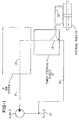
- FIG. 1 illustrates a simplified schematic view of one form of the invention.
- a hydraulic pump 3 delivers pressurized fluid along line 6 to a fan system 9.
- the fan system 9 extracts energy from the pressurized fluid, to drive a fan motor (not shown), which cools engine coolant (not shown).
- the fan system 9 is in series-flow arrangement with a power steering system 12. That is, as indicated by arrow 15, all fluid entering the fan system 9 is received by the power steering system 12.
- all fluid received by the power steering system 12 is delivered to line 18, which leads to a reservoir or sump 21, which feeds the pump 3.
- the power steering system 12 is also in series-flow arrangement with the sump 21. That is, all fluid entering the power steering system 12 from the fan system 9 enters line 18, either (1) directly, as indicated by arrow 19, or (2) indirectly, by first making an excursion through the steering rack 24, as indicated by arrow 20.
- the pump 3 is preferably a hydraulic pump of the variable displacement type, meaning that the flow rate of the pump (e.g., in gallons per minute) can be controlled. This control is exercised by a flow compensation valve 30.
- the flow compensation valve 30 is set to maintain a constant volumetric flow through line 6, to the fan system 9.
- the valve 30 accomplishes this constant flow by adjusting the displacement of pump 3.
- Such valves are known in the art.
- Line 6 feeds three components within the fan system 9, in parallel-flow arrangement, namely, a hydraulic fan speed control 33, a pressure relief valve 36, and a hydraulic fan motor 39, which drives a fan indicated by curved arrow 75.
- the relief valve 36 is ordinarily closed, unless an over-pressure condition is present. Normally, no over-pressure condition exists.
- the fan speed control 33 in effect, is a variable-aperture valve, which allows fluid to bypass the fan motor 39. Operation of the fan system can, conceptually, be divided into three modes (assuming the relief valve 36 to remain closed):
- an inlet branch 51 of the power steering system 12 may be coupled to hydraulic pressure sensor 80 which represents a pressure tap discussed later herein. However, no significant flow runs through this branch 51.
- the power steering system 12 contains two elements in parallel, namely, a hydraulic pressure relief valve 54 and a hydraulic steering valve 58, which controls steering of the vehicle (not shown). Ordinarily, the relief valve 54 is closed. Steering valve 58 controls fluid delivery to the two lines 60 and 63 leading to the steering rack 24.
- Lines 60 and 63 are in series, with respect to fluid which they deliver to the steering rack 24. That is, assuming the relief valve 54 to be closed, the algebraic sum of the flow through lines 60, 63, and 66 equals the flow entering the power steering system 12 on line 48. With this understanding, the operation of valve 58 can also be divided into three modes.
- Valve 58 can deliver some fluid (possibly zero in amount) to line 60, and pass some fluid to line 66.
- the flow rate in line 60 can be designated F60.
- the returning flow, in line 63 and designated F63, is the negative of F60.
- Mode 2 This mode is the opposite of mode 1.
- Valve 58 can deliver some fluid (possibly zero in amount) to line 63 and pass some fluid to line 66.
- F60 is the negative of F63.
- Mode 3 In this mode, no fluid is delivered to either line 60 or 63. All incoming fluid from line 48 is delivered to line 66 via relief value 54.
- both loads in this case the fan systems 9 and the steering system 12 are in series.
- the pressure at the pump 3 outline line 6 is the sum of the two loads.
- the fan motor 39 maximum capacity produces a pressure of 1600 psi
- the steering rack 24 maximum capability is 1450 psi
- the total load is their sum, 3050 psi.
- pressure sensor 80 limits the flow directed to the fan motor 39 by actuating fan speed control 33.
- the pump 3 maximum pressure capability is 2000 psi
- sensor 80 senses pressure and actuates fan speed control 33 to direct 1450 psi to steering system 12.
- the fan system 9 would be limited to 550 psi because the pump 3 is a variable displacement pump which provides a substantially constant flow.
- the flow compensation valve 30 causes the pump 3 to produce a constant volumetric flow, irrespective of engine speed. Constant-flow pump systems are known in the art.
- the fan motor 39 is designed to produce maximum cooling when this entire flow is delivered to the fan motor 39, as occurs when the fan speed control 33 is fully closed.
- a constant flow is delivered to line 6 and then a selected amount is delivered to the fan motor 39 by fan speed control 33.
- the selected amount controls the amount of cooling produced by the fan motor 39.
- the selected amount of hydraulic flow controls the amount, and velocity, of air which is pumped by the fan itself, represented by fan blades 75. Yet the volumetric flow rate of fluid delivered to the power steering system 12 remains constant.
- relief valves 36 and 54 are open, the serial flow arrangement of the fan system 9 and the power steering system 12 does not change. That is, if relief valve 36 opens, all flow entering the fan system 9, indicated by arrow 15 in Figure 1, still reaches the power steering system 12, although fan-cooling may be either less or disrupted. In addition, if relief valve 54 in Figure 2 opens, all fluid entering the power steering system 12 on line 48 is still delivered to sump 21 through line 18, although power-steering operation may be disrupted.
- the hydraulic pressure sensor 80 in Figure 2 can be provided.
- This sensor 80 produces a hydraulic signal when the pressure in line 48 reaches a predetermined minimum value.
- This signal is fed to the fan speed control 33 on line 83.
- This signal causes the fan speed control 33 to open fully, thereby diverting flow from the fan motor 39 and to the power steering system 12.
- This operation gives priority to the power steering system 12, when pressure in line 48 increases to the maximum value, under the rationale that in this situation power steering is more important than engine cooling.
- the combination of sensor 80 and speed control 33 monitors the input pressure, on line 48, to the power steering system 12 and, when the input pressure rises above a threshold, raises that pressure, by diverting flow away from fan motor 39. This diversion eliminates, or reduces, the pressure drop occurring in fan motor 39, and delivers the full pressure in line 6 to the power steering system 12, subject to the drop occurring in speed control 33.
- the sensor 80 need not measure pressure in line 48, even though that pressure is the input pressure to the power steering system 12.
- Other pressures in the hydraulic circuit of Figure 2 are related to that input pressure and can be used instead.
- the sensor 80 need not cause the ON/OFF operation just described. Instead, the sensor 80 can produce a scheduled signal, as indicated in Figure 3.
- the sensor 80 in Figure 2 produces an override signal SIG1 in Figure 3, which causes the fan speed control 33 in Figure 2 to fully open, thereby reducing the flow to fan motor 39.
- sensor 80 provides an override signal in response to pressure on line 48. This, in turn, controls the speed control 33 to direct more or less flow to fan motor 39.
- Fig. 3 shows a graph of the maximum flow allowed to motor 39 as a function of steering pressure. It should be appreciated that in the embodiment being described, the maximum pump 3 pressure may be in excess of a maximum steering pressure required by pressure relief valve 54. In this case, the difference in these pressures would be available to fan motor 39.
- the displacement feature of the combination of pump 3 and compensation valve 30 is significant because the combination holds volumetric flow constant, irrespective of engine speed. If flow were not held constant, then as engine speed increased, flow would increase, creating excess, unneeded flow, thereby wasting energy.
- the constant flow rate is designed such that, at engine idle, sufficient energy is produced to enable the power steering system 12 to turn the wheels of a stationary vehicle, standing on dry pavement, when the steering wheel is turned at a nominal speed, such as one revolution per second. (A greater steering wheel speed requires more energy to turn the wheels of the vehicle.)
- this constant flow is designed to deliver sufficient energy to the fan motor 39, to provide sufficient cooling on a hot (e.g., 100° F) day to the stationary vehicle.
Landscapes
- Engineering & Computer Science (AREA)
- Mechanical Engineering (AREA)
- Physics & Mathematics (AREA)
- Fluid Mechanics (AREA)
- General Engineering & Computer Science (AREA)
- Chemical & Material Sciences (AREA)
- Combustion & Propulsion (AREA)
- Transportation (AREA)
- Power Steering Mechanism (AREA)
- Steering Control In Accordance With Driving Conditions (AREA)
- Auxiliary Drives, Propulsion Controls, And Safety Devices (AREA)
Applications Claiming Priority (2)
| Application Number | Priority Date | Filing Date | Title |
|---|---|---|---|
| US77977197A | 1997-01-07 | 1997-01-07 | |
| US779771 | 1997-01-07 |
Publications (2)
| Publication Number | Publication Date |
|---|---|
| EP0852200A2 true EP0852200A2 (de) | 1998-07-08 |
| EP0852200A3 EP0852200A3 (de) | 2000-03-22 |
Family
ID=25117508
Family Applications (1)
| Application Number | Title | Priority Date | Filing Date |
|---|---|---|---|
| EP98100088A Withdrawn EP0852200A3 (de) | 1997-01-07 | 1998-01-07 | Hydraulisch angetriebener Ventilator und Servolenkung in einem Fahrzeug |
Country Status (1)
| Country | Link |
|---|---|
| EP (1) | EP0852200A3 (de) |
Cited By (2)
| Publication number | Priority date | Publication date | Assignee | Title |
|---|---|---|---|---|
| WO2013102536A1 (de) | 2012-01-04 | 2013-07-11 | Schusterjungen Und Hurenkinder Gmbh | Vorrichtung zur ausgabe kostenfreier muster |
| JP2017136887A (ja) * | 2016-02-01 | 2017-08-10 | 株式会社Kcm | 作業機械 |
Citations (1)
| Publication number | Priority date | Publication date | Assignee | Title |
|---|---|---|---|---|
| US5535845A (en) | 1995-03-09 | 1996-07-16 | Itt Automotive Electrical Systems, Inc. | Automotive hydraulic system and method |
Family Cites Families (2)
| Publication number | Priority date | Publication date | Assignee | Title |
|---|---|---|---|---|
| US4446697A (en) * | 1978-05-18 | 1984-05-08 | Eaton Corporation | Hydraulic fan drive system including variable displacement pump |
| US4738330A (en) * | 1985-03-22 | 1988-04-19 | Nippondenso Co., Ltd. | Hydraulic drive system for use with vehicle power steering pump |
-
1998
- 1998-01-07 EP EP98100088A patent/EP0852200A3/de not_active Withdrawn
Patent Citations (2)
| Publication number | Priority date | Publication date | Assignee | Title |
|---|---|---|---|---|
| US5535845A (en) | 1995-03-09 | 1996-07-16 | Itt Automotive Electrical Systems, Inc. | Automotive hydraulic system and method |
| US5669461A (en) | 1995-03-09 | 1997-09-23 | Itt Automotive Electrical Systems, Inc. | Automotive hydraulic system and method |
Cited By (2)
| Publication number | Priority date | Publication date | Assignee | Title |
|---|---|---|---|---|
| WO2013102536A1 (de) | 2012-01-04 | 2013-07-11 | Schusterjungen Und Hurenkinder Gmbh | Vorrichtung zur ausgabe kostenfreier muster |
| JP2017136887A (ja) * | 2016-02-01 | 2017-08-10 | 株式会社Kcm | 作業機械 |
Also Published As
| Publication number | Publication date |
|---|---|
| EP0852200A3 (de) | 2000-03-22 |
Similar Documents
| Publication | Publication Date | Title |
|---|---|---|
| US6360537B1 (en) | System for controlling a hydraulic vehicle drive | |
| US4680928A (en) | Warm-up promotion device for automatic transmission | |
| EP0946383B1 (de) | Hydraulischer lüftermotor und hydraulische lenkeintrichtung für ein kraftfahrzeug | |
| EP0792411B1 (de) | Hydraulikmotorsystem | |
| US4539943A (en) | Engine cooling system | |
| EP0812280B1 (de) | Hydraulisches system für ein fahrzeug und verfahren dafür | |
| RU2314946C2 (ru) | Приводной узел с тормозом-замедлителем | |
| FR2764348A1 (fr) | Ensemble d'entrainement hydraulique pour assister des fonctions auxiliaires dans des vehicules motorises, et procede pour ajuster en continu le refoulement d'une pompe pour un dispositif auxiliaire | |
| CA1321527C (en) | Hydraulic control device for a continuously variable transmission for motor vehicles | |
| US5178238A (en) | Hydrostatic braking power converter | |
| HUT59347A (en) | Hydrostatic torque-transmitting system | |
| US7022044B2 (en) | Drive train for powering a mobile vehicle | |
| US20160116060A1 (en) | Hydrostatic braking concept | |
| US6817455B1 (en) | Retarder system | |
| US6561324B2 (en) | Drive unit including a motor and a retarder | |
| EP0852200A2 (de) | Hydraulisch angetriebener Ventilator und Servolenkung in einem Fahrzeug | |
| US9482246B2 (en) | Hydrostatic drive | |
| WO1998028179A1 (en) | Hydraulically powered fan and power steering in a vehicle | |
| EP1092611B1 (de) | Hydrostatische Fahrzeuglenkung mit Zusatzpumpe | |
| US12169017B2 (en) | Vehicle transmission with a power take-off, vehicle and working machine arrangement | |
| US20040192505A1 (en) | Method for the operation of a drive train for powering a mobile vehicle | |
| US4480962A (en) | Pump with inlet passages downstream and through its flow control valve | |
| US7143862B2 (en) | Power steering device for a vehicle | |
| EP0999385A2 (de) | Hydrostatisches Getriebe für Traktoren | |
| JP3487090B2 (ja) | ポンプ/モータの冷却回路 |
Legal Events
| Date | Code | Title | Description |
|---|---|---|---|
| PUAI | Public reference made under article 153(3) epc to a published international application that has entered the european phase |
Free format text: ORIGINAL CODE: 0009012 |
|
| AK | Designated contracting states |
Kind code of ref document: A2 Designated state(s): DE FR GB |
|
| AX | Request for extension of the european patent |
Free format text: AL;LT;LV;MK;RO;SI |
|
| PUAL | Search report despatched |
Free format text: ORIGINAL CODE: 0009013 |
|
| AK | Designated contracting states |
Kind code of ref document: A3 Designated state(s): AT BE CH DE DK ES FI FR GB GR IE IT LI LU MC NL PT SE |
|
| AX | Request for extension of the european patent |
Free format text: AL;LT;LV;MK;RO;SI |
|
| 17P | Request for examination filed |
Effective date: 20000922 |
|
| AKX | Designation fees paid |
Free format text: DE FR GB |
|
| 17Q | First examination report despatched |
Effective date: 20020610 |
|
| STAA | Information on the status of an ep patent application or granted ep patent |
Free format text: STATUS: THE APPLICATION IS DEEMED TO BE WITHDRAWN |
|
| 18D | Application deemed to be withdrawn |
Effective date: 20021221 |