EP0852277A2 - Druckbacke für eine Spannvorrichtung - Google Patents
Druckbacke für eine Spannvorrichtung Download PDFInfo
- Publication number
- EP0852277A2 EP0852277A2 EP98100098A EP98100098A EP0852277A2 EP 0852277 A2 EP0852277 A2 EP 0852277A2 EP 98100098 A EP98100098 A EP 98100098A EP 98100098 A EP98100098 A EP 98100098A EP 0852277 A2 EP0852277 A2 EP 0852277A2
- Authority
- EP
- European Patent Office
- Prior art keywords
- pressure jaw
- pressure
- flooring
- jaw
- short leg
- Prior art date
- Legal status (The legal status is an assumption and is not a legal conclusion. Google has not performed a legal analysis and makes no representation as to the accuracy of the status listed.)
- Withdrawn
Links
Images
Classifications
-
- E—FIXED CONSTRUCTIONS
- E04—BUILDING
- E04F—FINISHING WORK ON BUILDINGS, e.g. STAIRS, FLOORS
- E04F21/00—Implements for finishing work on buildings
- E04F21/20—Implements for finishing work on buildings for laying flooring
- E04F21/22—Implements for finishing work on buildings for laying flooring of single elements, e.g. flooring cramps ; flexible webs
-
- Y—GENERAL TAGGING OF NEW TECHNOLOGICAL DEVELOPMENTS; GENERAL TAGGING OF CROSS-SECTIONAL TECHNOLOGIES SPANNING OVER SEVERAL SECTIONS OF THE IPC; TECHNICAL SUBJECTS COVERED BY FORMER USPC CROSS-REFERENCE ART COLLECTIONS [XRACs] AND DIGESTS
- Y10—TECHNICAL SUBJECTS COVERED BY FORMER USPC
- Y10T—TECHNICAL SUBJECTS COVERED BY FORMER US CLASSIFICATION
- Y10T29/00—Metal working
- Y10T29/53—Means to assemble or disassemble
- Y10T29/53961—Means to assemble or disassemble with work-holder for assembly
Definitions
- the invention relates to a pressure jaw for a clamping device.
- the Pressure jaw forms one end of the clamping device for floating flooring to be laid, such as laminates and finished parquet several strips to be joined in parallel by means of tongue and groove Flooring slabs.
- the jig another pressure jaw is arranged and by means of both pressure jaws a series of flooring slabs are pressed together.
- Laminates and finished parquet differ in the material thickness as well as in the format, are also different Manufacturers regarding the external dimensions as well as the groove and Feather dimensioned differently and consist of a carrier material and a wear layer made of other wood that forms the surface, that are not damaged when using the clamping devices may. Also the tongue to be inserted into the groove of a subsequent plate at the edge of the plate by applying pressure to a tensioning device not be deformed because of making a clean plate connection would then no longer be possible.
- the present invention was therefore based on the object of a pressure jaw for creating a jig that is for floating laying of flooring plates and in which the pressure jaw at Laying of laminates that are thinner in thickness or thicker Pre-finished parquet only against the base material of the flooring panels Exerts pressure.
- the Pressure jaw the features according to claims 1.
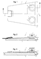
- the pressure jaw 1 forms the one end of a tensioning device, not shown, for floating flooring such as laminates and finished parquet from a plurality of strip-shaped flooring panels to be joined together by means of tongue and groove.
- the angled pressure jaw 1 having a long leg 2 and a short leg 3 with an angled inward again on the short leg 3 and intended for pressing against the carrier material of a floor covering plate 4 has horizontally inwardly projecting edge strip 5 in the long leg 2 has at least two penetrating it in threaded bores 6, spaced-apart distance adjusting screws 7, each with a pressure disc 8 at the end, by means of which the distance between this and the pressure jaw 1 can be adjusted by being supported on the floor covering plate 4.
- edge strip 5 presses essentially directly below the spring 9 of floor covering plates 4 of different floor coverings with different material thickness.
- the tensioning device not shown, with such a pressure jaw can consequently be used for laying laminates as well as for finished parquet, which is thicker in material thickness than the former. Because of this configuration, the wear layer visible after laying on the carrier material of the floor covering plate and the tongue of the tongue and groove connection are never damaged.
- the distance adjusting screws 7 are arranged at the same distance from the short leg 3 of the pressure jaw 1 and on both sides at the same distance from the longitudinal axis of symmetry 10 thereof.
- an area 11 around the thread 6 for each of the distance adjusting screws 7 is curved upward, so that the pressure plate 8 of the distance adjusting screw 7 can be placed underneath and the pressure jaw can rest as flat as possible on the floor covering plate 4.
Landscapes
- Engineering & Computer Science (AREA)
- Architecture (AREA)
- Civil Engineering (AREA)
- Structural Engineering (AREA)
- Floor Finish (AREA)
Abstract
Description
Die einen langen Schenkel 2 und einen kurzen Schenkel 3 aufweisende, abgewinkelte Druckbacke1 mit einer am kurzen Schenkel 3 nochmals abgewinkelten und zum Andrücken gegen das Trägermaterial einer Bodenbelagsplatte 4 bestimmten horizontal einwärts vorspringenden Randleiste 5 weist im langen Schenkel 2 mindestens zwei diesen in Gewindebohrungen 6 durchsetzende, im Abstand voneinander angeordnete Distanzeinstellschrauben 7 mit je einer Andrückscheibe 8 am Ende auf, mittels der durch Abstützen auf der Bodenbelagsplatte 4 der Abstand zwischen dieser und der Druckbacke 1 einstelllbar ist. Damit wird erreicht, dass die Randleiste 5 jeweils im wesentlichen direkt unterhalb der Feder 9 von in der Materialstärke unterschiedlichen Bodenbelagsplatten 4 verschiedener Bodenbeläge andrückt. Die nichht näher dargestellte Spannvorrichtung mit einer solchen Druckbacke kann infolgedessen für das Verlegen von Laminaten wie auch für Fertigparkett verwendet werden, welches gegenüber ersterem in der Materialstärke dicker ist.
Aufgrund dieser Ausgestaltung wird die nach der Verlegung sichtbare Nutzschicht auf dem Trägermaterial der Bodenbelagsplatte wie auch die Feder der Nut-Feder-Verbindung nie beschädigt.
Die Distanzeinstellschrauben 7 sind im gleichen Abstand vom kurzen Schenkel 3 der Druckbacke 1 und beidseits im gleichen Abstand von deren Längssymmetrieachse 10 angeordnet.
Im langen Schenkel 2 der Druckbacke 1 ist ein Bereich 11 um das Gewinde 6 für jede der Distanzeinstellschrauben 7 nach oben gewölbt ausgebildet, damit die Andrückscheibe 8 der Distanzeinstellschraube 7 darunter Platz findet und die Druckbacke möglichst flach auf der Bodenbelagsplatte 4 aufliegen kann.
Claims (3)
- Druckbacke für eine Spannvorrichtung für schwimmend zu verlegenden Bodenbelag wie Laminate und Fertigparkett aus mehreren parallel mittels Nut und Feder ineinander zu fügender streifenförmiger Bodenbelagsplatten, dadurch gekennzeichnet, dass die einen langen und einen kurzen Schenkel (2,3) aufweisende, abgewinkelte Druckbacke (1) mit einer am kurzen Schenkel (3) nochmals abgewinkelten und zum Andrücken gegen das Trägermaterial einer Bodenbelagsplatte (4) bestimmten horizontal einwärts vorspringenden Randleiste (5) im langen Schenkel (2) mindestens zwei diesen in Gewindebohrungen (6) durchsetzende, im Abstand voneinander angeordnete Distanzeinstellschrauben (7) aufweist, mittels der durch Abstützen auf der Bodenbelagsplatte (4) der Abstand zwischen dieser und der Druckbacke (1) einstelllbar ist, zwecks Andrücken der Randleiste (5) im wesentlichen direkt unterhalb der Feder (9) von in der Materialstärke unterschiedlichen Bodenbelagsplatten (4) verschiedener Bodenbeläge.
- Druckbacke nach Anspruch 1, dadurch gekennzeichnet, dass die Distanzeinstellschrauben (7) im gleichen Abstand vom kurzen Schenkel (3) der Druckbacke (1) und von deren Längssymmetrieachse (10) angeordnet sind.
- Druckbacke nach Anspruch 1, dadurch gekennzeichnet, dass jede Distanzeinstellschraube (7) am unteren Ende eine Andrückscheibe (8) trägt und im langen Schenkel (2) der Druckbacke (1) je ein Bereich (11) um das Gewinde (6) für jede der Distanzeinstellschrauben (7) nach oben gewölbt ausgebildet, zwecks Bildung von Freiraum für die Andrückscheibe (8).
Applications Claiming Priority (2)
| Application Number | Priority Date | Filing Date | Title |
|---|---|---|---|
| CH12/97 | 1997-01-06 | ||
| CH00012/97A CH691866A5 (de) | 1997-01-06 | 1997-01-06 | Druckbacke für eine Spannvorrichtung für schwimmend zu verlegenden Bodenbelag. |
Publications (2)
| Publication Number | Publication Date |
|---|---|
| EP0852277A2 true EP0852277A2 (de) | 1998-07-08 |
| EP0852277A3 EP0852277A3 (de) | 1998-09-30 |
Family
ID=4177409
Family Applications (1)
| Application Number | Title | Priority Date | Filing Date |
|---|---|---|---|
| EP98100098A Withdrawn EP0852277A3 (de) | 1997-01-06 | 1998-01-07 | Druckbacke für eine Spannvorrichtung |
Country Status (3)
| Country | Link |
|---|---|
| US (1) | US5946785A (de) |
| EP (1) | EP0852277A3 (de) |
| CH (1) | CH691866A5 (de) |
Families Citing this family (6)
| Publication number | Priority date | Publication date | Assignee | Title |
|---|---|---|---|---|
| US6370836B1 (en) | 2000-08-24 | 2002-04-16 | Dalen Eugene Gunn | Floor board compression apparatus |
| USD515409S1 (en) | 2003-03-12 | 2006-02-21 | Pelco | Cable locking clip |
| USD540265S1 (en) * | 2003-08-22 | 2007-04-10 | Wah Lai | Electrical bus bar stab |
| US20070022845A1 (en) * | 2005-06-22 | 2007-02-01 | Andre Lee-Rodrigues | Heavy duty pull bar |
| US7886785B2 (en) * | 2007-02-15 | 2011-02-15 | Julius Young | Machine and method for installing curved hardwood flooring |
| US11142918B2 (en) * | 2019-02-28 | 2021-10-12 | Ayad S Alkhafaji | Pull bar for click-and-lock flooring systems |
Family Cites Families (8)
| Publication number | Priority date | Publication date | Assignee | Title |
|---|---|---|---|---|
| US2291020A (en) * | 1940-10-26 | 1942-07-28 | Ray E Blomstrom | Siding clamp |
| US2823011A (en) * | 1955-01-10 | 1958-02-11 | Francis A Jones | Siding tool |
| US4280683A (en) * | 1979-07-23 | 1981-07-28 | Dana Corporation | Utility puller |
| US4691907A (en) * | 1985-03-06 | 1987-09-08 | Yang Tai Her | C-clamp structure |
| US4620691A (en) * | 1985-05-16 | 1986-11-04 | Waters Jr Lloyd E | Board straightening device |
| US5297482A (en) * | 1993-04-29 | 1994-03-29 | Cleveland Robert K | Rail threader |
| DE29507795U1 (de) * | 1995-05-11 | 1995-10-12 | Bessey & Sohn GmbH & Co, 74321 Bietigheim-Bissingen | Parkett-Verlegehilfe |
| EP0808964A3 (de) * | 1996-05-20 | 1998-03-25 | Profloor Technology GmbH | Spannvorrichtung für schwimmend zu verlegenden Bodenbelag |
-
1997
- 1997-01-06 CH CH00012/97A patent/CH691866A5/de not_active IP Right Cessation
- 1997-12-24 US US08/997,976 patent/US5946785A/en not_active Expired - Fee Related
-
1998
- 1998-01-07 EP EP98100098A patent/EP0852277A3/de not_active Withdrawn
Also Published As
| Publication number | Publication date |
|---|---|
| EP0852277A3 (de) | 1998-09-30 |
| CH691866A5 (de) | 2001-11-15 |
| US5946785A (en) | 1999-09-07 |
Similar Documents
| Publication | Publication Date | Title |
|---|---|---|
| DE69433415T2 (de) | Methode zum Verlegen und mechanischen Verbinden von Fussbodenplatten und eine Methode zur Herstellung eines Fussbodens | |
| DE2221761C3 (de) | Schwingboden | |
| DE3523357C2 (de) | ||
| EP0808964A2 (de) | Spannvorrichtung für schwimmend zu verlegenden Bodenbelag | |
| DE60126633T2 (de) | Vorgefertigtes deckenstrukturelement und verfahren zur herstellung solcher elemente | |
| EP0852277A2 (de) | Druckbacke für eine Spannvorrichtung | |
| DE1759722A1 (de) | Versiegelte Parkettplatte und Verfahren zu ihrer Herstellung | |
| DE102013014565A1 (de) | Verlegehilfe zum Fliesen | |
| WO1989002017A1 (fr) | Support d'un plancher a surface elastique pour stades | |
| EP3839370A1 (de) | Vorrichtung zum befestigen von solarpaneelen | |
| DE4404310C2 (de) | Spannwerkzeug | |
| EP0033904B1 (de) | Metallklammer für Wand- und Deckenverkleidungen | |
| DE19743807C2 (de) | Kurvenelement für eine Skateanlage (Bowl) | |
| DE69231365T2 (de) | Befestigungssystem für nebeneinander und parallel gesetzte latten | |
| EP1589160A2 (de) | Paneel für ein Zweischichtparkett | |
| EP0859103B1 (de) | Druckbacke für eine Spannvorrichtung | |
| DE68901949T2 (de) | Gebaeudeaussenmauerverkleidung. | |
| DE2555767C2 (de) | Verwendung eines Gartenbausteins | |
| DE3400344C2 (de) | ||
| CH713105A2 (de) | Modulträgermontagesystem für Substrat. | |
| DE29821957U1 (de) | Spannvorrichtung für schwimmend zu verlegenden Bodenbelag | |
| DE3602514A1 (de) | Schindelelement und verfahren zum verschindeln | |
| DE1509248C (de) | Mit einem Unterboden durch Kleben verbindbare mehrschichtige Parkettverlege einheit | |
| DE1509248A1 (de) | Mosaikparkettplatte | |
| EP2025829A2 (de) | Fussbodenbelag |
Legal Events
| Date | Code | Title | Description |
|---|---|---|---|
| PUAI | Public reference made under article 153(3) epc to a published international application that has entered the european phase |
Free format text: ORIGINAL CODE: 0009012 |
|
| AK | Designated contracting states |
Kind code of ref document: A2 Designated state(s): CH DE FR GB LI NL |
|
| AX | Request for extension of the european patent |
Free format text: AL;LT;LV;MK;RO;SI |
|
| PUAL | Search report despatched |
Free format text: ORIGINAL CODE: 0009013 |
|
| AK | Designated contracting states |
Kind code of ref document: A3 Designated state(s): AT BE CH DE DK ES FI FR GB GR IE IT LI LU MC NL PT SE |
|
| AX | Request for extension of the european patent |
Free format text: AL;LT;LV;MK;RO;SI |
|
| 17P | Request for examination filed |
Effective date: 19990324 |
|
| AKX | Designation fees paid |
Free format text: CH DE FR GB LI NL |
|
| RAP3 | Party data changed (applicant data changed or rights of an application transferred) |
Owner name: PROFLOOR TECHNOLOGY GMBH |
|
| STAA | Information on the status of an ep patent application or granted ep patent |
Free format text: STATUS: THE APPLICATION IS DEEMED TO BE WITHDRAWN |
|
| 18D | Application deemed to be withdrawn |
Effective date: 20020801 |