EP0852306B1 - Regelbarer, hydraulischer Getriebemotor - Google Patents
Regelbarer, hydraulischer Getriebemotor Download PDFInfo
- Publication number
- EP0852306B1 EP0852306B1 EP97403145A EP97403145A EP0852306B1 EP 0852306 B1 EP0852306 B1 EP 0852306B1 EP 97403145 A EP97403145 A EP 97403145A EP 97403145 A EP97403145 A EP 97403145A EP 0852306 B1 EP0852306 B1 EP 0852306B1
- Authority
- EP
- European Patent Office
- Prior art keywords
- return
- parallel
- satellites
- points
- connection
- Prior art date
- Legal status (The legal status is an assumption and is not a legal conclusion. Google has not performed a legal analysis and makes no representation as to the accuracy of the status listed.)
- Expired - Lifetime
Links
- 239000012530 fluid Substances 0.000 claims description 30
- 230000001105 regulatory effect Effects 0.000 claims description 8
- 230000004888 barrier function Effects 0.000 description 3
- 238000010586 diagram Methods 0.000 description 3
- 239000007788 liquid Substances 0.000 description 3
- 230000002441 reversible effect Effects 0.000 description 3
- 230000001276 controlling effect Effects 0.000 description 2
- 238000006073 displacement reaction Methods 0.000 description 2
- 238000005461 lubrication Methods 0.000 description 2
- XLYOFNOQVPJJNP-UHFFFAOYSA-N water Substances O XLYOFNOQVPJJNP-UHFFFAOYSA-N 0.000 description 2
- 240000008042 Zea mays Species 0.000 description 1
- 238000002485 combustion reaction Methods 0.000 description 1
- 238000010276 construction Methods 0.000 description 1
- 230000037213 diet Effects 0.000 description 1
- 235000005911 diet Nutrition 0.000 description 1
- 230000000694 effects Effects 0.000 description 1
- 239000003607 modifier Substances 0.000 description 1
- 238000000926 separation method Methods 0.000 description 1
Images


Classifications
-
- F—MECHANICAL ENGINEERING; LIGHTING; HEATING; WEAPONS; BLASTING
- F04—POSITIVE - DISPLACEMENT MACHINES FOR LIQUIDS; PUMPS FOR LIQUIDS OR ELASTIC FLUIDS
- F04C—ROTARY-PISTON, OR OSCILLATING-PISTON, POSITIVE-DISPLACEMENT MACHINES FOR LIQUIDS; ROTARY-PISTON, OR OSCILLATING-PISTON, POSITIVE-DISPLACEMENT PUMPS
- F04C14/00—Control of, monitoring of, or safety arrangements for, machines, pumps or pumping installations
- F04C14/06—Control of, monitoring of, or safety arrangements for, machines, pumps or pumping installations specially adapted for stopping, starting, idling or no-load operation
-
- F—MECHANICAL ENGINEERING; LIGHTING; HEATING; WEAPONS; BLASTING
- F04—POSITIVE - DISPLACEMENT MACHINES FOR LIQUIDS; PUMPS FOR LIQUIDS OR ELASTIC FLUIDS
- F04C—ROTARY-PISTON, OR OSCILLATING-PISTON, POSITIVE-DISPLACEMENT MACHINES FOR LIQUIDS; ROTARY-PISTON, OR OSCILLATING-PISTON, POSITIVE-DISPLACEMENT PUMPS
- F04C2/00—Rotary-piston machines or pumps
- F04C2/08—Rotary-piston machines or pumps of intermeshing-engagement type, i.e. with engagement of co-operating members similar to that of toothed gearing
- F04C2/12—Rotary-piston machines or pumps of intermeshing-engagement type, i.e. with engagement of co-operating members similar to that of toothed gearing of other than internal-axis type
- F04C2/14—Rotary-piston machines or pumps of intermeshing-engagement type, i.e. with engagement of co-operating members similar to that of toothed gearing of other than internal-axis type with toothed rotary pistons
-
- F—MECHANICAL ENGINEERING; LIGHTING; HEATING; WEAPONS; BLASTING
- F16—ENGINEERING ELEMENTS AND UNITS; GENERAL MEASURES FOR PRODUCING AND MAINTAINING EFFECTIVE FUNCTIONING OF MACHINES OR INSTALLATIONS; THERMAL INSULATION IN GENERAL
- F16H—GEARING
- F16H39/00—Rotary fluid gearing using pumps and motors of the volumetric type, i.e. passing a predetermined volume of fluid per revolution
- F16H39/02—Rotary fluid gearing using pumps and motors of the volumetric type, i.e. passing a predetermined volume of fluid per revolution with liquid motors at a distance from liquid pumps
Definitions
- the present invention relates to a motor-variator hydraulic receiving a working fluid and providing a couple.
- hydraulic motors such as "Poclain” type motors or “Hydroland”, composed of a rotor forming cylinders in which move pistons controlling a crankshaft, like an internal combustion engine mounted in a star.
- the motor-variator can be seriously damaged when reversing motion rotation, in particular by a phenomenon of "water hammer".
- the present invention relates to a hydraulic gear motor likely to provide variable output torque, as well as variable operating speeds.
- the motor-drive according to the invention is of a extremely simple construction; it has a rotation safely reversible and provides torque variable by level.
- connection of the different power supplies and back either totally in parallel or totally in series, either in intermediate combinations, allows a large number of output torques while allowing the pump supplying the hydraulic circuit to operate at regular speed and the regulating device avoids serious damage to the motor-drive in the event of reversal of the movement.
- a gear ratio of 1/4 is obtained, with a planetary of 18 teeth, three satellites of 9 teeth and a crown of 36 teeth.
- the satellites have radial channels connecting the bottom of a tooth to bearing of said satellite in order to achieve balancing hydrodynamics of said bearings.
- Figure 1 is a diagram of a motor variator hydraulic gear, showing the principle of operation of this device.
- This hydraulic motor-variator consists of a planetary P associated with two satellites Si, Si + 1 and a crown C; these different elements in the form of cogwheels mesh with each other.
- This intermediate segment forms paths circulation of working fluid by its respective sides, and each time with the planetary P, the satellites Si, Si + 1 and the crown C.
- Each intermediate segment Zi must present curvilinear sides which perfectly fit the outline of the different gears which cooperate with these curvilinear sides. This is necessary for controlling leaks.
- the fluid motor must indeed flow between the teeth of the gears but must not escape from it.
- satellites should rotate as fast as possible so that the working fluid is transported quickly through traffic routes, without having time to escape outside.
- the speed of rotation is therefore also a parameter to consider.
- Each Zi intermediate segment also includes engine fluid inlets and outlets, schematically at each of its four peaks.
- the arrival Ai is at the junction the Si satellite and the C crown; the return Ri is at the junction of satellite Si and planetary P.
- arrivals Ai, ⁇ i + 1 and the returns Ri, ⁇ i + 1 are interchangeable since they depend on the direction of circulation of the working fluid.
- Arrivals define a direction of relative rotation of the planetary, satellites and of the crown.
- An inversion of the direction of circulation of the fluid engine implies that the arrival of the fluid becomes the return and Conversely ; this reverses the direction of rotation of the output of the motor drive.
- the planetary P, the satellites Si, Si + 1 and the crown C are toothed devices which mesh with each other with the others.
- the gears are cut so that their meshing zones, at the intersection with straight lines OXi, OXi + 1 passing through the centers of the different gears P, Si, Si + 1, C, constitute a barrier practically fluid tight.
- the outer surface of the teeth of the gears is preferably grooved according to a particular profile in order to distribute the fluid.
- junction points constitute practically liquid-tight barriers.
- the system between the two lines of axis OXi, OXi + 1 above passing on the one hand by the center of the planetary P and the center of the satellite Si or the center of the satellite Si + 1, constitutes a closed system; it means that, insofar as the working fluid is a liquid, the flow entering this system is equal to the flow outgoing, the liquid being incompressible.
- satellites Si and Si + 1 are gears identical, i.e. having the same number of teeth and the same diameter.
- the driving fluid of the inlet Ai is distributed between a flow Fi, 1 causing the satellite Si in the direction of the arrow and flowing towards the return Ri and a flow Fi, 2 driving crown C in the direction of return ⁇ i + 1.
- the inlet Ai + 1 provides a flow of liquid ⁇ i + 1 driving the satellite Si + 1 towards the exit ⁇ i + 1 and a flow ⁇ i + 1.2 causing the planetary P in return direction Ri.
- the flow rates Fi, 2 and ⁇ i + 1.2 are directly related to the number of teeth in crown C and the planetary P between the axes OXi and OXi + 1.
- the relative rotation speed of the planetary P and crown C is inversely proportional to their diameter since the diameter is proportional itself to the number of teeth carried by these three gears.
- a suitable mechanical means allows keying either the crown or the sun gear on the output shaft of the system.
- a preferred gear ratio is 1/4, with three satellites each having 9 teeth, a planetary of 18 teeth and a crown of 36 teeth. This report authorizes a significant starting torque, compatible with a number of teeth of satellites easily machinable.
- the gear ratio also depends on diet of arrivals Ai, ⁇ i depending on whether this feeding is done in parallel or in series.
- Figure 2 shows a hydraulic motor-drive with three satellites Si, S2, S3.
- the different inputs and outputs A1, R1, ⁇ 1, ⁇ 1, A2 ... have been represented on the lines which arrive directly at the entrances and exits in the sectors Z1, Z2, Z3.
- the separation axes OX1, OX2, OX3 have also been represented.
- variable speed drive is powered in parallel, i.e. the power supplies A1, A2, A3, ⁇ 1, ⁇ 2, ⁇ 3 are connected in parallel.
- the common power supply has the reference A100 and the return common reference R100.
- FIG 3A shows schematically the connection in parallel on either side of a satellite for example the S1 satellite.
- Power supply A is connected to the inlet ⁇ 2 which drives the satellite Si in the direction of the arrow indicated; the flow arrives at the return ⁇ 2 of the satellite Si.
- This return ⁇ 2 is connected to exit R.
- Another branch of power supply A is connected to the inlet A1 and the corresponding return R1 is connected to the general return R.
- FIGS 3B, 4B show the connection for switch from parallel to serial mode.
- Arrival A1 and return R1 correspond to a "engine-satellite" shown schematically under the reference M1; the arrival A2 and the return R2 correspond to the "engine-satellite” schematically represented by the reference M2.
- the supply line A is connected by a branch line at the two lines A1, A2 supplying respectively the "motor satellites" M1, M2 whose returns R1, R2 are linked to the general return R.
- connection of the A2 inlet is cut off power supply A; the same applies to the connection between the return R1 and general return R.
- connection C1 is open.
- the working fluid therefore flows in the direction indicated by the arrows passing in series through the "motor satellites" M1, M2, i.e. following the paths A1 M1, R1, C1, A2, M2, R2, R.
- Figures 5A, 5B, 5C, 5D schematically show how to connect four "motor satellites" M1, M2, M3, M4 to switch from a full parallel connection to a complete serial connection.
- the Mi "motor satellites” represented in these different figures correspond to the “motor satellites” M1, M2, etc ... described above, i.e. corresponding to each times at an inlet and outlet of working fluid.
- FIGS. 5A and 5D represent intermediate steps between FIGS. 5A and 5D, i.e. intermediate torques and speeds intermediate.
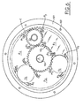
- Figures 6 and 7 show an embodiment in plan view and in sectional view of a single-speed motor-variator planetary gear P, three satellite gears S1, S2, S3 and a gear in crown C.
- the satellites are separated as before by sectors Z1, Z2, Z3.
- Figure 7 is a sectional view of the device Figure 6. This figure shows the planetary P carried by the output axis 100, meshing with the satellite S1.
- the S3 satellite was not represented but only the cavity who receives it. This cavity is delimited by the two sectors Z1, Z3 and the crown C as well as the planetary P.
- the crown C is housed in the casing 101 provided a mounting flange 102.
- the assembly thus described is closed by a cover 103 with a general input nozzle A and a return nozzle R; the various distribution channels (not referenced) emerge in the lights like those (A3, R3) represented for example.
- These distribution channels will have a cross-section adapted to the engine displacement, i.e. to the torque and / or the engine operating speed. More sections important will be chosen when torques and speeds higher will have to be developed. Indeed the couple is proportional to the pressure-surface ratio. The surface being the exposed surface which depends on the number of teeth of the satellite, their geometry.
- Figure 7 also shows the different bearings 104, 105 and the key 106 of the axis 100.
- the crown C meshes with axis 100 by grooves not referenced.
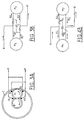
- FIGS 8A, 8B show a device regulator 200 for regularizing operation during an inversion of movement.
- the motion reverser 300 is shown as a two-drawer dispenser positions connecting inlet A and return R to the conduits (L1, L2) or (L2, L1).
- the device 200 is shown in connection with three "motor satellites" M1, M2, M3 like those described above. These "motor satellites" M1, M2, M3 are linked respectively to line L1, via lines L11, L21, L31 and to line L2, via lines L12, L22, L32.
- the connection to line L2 is made via a dispenser 201 with drawer 202.
- Drawer 202 which has areas P1, P2, P3, is subjected to the action of a return spring 203 and of the fluid pressure in a chamber 204.
- the drawer 202 is normally positioned by through its rod 205. It can nevertheless retract relative to the rod 205 by compressing the spring 203. This retraction movement occurs when the pressure in the room 204 quickly becomes too important during a reverse movement of the gear motor.
- the pipe L1 corresponds to inlet A and line L2 on return R.
- each satellite has a level lubricated by extending connecting channels radially from the bearing to the hollow of a satellite tooth.
- Preferably three channels are provided, at 120 ° from each other. An oil film is thus created all around the bearing. This allows a regularly distributed lubrication, with a hydrodynamic balancing.
- the outer surfaces of the teeth can be grooved according to a particular profile. This increases by better lubrication the life of these gears.
Landscapes
- Engineering & Computer Science (AREA)
- General Engineering & Computer Science (AREA)
- Mechanical Engineering (AREA)
- Hydraulic Motors (AREA)
- Retarders (AREA)
- Structure Of Transmissions (AREA)
- General Details Of Gearings (AREA)
Claims (7)
- Hydraulischer Motorvariator mit Getriebesatz, dem Antriebsfluid zugeführt wird und der ein Kraftmoment und eine Geschwindigkeit ergibt, die variabel sind, mit einer epizykloidalen Anordnung, umfassend:ein Zentralrad (P),wenigstens zwei Satellitenräder (Si, Si+1),einen Kranz (C),einen Zwischenbereich (Zi) in Form eines Kurvenlinientrapezes, der das Volumen, zwischen den gegenüberliegenden Seiten des Zentralrades (P), der beiden benachbarten Satellitenräder (Si, Si+1) und dem Kranz (C) unter Annahme von deren Kontur einnimmt und indem mit ihnen Zirkulationswege der Motorflüssigkeit definiert werden,Verbindungen (J(P, Si) J(Si, C) J(Si+1, C) J(P, Si+1)), zwischen dem Zentralrad (P) und den benachbarten Satellitenrädern (Si, Si+1) und dem Kranz (C), die gegen das Antriebsfluid abdichtend ausgebildet sind,die beiden Eingänge (Ai, αi+1) und die beiden Rückläufe (Ri, ρi+1) des Antriebsfluids, welche in dem Bereich (Zi) in der Nähe der Verbindungen (J(P, Si), J(Si, C), J(Si+1, C), J(P, Si+1)) vorgesehen sind, wobei die Eingänge (Ai, αi+1) und die Rückläufe (Ri, ρi+1)jeweils auf dem Niveau der beiden gegenüberliegenden Spitzen des durch den Bereich (Zi) gebildeten Kurvenlinientrapezes angeordnet sind,eine Zufuhr (Eingang A, Rücklauf R), die von den Eingängen (Ai, αi+1) und den Rückläufen (Ri, ρi+1) gesteuert wird, welche mit dem hydraulischen Kreislauf verbunden ist, dadurch gekennzeichnet, dass diese Zufuhr es ermöglicht, die Eingänge (Ai, αi+1) und die Rückläufe (Ri, ρi+1) parallel oder in Reihe oder gemäß einer Zwischenkombination zwischen einem Anschluss vollständig in Reihe und einem vollständig parallelen Anschluss anzuordnen, um das am Ausgang gelieferte Kraftmoment zu modifizieren und dadurch, dass die gesteuerte Zufuhr eine Steuervorrichtung (200) umfasst, die im Fall einer Bewegungsumkehr automatisch den Anschluss der Motoren (Mi) parallel unabhängig von deren Anschlussstellung vor der Bewegungsumkehr automatisch steuert
- Motorvariator nach Anspruch 1, dadurch gekennzeichnet, dass die gesteuerte Zufuhr einen Bewegungsinverter (300), insbesondere in Form eines Schiebeverteilers mit zwei Positionen hat.
- Motorvariator nach Anspruch 1, dadurch gekennzeichnet, dass die Steuervorrichtung (200) einen Schieber (202) mit Öffnungsbereichen (P1, P2, P3) unterschiedlicher Längen hat, wobei dieser Schieber durch einen Steuerschieber (205), positioniert wird, dessen nicht mit der Steuerung verbundenes Ende dem in der Kammer (204) der Steuervorrichtung herrschenden Druck unterliegt, wobei die Kammer (204) mit einer der Leitungen (L1, L2) des Inverters (300) verbunden ist und das andere Ende des Verteilers durch eine Feder (203) vorgeschoben wird, die sich derart gegen das Steuerorgan (205) abstützt, dass der zum Zeitpunkt des Umkehr des Fluiddurchgangs durch den Inverter (300) in der Kammer (204) erzeugte Druckstoß die Bewegung des Schiebers (202) gegen die von der Feder (203) erzeugte Kraft steuert, die sich gegen das andere Ende abstützt, um automatisch alle 'Sattelitenmotoren' (M1, M2, M3) unabhängig vom Anschlussschema dieser 'Sattelitenmotoren' vor der Umkehr parallel zu stellen.
- Motorvariator nach einem der vorhergehenden Ansprüche, dadurch gekennzeichnet, dass er vorzugsweise ein Untersetzungsverhältnis von ¼ aufweist.
- Motorvariator nach Anspruch 4, dadurch gekennzeichnet, dass er 3 Sattelitenräder mit jeweils 9 Zähnen, ein Zentralrad mit 18 Zähnen und einen Kranz mit 36 Zähnen umfasst.
- Motorvariator nach einem der vorhergehenden Ansprüche, dadurch gekennzeichnet, dass die Sattelitenräder radiale Kanäle aufweisen, die den tiefsten Teil eines Zahnes mit dem Lager des Sattelitenrades verbinden, um ein hydrodynamisches Gleichgewicht dieser Lager zu verwirklichen.
- Motorvariator nach Anspruch 6, dadurch gekennzeichnet, dass diese radialen Kanäle mit 120° voneinander winkelbeabstandet sind.
Applications Claiming Priority (2)
| Application Number | Priority Date | Filing Date | Title |
|---|---|---|---|
| FR9700028 | 1997-01-03 | ||
| FR9700028A FR2758172B1 (fr) | 1997-01-03 | 1997-01-03 | Moto-variateur hydraulique a engrenages, alimente en fluide moteur et fournissant un couple variable |
Publications (2)
| Publication Number | Publication Date |
|---|---|
| EP0852306A1 EP0852306A1 (de) | 1998-07-08 |
| EP0852306B1 true EP0852306B1 (de) | 2002-03-27 |
Family
ID=9502369
Family Applications (1)
| Application Number | Title | Priority Date | Filing Date |
|---|---|---|---|
| EP97403145A Expired - Lifetime EP0852306B1 (de) | 1997-01-03 | 1997-12-23 | Regelbarer, hydraulischer Getriebemotor |
Country Status (6)
| Country | Link |
|---|---|
| US (1) | US6030196A (de) |
| EP (1) | EP0852306B1 (de) |
| CA (1) | CA2224483C (de) |
| DE (1) | DE69711356T2 (de) |
| ES (1) | ES2174203T3 (de) |
| FR (1) | FR2758172B1 (de) |
Families Citing this family (7)
| Publication number | Priority date | Publication date | Assignee | Title |
|---|---|---|---|---|
| US8596165B2 (en) * | 2006-06-09 | 2013-12-03 | Parker-Hannifin Corporation | Multiple gear motor drive |
| US7802494B2 (en) | 2006-11-13 | 2010-09-28 | Batistic Robert N | Electrically driven propulsion system |
| US20090088280A1 (en) * | 2007-09-28 | 2009-04-02 | Kendall Alden Warren | Variable delivery gear pump |
| US20100038192A1 (en) * | 2008-08-15 | 2010-02-18 | Culbertson Michael O | Floating yaw brake for wind turbine |
| US20100038191A1 (en) * | 2008-08-15 | 2010-02-18 | Culbertson Michael O | Modular actuator for wind turbine brake |
| DE102010056106B4 (de) * | 2010-12-23 | 2012-07-19 | Magna Powertrain Ag & Co. Kg | Getriebeeinheit |
| WO2016166746A1 (en) * | 2015-04-12 | 2016-10-20 | Concept & Design Ltd. | A hydrostatic transmission and method of operation |
Family Cites Families (6)
| Publication number | Priority date | Publication date | Assignee | Title |
|---|---|---|---|---|
| US3298284A (en) * | 1964-09-11 | 1967-01-17 | Rockwell Mfg Co | Servo operated reversing tool |
| US3506081A (en) * | 1967-12-29 | 1970-04-14 | Houdaille Industries Inc | Wheel driving hydraulic motor circuits |
| AT311179B (de) * | 1970-04-27 | 1973-11-12 | Deckel Ag Friedrich | Zahnradmotor bzw. -pumpe |
| US3833317A (en) * | 1971-03-04 | 1974-09-03 | R Rumsey | Rotary gear motor/pump having hydrostatic bearing means |
| US3688648A (en) * | 1971-05-03 | 1972-09-05 | Michael A D Amato Jr | Automatic control valve system for hydraulic motor |
| US4347700A (en) * | 1980-02-21 | 1982-09-07 | Transcience Associates, Inc. | Direct-drive hydraulic pump-motor |
-
1997
- 1997-01-03 FR FR9700028A patent/FR2758172B1/fr not_active Expired - Fee Related
- 1997-12-23 DE DE69711356T patent/DE69711356T2/de not_active Expired - Fee Related
- 1997-12-23 EP EP97403145A patent/EP0852306B1/de not_active Expired - Lifetime
- 1997-12-23 ES ES97403145T patent/ES2174203T3/es not_active Expired - Lifetime
-
1998
- 1998-01-02 CA CA002224483A patent/CA2224483C/fr not_active Expired - Fee Related
- 1998-01-05 US US09/003,467 patent/US6030196A/en not_active Expired - Fee Related
Also Published As
| Publication number | Publication date |
|---|---|
| DE69711356T2 (de) | 2002-07-18 |
| FR2758172A1 (fr) | 1998-07-10 |
| DE69711356D1 (de) | 2002-05-02 |
| EP0852306A1 (de) | 1998-07-08 |
| FR2758172B1 (fr) | 1999-02-26 |
| CA2224483A1 (fr) | 1998-07-03 |
| CA2224483C (fr) | 2006-11-14 |
| ES2174203T3 (es) | 2002-11-01 |
| US6030196A (en) | 2000-02-29 |
Similar Documents
| Publication | Publication Date | Title |
|---|---|---|
| FR2508973A1 (fr) | Prise de couple auxiliaire sur moteur thermique a explosion ou a combustion interne | |
| EP1208317A1 (de) | Kraftfahrzeugantriebseinheit mit stufenlosem getriebe | |
| FR2648205A1 (fr) | Transmission a poulies expansibles, en particulier pour vehicules automobiles | |
| EP3982009B1 (de) | Mechanisches reduktionsgetriebe für turbotriebwerk eines luftfahrzeugs | |
| EP0852306B1 (de) | Regelbarer, hydraulischer Getriebemotor | |
| FR2642017A1 (fr) | Structure de commande de vitesse notamment pour un tracteur agricole | |
| EP0969205A1 (de) | Hydromotor in Kompaktbauweise | |
| EP0066507B1 (de) | Hydraulischer Rotationsverteiler für eine hydraulische Antriebseinrichtung | |
| EP3201492A1 (de) | Untersetzungsgetriebe mit zwei zwischenliegenden getriebesträngen | |
| EP3879133A1 (de) | Doppelnasskupplung | |
| FR2458419A1 (fr) | Perfectionnement a une transmission automatique a essieu transversal | |
| EP3004692A1 (de) | Getriebe mit schmierung eines synchrongetriebes | |
| WO2014048838A1 (fr) | Différentiel intégrant un appareil hydraulique | |
| FR2697883A1 (fr) | Ensemble hydromécanique d'entraînement. | |
| EP3807508B1 (de) | Rotierender planetenträger für ein mechanisches untersetzungsgetriebe einer turbomaschine | |
| EP0277861A1 (de) | Hydraulische Schraubenmotoren | |
| FR2760048A1 (fr) | Entrainement hydraulique pour engin de chantier | |
| FR2874061A1 (fr) | Dispositif a diffuseur interne au rotor permettant de transf ormer l'energie hydraulique en un mouvement rotatif | |
| EP3807507B1 (de) | Vorrichtung zur ölverteilung für einen rotierenden planetenträger eines untersetzungsgetriebes einer turbomaschine | |
| FR2910581A1 (fr) | Transmission a fonctionnement continu, a derivation de puissance hydrostatique-mecanique | |
| EP4504592A1 (de) | Vorrichtung zur erzeugung eines fluidstroms mit einer membran | |
| FR2646380A1 (fr) | Dispositif formant groupe moto-propulseur notamment pour vehicule automobile | |
| CA1189388A (fr) | Dispositif hydraulique rotatif convertisseur et repartiteur a multi-cylindrees synchronisees | |
| EP0215705B1 (de) | Hydromechanischer Drehmomentwandler | |
| FR2613804A1 (fr) | Dispositif de transmission hydromecanique de mouvement de rotation |
Legal Events
| Date | Code | Title | Description |
|---|---|---|---|
| PUAI | Public reference made under article 153(3) epc to a published international application that has entered the european phase |
Free format text: ORIGINAL CODE: 0009012 |
|
| AK | Designated contracting states |
Kind code of ref document: A1 Designated state(s): DE ES FR GB IT |
|
| AX | Request for extension of the european patent |
Free format text: AL;LT;LV;MK;RO;SI |
|
| 17P | Request for examination filed |
Effective date: 19990108 |
|
| AKX | Designation fees paid |
Free format text: DE ES FR GB IT |
|
| RBV | Designated contracting states (corrected) |
Designated state(s): DE ES FR GB IT |
|
| 17Q | First examination report despatched |
Effective date: 20000721 |
|
| GRAG | Despatch of communication of intention to grant |
Free format text: ORIGINAL CODE: EPIDOS AGRA |
|
| GRAG | Despatch of communication of intention to grant |
Free format text: ORIGINAL CODE: EPIDOS AGRA |
|
| GRAH | Despatch of communication of intention to grant a patent |
Free format text: ORIGINAL CODE: EPIDOS IGRA |
|
| REG | Reference to a national code |
Ref country code: GB Ref legal event code: IF02 |
|
| GRAH | Despatch of communication of intention to grant a patent |
Free format text: ORIGINAL CODE: EPIDOS IGRA |
|
| GRAA | (expected) grant |
Free format text: ORIGINAL CODE: 0009210 |
|
| AK | Designated contracting states |
Kind code of ref document: B1 Designated state(s): DE ES FR GB IT |
|
| REF | Corresponds to: |
Ref document number: 69711356 Country of ref document: DE Date of ref document: 20020502 |
|
| GBT | Gb: translation of ep patent filed (gb section 77(6)(a)/1977) |
Effective date: 20020416 |
|
| REG | Reference to a national code |
Ref country code: ES Ref legal event code: FG2A Ref document number: 2174203 Country of ref document: ES Kind code of ref document: T3 |
|
| PLBE | No opposition filed within time limit |
Free format text: ORIGINAL CODE: 0009261 |
|
| STAA | Information on the status of an ep patent application or granted ep patent |
Free format text: STATUS: NO OPPOSITION FILED WITHIN TIME LIMIT |
|
| 26N | No opposition filed |
Effective date: 20021230 |
|
| PGFP | Annual fee paid to national office [announced via postgrant information from national office to epo] |
Ref country code: ES Payment date: 20051202 Year of fee payment: 9 |
|
| PGFP | Annual fee paid to national office [announced via postgrant information from national office to epo] |
Ref country code: DE Payment date: 20060103 Year of fee payment: 9 |
|
| PGFP | Annual fee paid to national office [announced via postgrant information from national office to epo] |
Ref country code: GB Payment date: 20061219 Year of fee payment: 10 |
|
| PGFP | Annual fee paid to national office [announced via postgrant information from national office to epo] |
Ref country code: IT Payment date: 20061231 Year of fee payment: 10 |
|
| PG25 | Lapsed in a contracting state [announced via postgrant information from national office to epo] |
Ref country code: DE Free format text: LAPSE BECAUSE OF NON-PAYMENT OF DUE FEES Effective date: 20070703 |
|
| REG | Reference to a national code |
Ref country code: ES Ref legal event code: FD2A Effective date: 20061226 |
|
| PG25 | Lapsed in a contracting state [announced via postgrant information from national office to epo] |
Ref country code: ES Free format text: LAPSE BECAUSE OF NON-PAYMENT OF DUE FEES Effective date: 20061226 |
|
| GBPC | Gb: european patent ceased through non-payment of renewal fee |
Effective date: 20071223 |
|
| PGFP | Annual fee paid to national office [announced via postgrant information from national office to epo] |
Ref country code: FR Payment date: 20061016 Year of fee payment: 10 |
|
| REG | Reference to a national code |
Ref country code: FR Ref legal event code: ST Effective date: 20081020 |
|
| PG25 | Lapsed in a contracting state [announced via postgrant information from national office to epo] |
Ref country code: GB Free format text: LAPSE BECAUSE OF NON-PAYMENT OF DUE FEES Effective date: 20071223 |
|
| PG25 | Lapsed in a contracting state [announced via postgrant information from national office to epo] |
Ref country code: FR Free format text: LAPSE BECAUSE OF NON-PAYMENT OF DUE FEES Effective date: 20071231 |
|
| PG25 | Lapsed in a contracting state [announced via postgrant information from national office to epo] |
Ref country code: IT Free format text: LAPSE BECAUSE OF NON-PAYMENT OF DUE FEES Effective date: 20071223 |