EP0852629B1 - Dispositif servant au nettoyage de metaux apres leur traitement a haute temperature - Google Patents
Dispositif servant au nettoyage de metaux apres leur traitement a haute temperature Download PDFInfo
- Publication number
- EP0852629B1 EP0852629B1 EP96930346A EP96930346A EP0852629B1 EP 0852629 B1 EP0852629 B1 EP 0852629B1 EP 96930346 A EP96930346 A EP 96930346A EP 96930346 A EP96930346 A EP 96930346A EP 0852629 B1 EP0852629 B1 EP 0852629B1
- Authority
- EP
- European Patent Office
- Prior art keywords
- previous
- electrode
- insulating material
- cleaning
- nib
- Prior art date
- Legal status (The legal status is an assumption and is not a legal conclusion. Google has not performed a legal analysis and makes no representation as to the accuracy of the status listed.)
- Expired - Lifetime
Links
- 229910052751 metal Inorganic materials 0.000 title claims abstract description 52
- 239000002184 metal Substances 0.000 title claims abstract description 51
- 238000004140 cleaning Methods 0.000 title claims description 29
- 239000004744 fabric Substances 0.000 claims abstract description 29
- 239000002253 acid Substances 0.000 claims abstract description 26
- 239000004696 Poly ether ether ketone Substances 0.000 claims abstract description 20
- 229920002530 polyetherether ketone Polymers 0.000 claims abstract description 20
- 239000011810 insulating material Substances 0.000 claims description 41
- 150000002739 metals Chemical class 0.000 claims description 18
- 239000000463 material Substances 0.000 claims description 15
- 239000007789 gas Substances 0.000 claims description 10
- 230000009471 action Effects 0.000 claims description 9
- 239000004809 Teflon Substances 0.000 claims description 8
- 229920006362 Teflon® Polymers 0.000 claims description 8
- 229910001220 stainless steel Inorganic materials 0.000 claims description 8
- 239000010935 stainless steel Substances 0.000 claims description 7
- 238000004519 manufacturing process Methods 0.000 claims description 5
- 238000009413 insulation Methods 0.000 claims description 3
- 239000003517 fume Substances 0.000 claims description 2
- 239000007769 metal material Substances 0.000 claims description 2
- 210000003323 beak Anatomy 0.000 description 67
- 239000003929 acidic solution Substances 0.000 description 30
- 239000000243 solution Substances 0.000 description 16
- 239000003365 glass fiber Substances 0.000 description 7
- 239000011248 coating agent Substances 0.000 description 5
- 238000000576 coating method Methods 0.000 description 5
- 239000004020 conductor Substances 0.000 description 5
- NBIIXXVUZAFLBC-UHFFFAOYSA-N Phosphoric acid Chemical compound OP(O)(O)=O NBIIXXVUZAFLBC-UHFFFAOYSA-N 0.000 description 4
- SMWDFEZZVXVKRB-UHFFFAOYSA-N Quinoline Chemical compound N1=CC=CC2=CC=CC=C21 SMWDFEZZVXVKRB-UHFFFAOYSA-N 0.000 description 4
- 230000008901 benefit Effects 0.000 description 3
- KRKNYBCHXYNGOX-UHFFFAOYSA-N citric acid Chemical compound OC(=O)CC(O)(C(O)=O)CC(O)=O KRKNYBCHXYNGOX-UHFFFAOYSA-N 0.000 description 3
- 238000012545 processing Methods 0.000 description 3
- 229910000147 aluminium phosphate Inorganic materials 0.000 description 2
- 238000011161 development Methods 0.000 description 2
- 238000010586 diagram Methods 0.000 description 2
- 238000010438 heat treatment Methods 0.000 description 2
- 230000006872 improvement Effects 0.000 description 2
- 239000007788 liquid Substances 0.000 description 2
- 238000003754 machining Methods 0.000 description 2
- 238000000034 method Methods 0.000 description 2
- 230000003647 oxidation Effects 0.000 description 2
- 238000007254 oxidation reaction Methods 0.000 description 2
- 230000008569 process Effects 0.000 description 2
- XLYOFNOQVPJJNP-UHFFFAOYSA-N water Substances O XLYOFNOQVPJJNP-UHFFFAOYSA-N 0.000 description 2
- 229910000831 Steel Inorganic materials 0.000 description 1
- 150000007513 acids Chemical class 0.000 description 1
- 230000006978 adaptation Effects 0.000 description 1
- JUPQTSLXMOCDHR-UHFFFAOYSA-N benzene-1,4-diol;bis(4-fluorophenyl)methanone Chemical compound OC1=CC=C(O)C=C1.C1=CC(F)=CC=C1C(=O)C1=CC=C(F)C=C1 JUPQTSLXMOCDHR-UHFFFAOYSA-N 0.000 description 1
- 238000002485 combustion reaction Methods 0.000 description 1
- 238000005520 cutting process Methods 0.000 description 1
- 238000013461 design Methods 0.000 description 1
- 238000005553 drilling Methods 0.000 description 1
- 230000000694 effects Effects 0.000 description 1
- 239000013013 elastic material Substances 0.000 description 1
- 238000005516 engineering process Methods 0.000 description 1
- 238000001704 evaporation Methods 0.000 description 1
- 230000008020 evaporation Effects 0.000 description 1
- 238000000605 extraction Methods 0.000 description 1
- 238000007373 indentation Methods 0.000 description 1
- 238000011031 large-scale manufacturing process Methods 0.000 description 1
- 238000012423 maintenance Methods 0.000 description 1
- 238000001556 precipitation Methods 0.000 description 1
- 230000009467 reduction Effects 0.000 description 1
- 230000001105 regulatory effect Effects 0.000 description 1
- 230000000284 resting effect Effects 0.000 description 1
- 238000002791 soaking Methods 0.000 description 1
- 239000010959 steel Substances 0.000 description 1
- 208000024891 symptom Diseases 0.000 description 1
- 238000012360 testing method Methods 0.000 description 1
- 230000000930 thermomechanical effect Effects 0.000 description 1
- 238000009423 ventilation Methods 0.000 description 1
- 238000005406 washing Methods 0.000 description 1
- 238000003466 welding Methods 0.000 description 1
Images

Classifications
-
- C—CHEMISTRY; METALLURGY
- C25—ELECTROLYTIC OR ELECTROPHORETIC PROCESSES; APPARATUS THEREFOR
- C25F—PROCESSES FOR THE ELECTROLYTIC REMOVAL OF MATERIALS FROM OBJECTS; APPARATUS THEREFOR
- C25F7/00—Constructional parts, or assemblies thereof, of cells for electrolytic removal of material from objects; Servicing or operating
Definitions
- the invention relates to: a device for cleaning of metals after their processing at high temperatures, i.e. a device with which the oxidations, Stains or other appearances that are machining high temperatures such as welding and laser or plasma cutting of metals on their surface can be eliminated.
- the current state of the art knows a device which consists of a plug made of glass fiber fabric which is wrapped around the end of a beak-shaped electrode.
- This stopper is impregnated with an acidic solution based on phosphoric acid (81% by weight) and quinoline (0.01% by weight) and water and then placed near the surface to be worked.
- the acidic solution has a very high density, which is also necessary so that when it is applied to vertical surfaces to be treated or to surfaces on the underside, it does not drip down onto the operator or run down the wall.
- it is not very practical for the operator if he has a container with an acid solution and a large amount of glass fiber insulating fabric with which he has to wrap the electrode beak next to him, which makes the work not continuous and therefore not very productive and sometimes is dangerous.
- the current state of the art also knows devices for cleaning metals with low-viscosity acidic solutions - based on citric acid - which is constantly fed to the plug by means of an electric submersible pump installed in the acid container.
- the above-mentioned device has never been used on an industrial scale.
- the electrode through which the current flows and surrounded by the plug heats up, since it is not only a good electrical conductor, but also a good heat conductor: the temperature rise recorded in this way as a result of the heat accumulated by the plug leads to rapid evaporation of the aforementioned acidic solution, so that an undesired combustion of this plug can also occur, which in turn causes a short circuit between the electrode and the surface to be cleaned. Therefore, the plug must be replaced relatively often.
- none of the previously known devices provide protection for the operator from the vapors occurring during cleaning.
- This prior art can be used in several ways can be improved to eliminate the above-mentioned disadvantages and to make the device safer and easier to use to design as well as a longer life to achieve the graft.
- an acid supply circuit in which the high-density and strongly aggressive acid is sucked in by means of a hand pump or in another way from the acid tank, which consists of insulating material or is insulated from the environment.
- a metal beak - hollow or with an axial bore - is provided inside the plug through which the acid is conveyed and which is mounted on the end of the electrode.
- the above-mentioned beak is surrounded by tissue made of insulating material, which is turned over so that two parts are created, and which is fastened or held with a ring made of elastic, insulating or shrinking-hardening material; this elastic or isolating ring can be reused several times after the plug has been replaced from folded fabric.
- the above-mentioned beak can consist of a metal body and a replaceable end made of insulating material, inside of which there is at least one metal body which ends at the end face of the beak and activates the electrolytic action.
- the interchangeable end of the beak made of metal material is coated on the side walls with insulating material, so that there is electrical continuity in the contact area with the beak body and on the non-insulated end face. This end surface is provided with holes through which the acidic solution is passed.
- the above-mentioned insulating coating consists of a Teflon film with a thickness of 0.1 - 0.3 mm for protection against short circuits and 0.6 - 1.2 mm for thermal insulation.
- the material for the beak ie both for the body and for the replaceable metal end, can be selected from high-strength stainless steel.
- the AISI 316 steel grade should preferably be used as the high-strength stainless steel for the replaceable metal end.
- the material for insulating the electrode has been improved; the plug is made of polyether ether ketone fabric (trade name PEEK from Hoechst) and is used to wrap the metal end of the beak-shaped electrode.
- the above-mentioned fabric made of polyether ether ketone can also be used in the form of a felt.
- the above-mentioned fabric made of polyether ether ketone can also be used in the form of a network, which is coated with a felt layer made of any heat-resistant insulating material, this layer being able to be applied subsequently or provided directly during production.
- the above-mentioned fabric made of polyether ether ketone can be coated with a felt layer, whereby this felt can also consist of polyether ether ketone.
- the mentioned layer of felt is applied to the beak on the outside of the fabric layer made of polyether ether ketone.
- the acid is supplied directly by the operator and as often as required; a very aggressive solution can also be used, the time lost for soaking the plug is eliminated and no acid can be lost during transport from the container to the processing point.
- the plug is soaked better with acid and therefore heats up less or wears out less due to thermomechanical stress.
- the beak of the electrode can have a wide variety of shapes, which depend on the particular machining position; if the beak is cone-shaped, the stocking can be changed more quickly.
- the supply of the acidic solution inside the plug prevents acid from spilling or reaching parts that cannot be cleaned.
- the lifespan of the stocking is that the electrode end is made of insulating material or if it is made of metal, because it is coated with a thick layer of insulating material, compared to the short lifespan of a completely metal one existing electrode significantly improved.
- a maximum service life can be achieved by using a double-layer plug, which has a fabric layer on the inside and a felt layer on the outside:
- the inside fabric can be polyether ether ketone.
- the polyetheretherketone fabric can achieve the highest durability values because it has a very high resistance to heating and acids.
- the outer layer of felt made of any suitable material, such as the aforementioned glass fiber, holds the solution at the cleaning point and enables adaptation to the shape of the workpiece, which greatly increases the life of the stocking.
- maximum performance can be achieved in terms of service life, precision and quantity of work.
- the fact that the end of the beak is exchangeable makes it possible to manufacture the body of the beak from ordinary stainless steel, whereas the end can be made from special stainless steel, which is more expensive but wears less quickly. This results in an improvement in the efficiency of the cleaning process.
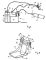
- the image 1 provides an overall view of the acid delivery device and stocking made of insulating material fabric
- Figure 2 is an enlarged view of the beak of the plug wrapped in the stocking.
- Illustration 3 shows the hydraulic diagram of the pump which is the acid one Solution sucks.
- Figure 4 is the hydraulic / pneumatic diagram the pump that blows the air into the acid tank, whereby the acidic solution is applied.
- Figure 5 represents the cut through a beak with a truncated cone Metal insert and sock made from improved insulating material
- Figure 6 is the section VI-VI through the frustoconical insert.
- Figure 7 shows that inventive scheme of suction of gases and vapors, which are characterized by form the heating of the acidic solution, and its precipitation wet process.
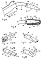
- Figure 8 is a partial outline a pistol with an improved interchangeable beak with plug connection, which can be adapted to the respective Allows working position.
- Figure 9 is the improved one Beak shown with the stocking made of insulating material is wrapped.
- Figure 10 is a back Outline view of the improved beak on which the lines running inside are shown.
- Illustration 11 is an outline view of the front of this Beak.
- Figures 12 and 13 show the views two beaks used for the treatment of difficult to access Jobs are trained.
- Figure 14 is the view a beak with a brush made of insulating material for the treatment of hard to reach places.
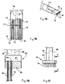
- Illustration 15 is the outline view of the electrode, the end of which is shown in FIG the invention is carried out with insulating material.
- Illustration 16 is the enlarged section through a longitudinal plane the beak of the electrode.
- Figure 17 is the view a beak with a brush made of insulating material Treatment of hard-to-reach areas.
- Figure 18 shows the section F-F through the enlarged Figure 17 limited to two of the filiform tubes.
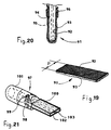
- Illustration 19 is an outline view of a plug from FIG double layer of special material for wrapping the Beak.
- Figure 20 shows the end of the beak, in which the plug is wrapped with the double layer.
- Figure 21 is the outline view of a metal beak with interchangeable end, which is attached to the body with screws is attached and covered with a thick layer of insulation is.
- Figure 1 the electrical Supply device consisting of a transformer 2 for converting mains voltage to low voltage, a selector switch 3 for regulating the output voltage, two terminals 4 for conductors 5 and 6, from which one by means of pliers 9 to the body 7 of the treating surface 8 and the other to the body 10 the electrode, which ends with the beak 11, which in turn is surrounded by the stocking 12 which is clamped by the clamp 13 is held, is connected; at 14 a small pipe for supplying the acidic solution inside or outside the insulating handle 15, the acidic solution using a pump 16 from the tank 17, which contains the acidic solution 18 and is insulated from the rest of the device becomes; at 19 the gas cap with ventilation; with 20, illustration 2, the piece of stocking made of insulating material fabric, with which the beak 11 and the end of the body 10 of the Electrode is wrapped; at 21 on the beak tip bent stocking held by the clamp 13; With 22 a pump that compresses the air in the tank 23 and Generates pressure that causes the acidic solution
- the body of the tapered metal beak that holds the electrode represents; at 72 the end of this beak made of insulating material with a bore 73 for supplying the acidic solution to the stocking that represents the plug and the clarity is not shown for the sake of; with 74 of Head of the screws for attachment to this body, the attached near the end face S: the shaft these screws extend into the corresponding threaded hole 75, Figure 16; at 76 the hole over which the acidic solution is passed into said body; at 77 the contact surfaces between the body 71 and the end 72: due to the sufficient flexibility of the used Material, i.e. glass fiber reinforced Teflon, none Seals used. If there are any leaks, these are characterized by the stocking, not shown Isoliermaterialgewebe caught, the said electrode completely surrounds.
- the Plugs consisting of an insulating material fabric layer 92, preferably made of polyether ether ketone, and one Insulating material layer made of felt 93; with P the width of the plug strip, which is larger than the width of the Beak for which the plug is intended; with 94, illustration 20, the end of the beak seen from the side, around which the two sides of the plug of the previous one Figure are wrapped with the fabric layer 92 inside and the felt layer 93 is laid outside; at 95 the hole, through which the acidic solution is passed; at 96 one Mounting ring made of insulating material, which the plug 91 holds on said beak 94; at 97 a metal beak with a replaceable metal end 98, which by means of Screws 99 are attached to this beak; With 100 the insulating coating of the replaceable end, the can also be more strongly trained; at 101 the thinner Coating on the body of said beak 97 for Protection against short circuits; at 102 the metal surface the largest by the electrolytic
- an acidic solution with relatively low proportions of phosphoric acid (52.5 percent by weight) and quinoline (0.01 percent by weight) in water is used: due to the thin liquid of this acidic solution, in contrast to the high density of those previously used Solution, smaller amounts of solution are required, which are passed directly inside the stocking plug 12 or 54 or the plug 34 of the hollow beak 28, as a result of which dripping of solution onto surrounding surfaces is avoided and relatively few and easily washable surfaces result after cleaning, which is a cost advantage.
- This solution is then continuously conveyed so that the plug 12, 34 or 54 is constantly soaked.
- the electrolytic action of the current flowing through the acidic solution is always constant, since the operator does not have to interrupt the work to moisten the plug, but only has to press the pushbutton 25, 38 or 47 to supply the solution on the handle 37, 45 .
- the hydraulic circuit shown in Figure 3 works with a pump 16, which is designed as a manual pump and can be operated directly by the operator, whereby this direct operation can take place both by means of a suction-pressure bulb and electrically with low voltage: in the case In a system that works with air pressure, the tanks 17 or 27 are to be made of insulating material that is live from the moment the acidic solution is introduced through the electrode into the interior of the tank, since the acid column in the pipe conducts the voltage to the tank.
- the pneumatic-hydraulic circuit shown in FIG. 4 also works with a manual pump 22 which pressurizes the tank 23, and the further the solution reaches the beak by opening the valve 25, the more the pressure in the tank drops, whereby a renewed pressure generation by means of the pump 22 is required.
- the pressure can be maintained automatically by a pressure switch, not shown, which detects the pressure inside the above-mentioned tank.
- the tubular stocking 12, 54 made of insulating material fabric is assembled by pushing the first end 20, 56 onto the beak 11, 52 until it completely surrounds it.
- the stocking is double in length so that it can be folded over, the other end 21, 57 resting exactly on the first end.
- the clamp 13, 58 is placed so that it fixes both ends simultaneously on the body of the beak 11, 48. Analog, but easier is the assembly or replacement of the hollow beak 28, which is provided with a stably pre-assembled insulating material fabric 34.
- This beak, with its frustoconical end 29, must be snapped onto the frustoconical part 27 of the end 26 of the electrode.
- the exchange takes place analogously, in that the named beak is completely removed and another beak is installed.
- the hollow beak with a frusto-conical snap lock can be designed in various shapes, as can be seen in the beaks in Figures 12 and 13 or with a brush as shown in Figure 14.
- the beaks with snap lock close tightly between the pilot hole 60 and the bent electrode 46 in order to avoid leakage of acidic solution, so that it is completely guided to the supply hole 59.
- Due to the flattened shape 61 shown in Figure 12, the beak can be provided with the tubular stocking folded over the flattening in such a way that a much smaller thickness is achieved than with the normal beak 48.
- the pointed and angled version 62 of the beak enables indentations and to reach pointed inner corners with limited space, which otherwise cannot be easily reached.
- the beaks can be formed with a screw connection instead of a snap connection.
- the beak 63 which is carried out with a brush 64 with bristles made of insulating material 65, is used by moving it in the longitudinal or transverse direction to the application angle weld seam, the bristles being stiffened with a covering layer of Teflon or another similar material, the bottom of the cavity between the wall and reach the weld seam and be able to clean it completely.
- the gun with the slots 36 for aspirating the gases and vapors enables the operator to be completely safe Work.
- the extracted air, the gases and vapors contains, is passed through the wet filter 41, each after the surfaces for cleaning metal by treatment is designed with products used with acid.
- the end 72 does not conduct electrical current, but does so through the heads of the screws 74 which are installed so that they are parallel to the end face S of that end.
- the current is conducted from these screw heads to the stocking soaked in acid solution, which creates the electrolytic cleaning action. Since the end 72 is non-conductive, it does not heat up due to the electrolytic action that the stocking exerts on the surface to be cleaned, and consequently the stocking is not sustainably damaged by burns.
- the functioning of the electrode with body 78 with brush made of tubes 79 made of insulating material results from the fact that electric current in the acidic solution is conducted from said metal body 78 to the surface of the cavity to be cleaned, the innermost regions of this cavity also being reached.
- the plug 91 improved with double-layer fabric 92, 93, the outer layer of which is made of felt 93, is put on by wrapping the end of the beak and fixing the plug with a fastening ring 96.
- the plug does not necessarily have to have a perfect overlap on the side flank of the end, but the middle part of this plug must cover the active surface 102 of the metallic end 98, since it is preferably made as a Teflon film with a thickness of 0.6-1.2 mm Insulating coating 100 avoids electrolytic action on the flanks of the end, whereas the completely uncoated side 102 is completely exposed to the action.
- insulating material for example a Teflon film with a thickness of 0.1-0.3 mm, which also protects it from damage and short-circuits on the flanks, such as for the body of the beak 97 with the coating 101 is the case.
- insulating material for example a Teflon film with a thickness of 0.1-0.3 mm, which also protects it from damage and short-circuits on the flanks, such as for the body of the beak 97 with the coating 101 is the case.
- the double-layer tape can be produced by subsequently connecting the two layers or by applying one layer to the other directly during production.
- the worn plug can be easily replaced by pulling off the fastening ring 96 and changing the band at the end of the beak.
- the ring 96 of insulating material can be used several times. After the metallic end 98 provided with a thick or less thick insulating layer 100 is worn out and can no longer perform the cleaning function as desired, it is replaced by removing the screws 99.
- the highest service life values for the metallic beak end are achieved with stainless steel of grade AISI 316; The cost of all other stainless steels is lower, but the wear is greater. In the previous state of the art, the technical problem of electrode wear did not arise due to the low power. However, only very low efficiencies could be achieved with these devices.
Landscapes
- Chemical & Material Sciences (AREA)
- Organic Chemistry (AREA)
- Chemical Kinetics & Catalysis (AREA)
- Electrochemistry (AREA)
- Materials Engineering (AREA)
- Metallurgy (AREA)
- Engineering & Computer Science (AREA)
- Cleaning In General (AREA)
- Cleaning By Liquid Or Steam (AREA)
- Cleaning And De-Greasing Of Metallic Materials By Chemical Methods (AREA)
- Cleaning Or Drying Semiconductors (AREA)
- Electrical Discharge Machining, Electrochemical Machining, And Combined Machining (AREA)
- Water Treatment By Electricity Or Magnetism (AREA)
- Inorganic Insulating Materials (AREA)
- Preventing Corrosion Or Incrustation Of Metals (AREA)
Claims (15)
- Dispositif pour le nettoyage de métaux après leur traitement à haute température, comprenant une enveloppe en tissu de matériau isolant, qui est insérée entre l'électrode (10) et le métal (8) à nettoyer, une source de courrant alternatif avec une basse tension (2), qui est branchée avec l'autre électrode (9) au métal (7), une solution acide avec laquelle l'enveloppe est imprégnée, l'enveloppe consistant en une socquette tubulaire (12) ou en une bande (34, 91) en tissu de matériau isolant avec une épaisseur d'au moins un millimètre, caractérisé en ce que le dispositif, afin que son fonctionnement soit plus sûre, est pourvu de fentes (36) au niveau de l'électrode (26, 46) à proximité de ladite enveloppe (12 , 34, 54), lesdites fentes étant raccordées à un aspirateur (40) qui aspire les gaz et les vapeurs se produisant pendant le traitement.
- Dispositif pour le nettoyage de métaux selon la revendication précédente, caractérisé en ce que l'on utilise dans le dispositif des acides à haute densité et à forte agressivité et en ce qu'il est prévu un circuit (14) pour l'alimentation en solution acide, dans lequel l'acide est aspiré au moyen d'une pompe manuelle (16) ou d'une autre manière à partir d'un réservoir (17) qui contient la solution (18), le réservoir étant constitué d'un matériau isolant ou étant isolé de l'environnement.
- Dispositif pour le nettoyage de métaux selon la revendication 1, caractérisé en ce qu'il est prévu à l'intérieur de l'enveloppe un bec métallique creux (28) ou réalisé avec un alésage axial (52, 59, 60, 76, 95, 103), la solution acide étant alimentée à travers ce bec qui est monté sur l'extrémité de l'électrode.
- Dispositif pour le nettoyage de métaux selon la revendication 1, caractérisé en ce que ledit bec est entouré avec un tissu en matériau isolant qui est replié de telle sorte que deux parties (34, 91) sont formées et qui est maintenu ou fixé avec un anneau (35, 96) en matériau élastique isolant ou thermorétrécissant, ledit anneau élastique ou isolant pouvant être réutilisé plusieurs fois après que l'enveloppe en tissu replié a été remplacé.
- Dispositif pour le nettoyage de métaux selon l'une des revendications 1 ou 3, caractérisé en ce que le bec susmentionné est constitué d'un corps métallique (71) et d'une extrémité remplaçable en matériau isolant (72), à l'intérieur duquel se trouve au moins un corps métallique (74) qui se termine à proximité de la surface d'extrémité (S) du bec et qui active l'action électrolytique.
- Dispositif pour le nettoyage de métaux selon la revendication 1, caractérisé en ce qu'il occupe l'extrémité remplaçable susmentionnée (94, 98) du bec (97) en matériau métallique, qui est revêtu au niveau des parois latérales d'un matériau isolant (100) de telle sorte que dans la zone de contact avec le corps de bec et qu'au niveau des surfaces d'extrémité non isolées (102) il y a un perméabilité électrique, cette surface d'extrémité étant pourvue de trous (103) à travers lesquels la solution acide est alimentée.
- Dispositif pour le nettoyage de métaux selon la revendication 1, caractérisé en ce que le dispositif comprend le revêtement isolant susmentionné, qui est constitué d'un film de téflon avec une épaisseur de 0,1 à 0,3 mm (101) pour une protection contre les court-circuits.
- Dispositif pour le nettoyage de métaux selon la revendication 1, caractérisé en ce que le dispositif comprend le revêtement isolant susmentionné, qui est constitué d'un film de téflon d'une épaisseur de 0,6 à 1,2 mm (100) pour une isolation thermique.
- Dispositif pour le nettoyage de métaux selon l'une des revendications 6 ou 7, caractérisé en ce que le matériau à partir duquel le bec est réalisé, c'est à dire aussi bien le corps que l'extrémité remplaçable, est un acier spécial à haute résistance.
- Dispositif pour le nettoyage de métaux selon la revendication 9, caractérisé en ce que de l'acier à haute résistance de qualité AISI 316 a été choisi pour le matériau de l'extrémité remplaçable.
- Dispositif pour le nettoyage de métaux après leur traitement à haute température selon l'une des revendications 1, 2, 3 ou 4, caractérisé en ce que le bouchon est constitué à partir d'un matériau isolant d'électrode améliorée, c'est à dire un tissu de polyétherethercétone, avec lequel l'extrémité métallique du bec de l'électrode est entourée.
- Dispositif pour le nettoyage de métaux selon la revendication précédente, caractérisé en ce que le tissu de polyétherethercétone susmentionné est réalisé sous la forme de feutre.
- Dispositif pour le nettoyage de métaux selon la revendication 11, caractérisé en ce que ledit tissu (92) en polyétherethercétone est pourvu d'un revêtement de feutre (93) en un matériau isolant thermorésistant quelconque, qui est appliqué soit ultérieurement soit directement lors de la fabrication.
- Dispositif pour le nettoyage de métaux selon la revendication précédente, caractérisé en que ledit tissu en polyétherethercétone peut également se présenter sous la forme d'un filet, qui est revêtu d'une couche de feutre, cette couche de feutre étant réalisée en polyétherethercétone.
- Dispositif pour le nettoyage de métaux selon l'une des revendications précédente 13 ou 14, caractérisé en ce que ladite couche est réalisée sous la forme de feutre (93) qui se trouve sur la partie de la couche de tissu (92) en polyétherethercétone située à l'extérieur par rapport au bec (94).
Priority Applications (1)
| Application Number | Priority Date | Filing Date | Title |
|---|---|---|---|
| EP99125871A EP1022361B1 (fr) | 1995-09-27 | 1996-08-27 | Procédé de nettoyage de métaux après leur traitement thermique |
Applications Claiming Priority (5)
| Application Number | Priority Date | Filing Date | Title |
|---|---|---|---|
| ITMO950131 | 1995-09-27 | ||
| IT95MO000131 IT1279857B1 (it) | 1995-09-27 | 1995-09-27 | Dispositivo e procedimento di pulitura di metalli successivo a lavorazioni ad alta temperatura |
| IT95MO000156A ITMO950156A1 (it) | 1995-11-10 | 1995-11-10 | Estremita' in materiale isolante di elettrodi per pulizia elettrolitica |
| ITMO950156 | 1995-11-10 | ||
| PCT/IT1996/000165 WO1997012081A1 (fr) | 1995-09-27 | 1996-08-27 | Dispositif servant au nettoyage de metaux apres leur traitement a haute temperature |
Related Child Applications (1)
| Application Number | Title | Priority Date | Filing Date |
|---|---|---|---|
| EP99125871A Division EP1022361B1 (fr) | 1995-09-27 | 1996-08-27 | Procédé de nettoyage de métaux après leur traitement thermique |
Publications (2)
| Publication Number | Publication Date |
|---|---|
| EP0852629A1 EP0852629A1 (fr) | 1998-07-15 |
| EP0852629B1 true EP0852629B1 (fr) | 2000-11-02 |
Family
ID=26331733
Family Applications (2)
| Application Number | Title | Priority Date | Filing Date |
|---|---|---|---|
| EP96930346A Expired - Lifetime EP0852629B1 (fr) | 1995-09-27 | 1996-08-27 | Dispositif servant au nettoyage de metaux apres leur traitement a haute temperature |
| EP99125871A Expired - Lifetime EP1022361B1 (fr) | 1995-09-27 | 1996-08-27 | Procédé de nettoyage de métaux après leur traitement thermique |
Family Applications After (1)
| Application Number | Title | Priority Date | Filing Date |
|---|---|---|---|
| EP99125871A Expired - Lifetime EP1022361B1 (fr) | 1995-09-27 | 1996-08-27 | Procédé de nettoyage de métaux après leur traitement thermique |
Country Status (11)
| Country | Link |
|---|---|
| US (1) | US5964990A (fr) |
| EP (2) | EP0852629B1 (fr) |
| JP (1) | JP3160603B2 (fr) |
| CN (1) | CN1067121C (fr) |
| AT (2) | ATE197318T1 (fr) |
| AU (1) | AU6942996A (fr) |
| CA (1) | CA2232571C (fr) |
| DE (2) | DE59611360D1 (fr) |
| ES (1) | ES2153126T3 (fr) |
| IT (1) | IT1279857B1 (fr) |
| WO (1) | WO1997012081A1 (fr) |
Cited By (1)
| Publication number | Priority date | Publication date | Assignee | Title |
|---|---|---|---|---|
| WO2006082462A1 (fr) * | 2005-02-04 | 2006-08-10 | Edk Research Ag | Dispositif d'usinage de surface electrolytique des metaux |
Families Citing this family (22)
| Publication number | Priority date | Publication date | Assignee | Title |
|---|---|---|---|---|
| AT411693B (de) * | 2002-07-01 | 2004-04-26 | Fronius Int Gmbh | Elektrochemisches verfahren zum reinigen von oberflächen metallischer werkstücke |
| IT1311147B1 (it) * | 1999-11-04 | 2002-03-04 | Edk Res Ag | Macchina per pulizia localizzata con cella, elettrolitica e/o adultrasuoni, di decapaggio e/o lucidatura |
| NL1015106C2 (nl) * | 2000-05-03 | 2001-11-06 | Jos Klomp Metaalbewerking B V | Werkwijze en samenstel voor het verwijderen van verkleuringen. |
| US20050230267A1 (en) * | 2003-07-10 | 2005-10-20 | Veatch Bradley D | Electro-decontamination of contaminated surfaces |
| JP5329742B2 (ja) * | 2003-10-21 | 2013-10-30 | エーデーカー リサーチ アクチェン ゲゼルシャフト | 金属を表面処理するための電解液供給部と一体化された電極装置 |
| US7138066B2 (en) * | 2004-12-16 | 2006-11-21 | Gm Global Technology Operations, Inc. | Gear surface treatment procedure |
| RU2381302C2 (ru) * | 2005-02-04 | 2010-02-10 | Едк Ресерч Аг | Устройство для электролитической обработки поверхности металлов |
| US20100326820A1 (en) * | 2008-02-25 | 2010-12-30 | Metal Science Technologies Pty Ltd | Electropolishing apparatus |
| US8662782B2 (en) * | 2008-09-26 | 2014-03-04 | Bissell Homecare, Inc. | Surface cleaning device with a bleach generator |
| ITPG20090008A1 (it) * | 2009-03-09 | 2010-09-10 | Crimo Italia Srl | Macchina per il decapaggio, la passivazione e la pulizia per via elettrolitica di superfici metalliche. |
| ITMO20110234A1 (it) * | 2011-09-16 | 2013-03-17 | Edk S R L | Apparecchio portatile per trattamenti ad azione elettrolitica su superfici metalliche |
| JP2013082982A (ja) * | 2011-10-12 | 2013-05-09 | Ishikame Kogyo:Kk | ステンレス加工物の表面の溶接焼けの除去に使用する組成物と、その方法 |
| CN102605415A (zh) * | 2012-03-02 | 2012-07-25 | 迅力光能(昆山)有限公司 | 书写式导电体表面电化学刻蚀方法及其装置 |
| CN102628176A (zh) * | 2012-04-21 | 2012-08-08 | 广东白云国际科学研究院有限公司 | 一种去除核污染电解液以及移动式阴极电化学清洗装置 |
| JP5914265B2 (ja) * | 2012-08-31 | 2016-05-11 | 株式会社タセト | 電解液 |
| CN103737131B (zh) * | 2014-01-22 | 2017-01-18 | 西安工业大学 | 一种闭式整体构件流道的复合阴极 |
| US10344394B1 (en) * | 2014-12-05 | 2019-07-09 | Jay Olson | System and method of electrochemical cleaning of metal discoloration |
| JP6958921B2 (ja) * | 2016-05-11 | 2021-11-02 | エンシテック アイピー プロプライエタリー リミテッドEnsitech Ip Pty Ltd | 電解ブラシアセンブリ |
| CN107326431A (zh) * | 2017-07-19 | 2017-11-07 | 江门市保值久机电有限公司 | 自动补充电解液的焊道清洁机 |
| JP6761829B2 (ja) * | 2018-03-19 | 2020-09-30 | 公益財団法人鉄道総合技術研究所 | 超電導ケーブル |
| US11926916B2 (en) * | 2019-11-05 | 2024-03-12 | Wisys Technology Foundation, Inc. | Color controlled metal finishing pen |
| GB2601550B (en) * | 2020-12-04 | 2024-11-20 | Texture Jet Ltd | A nozzle |
Family Cites Families (9)
| Publication number | Priority date | Publication date | Assignee | Title |
|---|---|---|---|---|
| US3865697A (en) * | 1973-05-25 | 1975-02-11 | Robert Suggs | Platinum plating process |
| US4206028A (en) * | 1976-12-14 | 1980-06-03 | Inoue-Japax Research Incorporated | Electrochemical polishing system |
| FI802444A7 (fi) * | 1980-08-05 | 1981-01-01 | Outokumpu Oy | Laite elektrolyyttiseen kiillotukseen. |
| US4495045A (en) * | 1984-03-13 | 1985-01-22 | Jackson Thomas R | Electrolytic dental etching apparatus |
| US4609450A (en) * | 1985-03-26 | 1986-09-02 | Agency Of Industrial Science And Technology | Combined electrolytic-abrasive polishing apparatus |
| DE8513410U1 (de) * | 1985-05-07 | 1985-11-07 | Laidemitt, Klaus-Dieter, 5090 Leverkusen | Vorrichtung zum Entfernen der im Bereich von Schweißstellen entstehenden Verfärbungen bei Metallwerkstücken, insbesondere aus Edelstählen |
| JP2831713B2 (ja) * | 1988-08-19 | 1998-12-02 | マルイ鍍金工業株式会社 | 電解処理用筆具 |
| US4882019A (en) * | 1988-11-21 | 1989-11-21 | Lewy Michael M | Apparatus and method for polishing a plumbing or electrical fixture |
| US5401369A (en) * | 1994-01-21 | 1995-03-28 | Gershin; Mircea-Mike | Electroplating pen |
-
1995
- 1995-09-27 IT IT95MO000131 patent/IT1279857B1/it active IP Right Grant
-
1996
- 1996-08-27 JP JP51327397A patent/JP3160603B2/ja not_active Expired - Fee Related
- 1996-08-27 DE DE59611360T patent/DE59611360D1/de not_active Expired - Fee Related
- 1996-08-27 CN CN96197161A patent/CN1067121C/zh not_active Expired - Fee Related
- 1996-08-27 AT AT96930346T patent/ATE197318T1/de not_active IP Right Cessation
- 1996-08-27 DE DE59606100T patent/DE59606100D1/de not_active Expired - Lifetime
- 1996-08-27 AU AU69429/96A patent/AU6942996A/en not_active Abandoned
- 1996-08-27 CA CA002232571A patent/CA2232571C/fr not_active Expired - Fee Related
- 1996-08-27 ES ES96930346T patent/ES2153126T3/es not_active Expired - Lifetime
- 1996-08-27 EP EP96930346A patent/EP0852629B1/fr not_active Expired - Lifetime
- 1996-08-27 US US09/043,858 patent/US5964990A/en not_active Expired - Lifetime
- 1996-08-27 EP EP99125871A patent/EP1022361B1/fr not_active Expired - Lifetime
- 1996-08-27 WO PCT/IT1996/000165 patent/WO1997012081A1/fr not_active Ceased
- 1996-08-27 AT AT99125871T patent/ATE331056T1/de not_active IP Right Cessation
Cited By (2)
| Publication number | Priority date | Publication date | Assignee | Title |
|---|---|---|---|---|
| WO2006082462A1 (fr) * | 2005-02-04 | 2006-08-10 | Edk Research Ag | Dispositif d'usinage de surface electrolytique des metaux |
| CN101111632B (zh) * | 2005-02-04 | 2010-09-01 | Edk研究股份公司 | 用于金属的电解表面加工的装置 |
Also Published As
| Publication number | Publication date |
|---|---|
| EP1022361B1 (fr) | 2006-06-21 |
| JP3160603B2 (ja) | 2001-04-25 |
| IT1279857B1 (it) | 1997-12-18 |
| ITMO950131A1 (it) | 1997-03-27 |
| AU6942996A (en) | 1997-04-17 |
| CA2232571A1 (fr) | 1997-04-03 |
| ES2153126T3 (es) | 2001-02-16 |
| DE59611360D1 (de) | 2006-08-03 |
| WO1997012081A1 (fr) | 1997-04-03 |
| EP1022361A2 (fr) | 2000-07-26 |
| CA2232571C (fr) | 2006-10-24 |
| US5964990A (en) | 1999-10-12 |
| CN1197487A (zh) | 1998-10-28 |
| CN1067121C (zh) | 2001-06-13 |
| EP1022361A3 (fr) | 2000-11-29 |
| JPH11511512A (ja) | 1999-10-05 |
| ATE331056T1 (de) | 2006-07-15 |
| DE59606100D1 (de) | 2000-12-07 |
| ATE197318T1 (de) | 2000-11-15 |
| EP0852629A1 (fr) | 1998-07-15 |
| ITMO950131A0 (it) | 1995-09-27 |
Similar Documents
| Publication | Publication Date | Title |
|---|---|---|
| EP0852629B1 (fr) | Dispositif servant au nettoyage de metaux apres leur traitement a haute temperature | |
| DE3725182A1 (de) | Endoskop | |
| DE4304318A1 (fr) | ||
| EP1682023A1 (fr) | Dispositif de coagulation de tissu | |
| DE1540860B1 (de) | Biegsame vorrichtung zur zufuhr von schweissdraht, schweisstrom, schutzgas und druckgas an eine schweisspistole | |
| WO2004052581A1 (fr) | Couvercle protecteur conçu pour un tuyau de contact d'un chalumeau a souder et chalumeau a souder pourvu de ce couvercle protecteur | |
| DE2803331A1 (de) | Anlage zum teilweisen behandeln von langgestreckten werkstuecken durch stromstarke glimmentladung | |
| DE2813804A1 (de) | Plasmabogen schweiss- und schneidgeraet | |
| DE69600117T2 (de) | Vorrichtung zum Abdichten und zur automatischen Reinigung einer Glühstiftkerze | |
| EP2868779B1 (fr) | Dispositif et procédé de nettoyage et/ou de polissage de pièces | |
| DE8513410U1 (de) | Vorrichtung zum Entfernen der im Bereich von Schweißstellen entstehenden Verfärbungen bei Metallwerkstücken, insbesondere aus Edelstählen | |
| EP3471642B1 (fr) | Instrument chirurgical pour la diathermie chirurgicale et accessoire pour celui-ci | |
| DE2529004A1 (de) | Gegenstand mit einem glasteil, in den ein metallteil eingeschmolzen ist | |
| EP2097676B2 (fr) | Agencement de parois d'un appareil ménager et procédé de fixation d'éléments paroi d'un appareil ménager | |
| DE19727450B4 (de) | Plasmabrenner | |
| EP1060827B1 (fr) | Méthode et appareil pour le traitement des faces intérieures de tubes métalliques | |
| DE2528972A1 (de) | Schweisspistole mit gasduese | |
| DE1496757A1 (de) | Werkzeug zum elektrolytischen Glaetten der Innenflaeche von metallischen Rohren | |
| DE3138539C1 (de) | Schweißbrenner zum Schutzgasschweißen mit abschmelzender Drahtelektrode | |
| DE202023105314U1 (de) | Vorrichtung zur Reinigung metallischer Oberflächen | |
| DE2429851C2 (de) | Gasdüse für Schweißpistolen | |
| DE3307308A1 (de) | Elektrodenanordnung zur plasmaerzeugung | |
| EP4186630A1 (fr) | Procédé de fixation | |
| DE1052576B (de) | Anordnung mit einem Flaechengleichrichterelement mit p-n-UEbergang | |
| DE19545825A1 (de) | Elektrisch heizbare Messer, Schneiden, Skalpelle, Schneid- und Schweißvorrichtungen |
Legal Events
| Date | Code | Title | Description |
|---|---|---|---|
| PUAI | Public reference made under article 153(3) epc to a published international application that has entered the european phase |
Free format text: ORIGINAL CODE: 0009012 |
|
| 17P | Request for examination filed |
Effective date: 19980417 |
|
| AK | Designated contracting states |
Kind code of ref document: A1 Designated state(s): AT BE CH DE DK ES FI FR GB GR IE IT LI LU NL PT SE |
|
| AX | Request for extension of the european patent |
Free format text: SI PAYMENT 980417 |
|
| 17Q | First examination report despatched |
Effective date: 19980720 |
|
| GRAG | Despatch of communication of intention to grant |
Free format text: ORIGINAL CODE: EPIDOS AGRA |
|
| RAP1 | Party data changed (applicant data changed or rights of an application transferred) |
Owner name: EDK RESEARCH AG |
|
| GRAG | Despatch of communication of intention to grant |
Free format text: ORIGINAL CODE: EPIDOS AGRA |
|
| GRAH | Despatch of communication of intention to grant a patent |
Free format text: ORIGINAL CODE: EPIDOS IGRA |
|
| GRAH | Despatch of communication of intention to grant a patent |
Free format text: ORIGINAL CODE: EPIDOS IGRA |
|
| GRAA | (expected) grant |
Free format text: ORIGINAL CODE: 0009210 |
|
| AK | Designated contracting states |
Kind code of ref document: B1 Designated state(s): AT BE CH DE DK ES FI FR GB GR IE IT LI LU NL PT SE |
|
| AX | Request for extension of the european patent |
Free format text: SI PAYMENT 19980417 |
|
| PG25 | Lapsed in a contracting state [announced via postgrant information from national office to epo] |
Ref country code: FI Free format text: LAPSE BECAUSE OF FAILURE TO SUBMIT A TRANSLATION OF THE DESCRIPTION OR TO PAY THE FEE WITHIN THE PRESCRIBED TIME-LIMIT Effective date: 20001102 |
|
| REF | Corresponds to: |
Ref document number: 197318 Country of ref document: AT Date of ref document: 20001115 Kind code of ref document: T |
|
| REG | Reference to a national code |
Ref country code: CH Ref legal event code: EP |
|
| REF | Corresponds to: |
Ref document number: 59606100 Country of ref document: DE Date of ref document: 20001207 |
|
| REG | Reference to a national code |
Ref country code: IE Ref legal event code: FG4D Free format text: GERMAN |
|
| ITF | It: translation for a ep patent filed | ||
| GBT | Gb: translation of ep patent filed (gb section 77(6)(a)/1977) |
Effective date: 20010109 |
|
| REG | Reference to a national code |
Ref country code: CH Ref legal event code: NV Representative=s name: BUECHEL, KAMINSKI & PARTNER PATENTANWAELTE EST |
|
| PG25 | Lapsed in a contracting state [announced via postgrant information from national office to epo] |
Ref country code: PT Free format text: LAPSE BECAUSE OF FAILURE TO SUBMIT A TRANSLATION OF THE DESCRIPTION OR TO PAY THE FEE WITHIN THE PRESCRIBED TIME-LIMIT Effective date: 20010202 Ref country code: DK Free format text: LAPSE BECAUSE OF FAILURE TO SUBMIT A TRANSLATION OF THE DESCRIPTION OR TO PAY THE FEE WITHIN THE PRESCRIBED TIME-LIMIT Effective date: 20010202 |
|
| PG25 | Lapsed in a contracting state [announced via postgrant information from national office to epo] |
Ref country code: GR Free format text: LAPSE BECAUSE OF FAILURE TO SUBMIT A TRANSLATION OF THE DESCRIPTION OR TO PAY THE FEE WITHIN THE PRESCRIBED TIME-LIMIT Effective date: 20010203 |
|
| REG | Reference to a national code |
Ref country code: ES Ref legal event code: FG2A Ref document number: 2153126 Country of ref document: ES Kind code of ref document: T3 |
|
| ET | Fr: translation filed | ||
| PG25 | Lapsed in a contracting state [announced via postgrant information from national office to epo] |
Ref country code: LU Free format text: LAPSE BECAUSE OF NON-PAYMENT OF DUE FEES Effective date: 20010827 |
|
| PLBE | No opposition filed within time limit |
Free format text: ORIGINAL CODE: 0009261 |
|
| STAA | Information on the status of an ep patent application or granted ep patent |
Free format text: STATUS: NO OPPOSITION FILED WITHIN TIME LIMIT |
|
| 26N | No opposition filed | ||
| REG | Reference to a national code |
Ref country code: GB Ref legal event code: IF02 |
|
| PGFP | Annual fee paid to national office [announced via postgrant information from national office to epo] |
Ref country code: IE Payment date: 20070830 Year of fee payment: 12 |
|
| PGFP | Annual fee paid to national office [announced via postgrant information from national office to epo] |
Ref country code: AT Payment date: 20070801 Year of fee payment: 12 |
|
| PGFP | Annual fee paid to national office [announced via postgrant information from national office to epo] |
Ref country code: NL Payment date: 20070824 Year of fee payment: 12 |
|
| PGFP | Annual fee paid to national office [announced via postgrant information from national office to epo] |
Ref country code: SE Payment date: 20080827 Year of fee payment: 13 Ref country code: BE Payment date: 20080922 Year of fee payment: 13 |
|
| PG25 | Lapsed in a contracting state [announced via postgrant information from national office to epo] |
Ref country code: AT Free format text: LAPSE BECAUSE OF NON-PAYMENT OF DUE FEES Effective date: 20080827 |
|
| NLV4 | Nl: lapsed or anulled due to non-payment of the annual fee |
Effective date: 20090301 |
|
| REG | Reference to a national code |
Ref country code: IE Ref legal event code: MM4A |
|
| PG25 | Lapsed in a contracting state [announced via postgrant information from national office to epo] |
Ref country code: NL Free format text: LAPSE BECAUSE OF NON-PAYMENT OF DUE FEES Effective date: 20090301 |
|
| PG25 | Lapsed in a contracting state [announced via postgrant information from national office to epo] |
Ref country code: IE Free format text: LAPSE BECAUSE OF NON-PAYMENT OF DUE FEES Effective date: 20080827 |
|
| REG | Reference to a national code |
Ref country code: CH Ref legal event code: PFA Owner name: EDK RESEARCH AG Free format text: EDK RESEARCH AG#GRABENSTRASSE 32#6301 ZUG (CH) -TRANSFER TO- EDK RESEARCH AG#GRABENSTRASSE 32#6301 ZUG (CH) |
|
| BERE | Be: lapsed |
Owner name: *EDK RESEARCH A.G. Effective date: 20090831 |
|
| PG25 | Lapsed in a contracting state [announced via postgrant information from national office to epo] |
Ref country code: BE Free format text: LAPSE BECAUSE OF NON-PAYMENT OF DUE FEES Effective date: 20090831 |
|
| PGFP | Annual fee paid to national office [announced via postgrant information from national office to epo] |
Ref country code: DE Payment date: 20100827 Year of fee payment: 15 |
|
| PG25 | Lapsed in a contracting state [announced via postgrant information from national office to epo] |
Ref country code: SE Free format text: LAPSE BECAUSE OF NON-PAYMENT OF DUE FEES Effective date: 20090828 |
|
| REG | Reference to a national code |
Ref country code: DE Ref legal event code: R119 Ref document number: 59606100 Country of ref document: DE Effective date: 20120301 |
|
| PG25 | Lapsed in a contracting state [announced via postgrant information from national office to epo] |
Ref country code: DE Free format text: LAPSE BECAUSE OF NON-PAYMENT OF DUE FEES Effective date: 20120301 |
|
| PGFP | Annual fee paid to national office [announced via postgrant information from national office to epo] |
Ref country code: CH Payment date: 20140827 Year of fee payment: 19 |
|
| PGFP | Annual fee paid to national office [announced via postgrant information from national office to epo] |
Ref country code: FR Payment date: 20140818 Year of fee payment: 19 Ref country code: GB Payment date: 20140827 Year of fee payment: 19 Ref country code: ES Payment date: 20140826 Year of fee payment: 19 |
|
| PGFP | Annual fee paid to national office [announced via postgrant information from national office to epo] |
Ref country code: IT Payment date: 20140825 Year of fee payment: 19 |
|
| REG | Reference to a national code |
Ref country code: CH Ref legal event code: PL |
|
| GBPC | Gb: european patent ceased through non-payment of renewal fee |
Effective date: 20150827 |
|
| PG25 | Lapsed in a contracting state [announced via postgrant information from national office to epo] |
Ref country code: CH Free format text: LAPSE BECAUSE OF NON-PAYMENT OF DUE FEES Effective date: 20150831 Ref country code: LI Free format text: LAPSE BECAUSE OF NON-PAYMENT OF DUE FEES Effective date: 20150831 Ref country code: IT Free format text: LAPSE BECAUSE OF NON-PAYMENT OF DUE FEES Effective date: 20150827 |
|
| REG | Reference to a national code |
Ref country code: FR Ref legal event code: ST Effective date: 20160429 |
|
| PG25 | Lapsed in a contracting state [announced via postgrant information from national office to epo] |
Ref country code: GB Free format text: LAPSE BECAUSE OF NON-PAYMENT OF DUE FEES Effective date: 20150827 |
|
| PG25 | Lapsed in a contracting state [announced via postgrant information from national office to epo] |
Ref country code: FR Free format text: LAPSE BECAUSE OF NON-PAYMENT OF DUE FEES Effective date: 20150831 |
|
| REG | Reference to a national code |
Ref country code: ES Ref legal event code: FD2A Effective date: 20160926 |
|
| PG25 | Lapsed in a contracting state [announced via postgrant information from national office to epo] |
Ref country code: ES Free format text: LAPSE BECAUSE OF NON-PAYMENT OF DUE FEES Effective date: 20150828 |