EP0852686B1 - Verfahren und reaktor zur behandlung von brennstoffen mit einer breiten teilchengrössenverteilung - Google Patents
Verfahren und reaktor zur behandlung von brennstoffen mit einer breiten teilchengrössenverteilung Download PDFInfo
- Publication number
- EP0852686B1 EP0852686B1 EP96931834A EP96931834A EP0852686B1 EP 0852686 B1 EP0852686 B1 EP 0852686B1 EP 96931834 A EP96931834 A EP 96931834A EP 96931834 A EP96931834 A EP 96931834A EP 0852686 B1 EP0852686 B1 EP 0852686B1
- Authority
- EP
- European Patent Office
- Prior art keywords
- swirl chamber
- chamber
- outlet duct
- diameter
- air
- Prior art date
- Legal status (The legal status is an assumption and is not a legal conclusion. Google has not performed a legal analysis and makes no representation as to the accuracy of the status listed.)
- Expired - Lifetime
Links
- 239000000446 fuel Substances 0.000 title claims abstract description 27
- 239000002245 particle Substances 0.000 title claims abstract description 25
- 238000000034 method Methods 0.000 title claims abstract description 19
- 238000002485 combustion reaction Methods 0.000 claims abstract description 43
- 239000000463 material Substances 0.000 claims abstract description 9
- 239000011362 coarse particle Substances 0.000 claims abstract description 6
- 238000001704 evaporation Methods 0.000 claims abstract description 3
- 230000008020 evaporation Effects 0.000 claims abstract description 3
- 238000000197 pyrolysis Methods 0.000 claims abstract description 3
- 238000002844 melting Methods 0.000 claims abstract 2
- 230000008018 melting Effects 0.000 claims abstract 2
- 239000000203 mixture Substances 0.000 claims abstract 2
- 239000007787 solid Substances 0.000 claims description 16
- 239000000126 substance Substances 0.000 claims description 10
- 238000007664 blowing Methods 0.000 claims description 6
- 239000011236 particulate material Substances 0.000 claims description 3
- 238000001816 cooling Methods 0.000 claims 1
- 239000000428 dust Substances 0.000 description 10
- 239000007789 gas Substances 0.000 description 7
- 238000000227 grinding Methods 0.000 description 7
- QVGXLLKOCUKJST-UHFFFAOYSA-N atomic oxygen Chemical compound [O] QVGXLLKOCUKJST-UHFFFAOYSA-N 0.000 description 4
- 238000005516 engineering process Methods 0.000 description 4
- 239000012530 fluid Substances 0.000 description 4
- 239000001301 oxygen Substances 0.000 description 4
- 229910052760 oxygen Inorganic materials 0.000 description 4
- 239000007788 liquid Substances 0.000 description 3
- MWUXSHHQAYIFBG-UHFFFAOYSA-N nitrogen oxide Inorganic materials O=[N] MWUXSHHQAYIFBG-UHFFFAOYSA-N 0.000 description 3
- IJGRMHOSHXDMSA-UHFFFAOYSA-N Atomic nitrogen Chemical compound N#N IJGRMHOSHXDMSA-UHFFFAOYSA-N 0.000 description 2
- 239000003245 coal Substances 0.000 description 2
- 239000010419 fine particle Substances 0.000 description 2
- 230000036961 partial effect Effects 0.000 description 2
- 239000003415 peat Substances 0.000 description 2
- 230000035484 reaction time Effects 0.000 description 2
- 230000001105 regulatory effect Effects 0.000 description 2
- 229910000831 Steel Inorganic materials 0.000 description 1
- 238000009825 accumulation Methods 0.000 description 1
- RHZUVFJBSILHOK-UHFFFAOYSA-N anthracen-1-ylmethanolate Chemical compound C1=CC=C2C=C3C(C[O-])=CC=CC3=CC2=C1 RHZUVFJBSILHOK-UHFFFAOYSA-N 0.000 description 1
- 239000003830 anthracite Substances 0.000 description 1
- 230000015572 biosynthetic process Effects 0.000 description 1
- 230000005587 bubbling Effects 0.000 description 1
- 238000006243 chemical reaction Methods 0.000 description 1
- 239000000571 coke Substances 0.000 description 1
- 238000009841 combustion method Methods 0.000 description 1
- 230000002860 competitive effect Effects 0.000 description 1
- 150000001875 compounds Chemical class 0.000 description 1
- 230000001276 controlling effect Effects 0.000 description 1
- 238000001035 drying Methods 0.000 description 1
- 238000011068 loading method Methods 0.000 description 1
- 238000004519 manufacturing process Methods 0.000 description 1
- 229910052757 nitrogen Inorganic materials 0.000 description 1
- QJGQUHMNIGDVPM-UHFFFAOYSA-N nitrogen group Chemical group [N] QJGQUHMNIGDVPM-UHFFFAOYSA-N 0.000 description 1
- 238000013021 overheating Methods 0.000 description 1
- 230000001590 oxidative effect Effects 0.000 description 1
- 230000001681 protective effect Effects 0.000 description 1
- 238000000926 separation method Methods 0.000 description 1
- 238000005245 sintering Methods 0.000 description 1
- 239000002893 slag Substances 0.000 description 1
- 239000011343 solid material Substances 0.000 description 1
- 239000004449 solid propellant Substances 0.000 description 1
- 230000006641 stabilisation Effects 0.000 description 1
- 238000011105 stabilization Methods 0.000 description 1
- 239000010959 steel Substances 0.000 description 1
- 238000007669 thermal treatment Methods 0.000 description 1
- 230000036967 uncompetitive effect Effects 0.000 description 1
- XLYOFNOQVPJJNP-UHFFFAOYSA-N water Substances O XLYOFNOQVPJJNP-UHFFFAOYSA-N 0.000 description 1
- 230000003313 weakening effect Effects 0.000 description 1
Images

Classifications
-
- F—MECHANICAL ENGINEERING; LIGHTING; HEATING; WEAPONS; BLASTING
- F23—COMBUSTION APPARATUS; COMBUSTION PROCESSES
- F23C—METHODS OR APPARATUS FOR COMBUSTION USING FLUID FUEL OR SOLID FUEL SUSPENDED IN A CARRIER GAS OR AIR
- F23C3/00—Combustion apparatus characterised by the shape of the combustion chamber
- F23C3/006—Combustion apparatus characterised by the shape of the combustion chamber the chamber being arranged for cyclonic combustion
- F23C3/008—Combustion apparatus characterised by the shape of the combustion chamber the chamber being arranged for cyclonic combustion for pulverulent fuel
-
- F—MECHANICAL ENGINEERING; LIGHTING; HEATING; WEAPONS; BLASTING
- F23—COMBUSTION APPARATUS; COMBUSTION PROCESSES
- F23C—METHODS OR APPARATUS FOR COMBUSTION USING FLUID FUEL OR SOLID FUEL SUSPENDED IN A CARRIER GAS OR AIR
- F23C6/00—Combustion apparatus characterised by the combination of two or more combustion chambers or combustion zones, e.g. for staged combustion
- F23C6/04—Combustion apparatus characterised by the combination of two or more combustion chambers or combustion zones, e.g. for staged combustion in series connection
Definitions
- the object of the invention is a method for processing, particularly for flame combustion, substances having a wide particle size distribution, in which method the fuel is blown, with the aid of a current of air, tangentially into a swirl chamber containing a burning mass thus creating a vortex, from the centre of which the flow of substance is led out of the swirl chamber.
- the invention is also concerned with a reactor for carrying out the method.
- the substances to be burned are generally granular solids, a low-grade liquid fuel may also be used.
- the reactor is usually part of the burner, but simple carburation may also be involved, for example in an industrial process.
- the flame combustion of pulverized materials has been based on grinding the substance to be burned into a fine-particle dust, which is burned in a flame formed outside the actual burner.
- the greatest delay permitted by flame combustion i.e. the time, in which a particle must be able to burn completely, is clearly less than 1 second, and is usually only a few tenths of a second.
- the substance to be burned must be ground to a size of less than 0,1 mm. Grinding has taken place in a separate mechanical mill. It is much more problematic to grind organic fuels to a particle size suitable for flame combustion than it is to grind coal, for example.
- a problem in dust combustion is the shortness of the reaction time of the particles, due to which the material to be burned must be very finely ground. Stability conditions in dust burners are strict, due to the very small mass of the ignition zone. Stable combustion also requires that the dust to be burned be adequately and evenly dry. For reasons of safety, dust burners must usually be safeguarded with a support flame using oil or gas. A dust combustion system thus requires the drying and grinding of the material to be burned, as well as stabilization burners and the dust burners proper. In small units, a system of this kind is not economically competitive.
- melt cyclone combustion see example DE 1096531.
- all the combustion air is brought to the cyclone and these generally operate at such a high temperature that the ash forming in the cyclone is removed in a molten state.
- problems with cyclone burners have included the control of the temperature. Too low a temperature has led to the uncontrolled accumulation of a layer of slag on the walls of the cyclone, while at a high temperature the life of the protective lining of the cyclone has been too short. Due to the high temperature, emissions of nitrogenous gases from the cyclone burners have also been large and have exceeded permitted emission limits. For these reasons, cyclone combustion is scarcely ever used now.
- FR 713080 which is considered to be the closest prior art presents boilers for oil and pulverized coal.
- a boiler has an integrated combustion chamber, which consists of a swirl chamber with tangential air and fuel inlets. All air is fed into the combustion chamber which is efficiently cooled.
- Fluid-bed technology is divided into the so-called bubbling fluid bed (BFB) and circulating mass fluid bed (CFB) techniques. In the latter, a large flow of solids travels through the combustion chamber, and is separated in the cyclone and then returned to the lower section of the vertical combustion chamber.
- BFB combustion requires complicated equipment, which includes an air division chamber with a nozzle base, a vertical reaction chamber, a cyclone, and solids return equipment.
- CFB combustion is used to create a selective delay of coarse particles.
- CFB combustion In CFB combustion, the delay of the particles is primarily determined by the conditions in the vertical chamber (riser).
- the essential difference between CFB combustion and traditional cyclone combustion is in the quantity of solids stored in the system.
- CFB combustion the quantity of solids is much greater than in cyclone combustion, and almost without exception other solids besides the fuel are used in CFB combustion, these forming the greater part of the solids in the system.
- the large amount of solids is intended to improve the stability of the system and in some applications to reduce emissions too.
- CFB combustion will clearly not operate above the sintering temperatures of ash.
- cyclone combustion the quantity of solids is very small and the burners generally operate in the molten ash range. Both combustion techniques have obvious advantages and certain similarities.
- This invention concerns a method, in which the principal advantages of a CFB reactor are achieved in a simple swirl chamber. Low-grade liquid fuels are also a problem in combustion techniques. This invention is intended to solve these problems in the known technology.
- a swirl chamber is used for the simultaneous chemical and physical processing of the material being processed.
- Chemi Mechanical Reactor which depicts its operation, will be used for the invention, which operates as follows.
- Coarse-particle fuel, together with a gas containing oxygen, is fed to the CMR.
- the ratio of oxygen and fuel is regulated, generally to a clearly sub-stoichiometric level, so that the temperature of the cylindrical jacket of the CMR settles to a most suitable level' of 450 - 650°C.
- Air is most typically used as the gas containing oxygen, in which case the amount of the flow of air to be directed to the CMR is, for a dry fuel, 30 - 50 % of the amount of air required for complete combustion.
- the temperature becomes much higher than in the cylindrical jacket, but this is not a problem.
- the oxidizing gas is brought to the CMR tangentially, so that a vortex is created in the CMR, preventing the coarse particles from escaping from the CMR. Because of this, solid material collects in the CMR and circulates as a band along the jacket of the CMR.
- pyrolysis and evaporation contribute to this phenomenon.
- the particles go below a limit size that depends on their physical state, they leave the CMR.
- the vortex in the CMR is adjusted so that it permits the passage of particles whose reaction time in flame combustion is sufficiently small.
- the delay of large particles becomes great, whereas fine particulate material leaves the CMR quickly. A selective delay is obviously advantageous to combustion.
- a burner according to the invention can also operate as a carburettor. It is then better to speak of a reactor, rather than a burner.
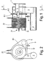
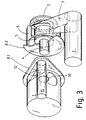
- Reference number 1 is used to mark the swirl chamber (CMR chamber), into which fuel is brought with the aid of supporting air from pipe 11 through connection 12, which is set tangentially to swirl chamber 1.
- a flange 8.1 At the end of swirl chamber 1 is a flange 8.1, by means of which it is attached to the end 8.2 of secondary chamber 6.
- Outlet duct 4 of the swirl chamber is set through these ends. It extends a short distance into secondary chamber 6, the outlet pipe of which, secondary duct 5, extends at the inner end partly overlapping of outlet duct 4, so that a ring-shaped gap is formed between them.
- Secondary air is brought through pipe 2 and connection 3, which is also set tangentially as connection 12.
- the burner is attached, for example, to the wall of a boiler by flange 7.
- Pilot 2MW Units Diameter of CMR chamber 200 895 mm Length of CMR chamber 150 450 mm Diameter of outlet pipe 50 250 mm Height of inlet duct 23 mm Length of inlet duct 450 mm
- Properties of sawdust Mass ratio of water/solids 0,06 0,06 Maximum particle size 5 5 mm Average particle size 1 1 mm
- the amount of air for sub-stoichiometric combustion in swirl chamber 1, i.e. in the CMR chamber, is controlled so that the temperature in the jacket settles to 450 - 650°C. This generally corresponds to 25-35 % of the consumption of oxygen taking place in the swirl chamber.
- a temperature range of 450-550°C is used with organic fuel, and a range of 550 - 650°C is used with, for example, anthracite.
- the secondary airflow is a concentric toroidal flow, most advantageously it is a vortical flow around the primary flow. It is also important that the secondary duct 5 is so close to end 8.2, that a pressure loss is created between them, which evens the toroidal flow.
- the ratio of the length to the diameter of swirl chamber 1 is most advantageously 0,5 - 1,1.
- the length of the secondary chamber 6 is most advantageously 30 - 50 % of the length of swirl chamber 1.
- the outlet duct 4 and the secondary chamber outlet pipe, secondary duct 5 most advantageously overlap by 20 - 30 % of the diameter of the outlet duct.
- the diameter of the outlet duct 4 is most advantageously 25 - 35 % of the diameter of swirl chamber 1.
- the outlet duct 4 extends advantageously also inside the swirl chamber 1 by 5 - 10 % of its diameter, which particularly improves the selectivity of the swirl chamber.
- the question is not primarily of separation, but rather of the processing of solid particles into gas compounds and small coke particles. These all leave the swirl chamber through the outlet duct.
- inert particulate material in the swirl chamber is advantageous, which improves the grinding of the solid fuel and increases the thermal capacity by evening combustion.
- the use of an inert substance can often be arranged so that only as much of it is fed in as leaves to a small extent from the swirl chamber.
- Figure 4 shows a larger output burner, which here is set vertically, when, besides the normal boiler structures, a second fluid bed can be set up, for example in a drier, which is located on top of the burner.
- the same reference numbers as above are used for components that are operationally similar.
- a swirl chamber 1 in the burner its outlet duct 4, a feed duct 12, a secondary chamber 6, and a secondary duct 5.
- the swirl chamber 1, the outlet duct 4, the secondary chamber 6, the secondary duct 5, and the collar 16 described later are all concentric cylindrical components.
- the burner is set on the base of the firebox 17 of the boiler or similar.
- Fuel is blown, by means of a controlled amount of air, from the inlet connection 12 tangentially into the swirl chamber 1.
- the inlet connection 12 is the length of the chamber and its height is 2,6 % of the diameter.
- the height is advantageously 2 - 4 %.
- the angular momentum of the fuel flow and the geometry of the chamber determine the delay time, which further determine the size of the escaping particles. The larger the size of the escaping particles, the longer the flame created. According to a typical criterion, the maximum size of the escaping particles is 0,1 mm, in which case the length of the flame remains reasonable.
- the secondary chamber 6 surrounds swirl chamber 1 and secondary blowing is guided to scavenge the outer surfaces of the swirl chamber 1.
- a similar gap to that above remains in the area of mutual overlapping between the outlet duct 4 of the swirl chamber 1 and the secondary duct 5 of the secondary chamber 6.
- Secondary blowing is directed through this ring-shaped gap as a vortical flow around the main flow.
- the secondary blowing creates angular momentum with the aid of wings 13.
- Eight wings are welded to the outer end of the swirl chamber at an angle of 23° to the radius. These give the secondary blowing a rotation with the same direction as that of the main flow of the outlet duct 4. On the other side, the wings 13' even out the blowing above the swirl chamber 1.
- the swirl chamber 1 is supported from the secondary chamber 6 on four retainers 24.
- the swirl chamber 1 supports lugs 21, inside which sensors are placed to measure the temperature of the jacket.
- the burner can be dismantled from below by opening hatch 25, through which swirl chamber 1 can be removed.
- the secondary airflow of duct 19 is divided here into two parts, so that secondary air is led through valve 18 to distribution duct 2, to which secondary chamber 6 is connected, while the secondary air is distributed in the manner described above. Air is also led from distribution duct 19 to duct 14, which has a ring-shaped opening between collar 16 and secondary duct 5. A third toroidal flow is blown from this.
- valve 18 is closed and the swirl chamber is heated by means of resistances 22, when it is possible to ignite the flow of fuel using an auxiliary flame. After this, the temperature of the swirl chamber 1 is adjusted on the one hand by adjusting valve 18 and on the other by controlling the fuel-air ratio. The total secondary airflow is controlled using valve 15.
- 1,2 MW output was obtained from the burner when the input consisted of 65 g/s of sawdust with a moisture content of 10 %, 200 g/s of primary air, and 2,6 kg/s (total) of secondary air.
- the stoichiometric amount of air would have been only 0,37 kg/s, but is this case the burner was also connected to a fuel dryer.
- the flow velocity of the input air was about 16 m/s.
- the adjustment values of the burner are determined by, among other things, the length that the flame is set to. This sets the limit value for the maximum size of the particles escaping from the swirl chamber. The fuel particles must then be given such a great angular momentum, that the large particles remain in the swirl chamber for a sufficient length of time and that when colliding and burning during this time they reach the maximum size permitted.
- the set criterion is easily fulfilled, in which case the air can be fed to the swirl chamber separately and the fuel feed can be to some extent fragmentary.
Landscapes
- Engineering & Computer Science (AREA)
- Chemical & Material Sciences (AREA)
- Combustion & Propulsion (AREA)
- Mechanical Engineering (AREA)
- General Engineering & Computer Science (AREA)
- Devices And Processes Conducted In The Presence Of Fluids And Solid Particles (AREA)
- Physical Or Chemical Processes And Apparatus (AREA)
Claims (14)
- Verfahren zur Aufbereitung eine breite Teilchengrößenverteilung aufweisender Brennstoffe, bei dem Brennstoff mit Hilfe eines Luftstroms tangential in die brennendes Material enthaltende Wirbelkammer (1) eingetragen (12) und so ein Wirbel erzeugt wird, aus dessen Zentrum der Materialstrom aus der Wirbelkammer abgeführt (4) wird, dadurch gekennzeichnet, dassder durch das Einspeisen des Brennstoff-Luft-Gemischs bewirkte Wirbel und der Durchmessers des abgehenden Stroms so abgestimmt sind, dass für die groben Teilchen eine selektive Verweilzeit dergestalt erreicht wird, dass sich die Größe der Teilchen infolge der durch Verdampfung, Pyrolyse und Gegeneinanderprallen bewirkten mechanischen Behandlung auf einen Wert unterhalb eines gewünschten Grenzwertes verringert bevor sie aus der Wirbelkammer abgehen, und dassdie Temperatur des Zylindermantels der Wirbelkammer (1) unterhalb des Aschenschmelzpunktes gehalten wird, undeine mit Sekundärkanal (5) ausgerüstete Sekundärkammer (6) eingesetzt wird, wobei dieser Sekundärkanal (5) einen den aus der Wirbelkammer abgehenden Luftstrom umgebenden Sekundärluftstrom bildet.
- Verfahren nach Anspruch 1 insbesondere für Flammenverbrennung, dadurch gekennzeichnet, dass die Luftzufuhr in zwei oder mehr Stufen unterteilt wird, wobei in der ersten Stufe das zu verbrennende Material zusammen mit einer unterstöchiometrischen Luftmenge in die Wirbelkammer (1) eingetragen und in der folgenden Stufe ein Sekundärluftstrom in Form eines konzentrischen, ringförmigen Stroms um den aus der Wirbelkammer abgehenden Strom gelegt wird.
- Verfahren nach Anspruch 2, dadurch gekennzeichnet, dass der Sekundärlufstrom in Form eines zum Primärstrom konzentrischen und gleichgerichteten Wirbels gebildet wird.
- Verfahren nach Anspruch 2 oder 3 dadurch gekennzeichnet, dass der Sekundärluftstrom zwecks Kühlens der Wirbelkammer (1) über diese hinweg geführt wird.
- Verfahren nach irgendeinem der Ansprüche 1 bis 3, dadurch gekennzeichnet, dass die Temperatur des zylindrischen Mantels der Wirbelkammer (1) auf einem Wert im Bereich zwischen 450 und 650 °C gehalten wird.
- Verfahren nach irgendeinem der Ansprüche 1 bis 3, dadurch gekennzeichnet, dass in die Wirbelkammer (1) auch inertes körniges Material eingetragen wird.
- Zur Aufbereitung eine breite Teilchengrößenverteilung aufweisender fester Stoffe insbesondere für die Flammenverbrennung dienender Reaktor, der eine im Wesentlichen zylindrische Wirbelkammer (1) mit tangentialen Brennstoff- und Lufteintrittsstutzen (12) und einem zentrischen Abführungskanal (4) hat, dadurch gekennzeichnet, dass der Brennstoff- und Lufteintrittsstutzen der Wirbelkammer, um mit Hilfe des gesamten Primärstroms dem Brennstoff einen Drall zu verleihen, zusammengelegt sind, und dass der Brenner eine Sekundärkammer (6) mit einem zum Abführungskanal (4) konzentrischen, im Durchmesser größeren Sekundärkanal aufweist, der konzentrisch so hinter der Wirbelkammer (1) angeordnet ist, dass sich der besagte Abführungskanal (4) ein Stück in die Sekundärkammer (6) hinein erstreckt und der Sekundärkanal (5) aus der entgegengesetzten Richtung teilweise den Abführungskanal (4) überlappt, so dass diese beiden Kanäle einen ringförmigen Spalt bilden, über den ein Sekundärluftstrom aus der Sekundärkammer um den Hauptstrom herum gelegt wird.
- Reaktor nach Anspruch 7, dadurch gekennzeichnet, dass das Verhältnis aus Länge und Durchmesser der Wirbelkammer (1) im Bereich zwischen 0,5 und 1,1 liegt.
- Reaktor nach Anspruch 7 oder 8, dadurch gekennzeichnet, dass der Durchmesser des Abführungskanals (4) 25 bis 35 % des Durchmessers der Wirbelkammer (1) beträgt.
- Reaktor nach Anspruch 7 oder 8, dadurch gekennzeichnet, dass der Abführungskanal (4) um einen Betrag von 5 bis 10 % des Durchmessers der Wirbelkammer (1) in die Wirbelkammer (1) hineinragt.
- Reaktor nach Anspruch 7 oder 8, dadurch gekennzeichnet, dass die Sekundärkammer die Wirbelkammer umgibt und so deren Kühlung bewirkt.
- Reaktor nach Anspruch 7 oder 8, dadurch gekennzeichnet, dass sich der Abführungskanal (4) und der Sekundärkammer-Abführungskanal (5) um 20 bis 30 % des Abführungskanaldurchmessers überlappen.
- Reaktor nach Anspruch 7 oder 8, dadurch gekennzeichnet, dass sich der Eintrittsstutzen über die gesamte Länge der Wirbelkammer erstreckt.
- Reaktor nach Anspruch 13, dadurch gekennzeichnet, dass die radiale Höhe des Eintrittsstutzens (12) 2 bis 4 % des Durchmessers der Wirbelkammer beträgt.
Applications Claiming Priority (3)
| Application Number | Priority Date | Filing Date | Title |
|---|---|---|---|
| FI954595A FI98854C (fi) | 1995-06-19 | 1995-09-28 | Menetelmä ja poltin nestemäisten ja laajan hiukkaskokojakauman omaavien kiinteiden aineiden polttamiseksi |
| FI954595 | 1995-09-28 | ||
| PCT/FI1996/000514 WO1997012177A1 (en) | 1995-09-28 | 1996-09-30 | Method and reactor for processing of fuels having a wide particle size distribution |
Publications (2)
| Publication Number | Publication Date |
|---|---|
| EP0852686A1 EP0852686A1 (de) | 1998-07-15 |
| EP0852686B1 true EP0852686B1 (de) | 2001-07-25 |
Family
ID=8544104
Family Applications (1)
| Application Number | Title | Priority Date | Filing Date |
|---|---|---|---|
| EP96931834A Expired - Lifetime EP0852686B1 (de) | 1995-09-28 | 1996-09-30 | Verfahren und reaktor zur behandlung von brennstoffen mit einer breiten teilchengrössenverteilung |
Country Status (8)
| Country | Link |
|---|---|
| US (1) | US6202578B1 (de) |
| EP (1) | EP0852686B1 (de) |
| AT (1) | ATE203593T1 (de) |
| AU (1) | AU7087396A (de) |
| CA (1) | CA2231839A1 (de) |
| DE (1) | DE69614124T2 (de) |
| DK (1) | DK0852686T3 (de) |
| WO (1) | WO1997012177A1 (de) |
Families Citing this family (4)
| Publication number | Priority date | Publication date | Assignee | Title |
|---|---|---|---|---|
| FI3296U1 (fi) * | 1997-09-10 | 1998-02-24 | Vapo Oy | Sovitelma tavanomaisen öljykattilan muuntamiseksi kostealle raemaiselle kiinteälle polttoaineelle |
| SE522006C2 (sv) * | 2002-05-29 | 2004-01-07 | Tps Termiska Processer Ab | Styrning av en cyklonbrännare |
| US9903586B2 (en) | 2013-12-13 | 2018-02-27 | Marty Blotter | Waste oil burner |
| KR102369474B1 (ko) * | 2013-12-19 | 2022-03-02 | 타타 스틸 네덜란드 테크날러지 베.뷔. | 제련 사이클론의 동작 방법 |
Family Cites Families (24)
| Publication number | Priority date | Publication date | Assignee | Title |
|---|---|---|---|---|
| US297900A (en) * | 1884-04-29 | Hay-fork | ||
| SE115625C1 (de) * | ||||
| SE130548C1 (de) * | ||||
| US1918397A (en) * | 1930-03-05 | 1933-07-18 | Jezler Hubert | Firing of steam boilers |
| US2707444A (en) * | 1949-09-15 | 1955-05-03 | Directie Staatsmijnen Nl | Cyclone furnace |
| US2979000A (en) * | 1954-02-16 | 1961-04-11 | Babcock & Wilcox Co | Cyclone furnace unit and method of operating the same |
| DE1096531B (de) * | 1956-07-03 | 1961-01-05 | Kohlenscheidungs Ges Mit Besch | Wirbel- oder Zyklonfeuerung |
| US3357383A (en) * | 1965-08-05 | 1967-12-12 | Golovanov Nikolai Vasilievich | Horizontal cylindrical furnace with removal of liquid slag |
| CA953160A (en) * | 1972-02-01 | 1974-08-20 | Clifford G. Otway | Method and apparatus for mixing and turbulating particulate fuel with air for subsequent combustion |
| CA982412A (en) * | 1973-05-14 | 1976-01-27 | Robert L. Shields | Incinerator |
| DE2527618C2 (de) * | 1975-06-20 | 1985-09-26 | Fritz Dr.-Ing. 8026 Ebenhausen Schoppe | Verfahren und Vorrichtung zur Verbrennung von Kohlenstaub |
| DE2534093A1 (de) * | 1975-07-30 | 1977-04-21 | Konus Kessel Waermetech | Einrichtung zum erwaermen einer gegen ueberhitzung zu schuetzenden waermeuebertragungsfluessigkeit |
| US4033505A (en) * | 1975-11-17 | 1977-07-05 | Energex Limited | Cyclonic, multiple vortex type fuel burner with air/fuel ratio control system |
| US4147116A (en) * | 1977-09-19 | 1979-04-03 | Coal Tech Inc. | Pulverized coal burner for furnace and operating method |
| US4586443A (en) * | 1977-09-27 | 1986-05-06 | Trw Inc. | Method and apparatus for in-flight combustion of carbonaceous fuels |
| US4326702A (en) * | 1979-10-22 | 1982-04-27 | Oueneau Paul E | Sprinkler burner for introducing particulate material and a gas into a reactor |
| US4565137A (en) * | 1983-08-08 | 1986-01-21 | Aqua-Chem, Inc. | Bio-mass suspension burner |
| GB8334332D0 (en) * | 1983-12-23 | 1984-02-01 | Coal Industry Patents Ltd | Combustors |
| US4989549A (en) * | 1988-10-11 | 1991-02-05 | Donlee Technologies, Inc. | Ultra-low NOx combustion apparatus |
| US4922839A (en) * | 1988-11-28 | 1990-05-08 | Boucher Robert J | Fuel reactor |
| US5129333A (en) * | 1991-06-24 | 1992-07-14 | Aga Ab | Apparatus and method for recycling waste |
| US5220888A (en) * | 1991-08-01 | 1993-06-22 | Institute Of Gas Technology | Cyclonic combustion |
| US5549059A (en) * | 1994-08-26 | 1996-08-27 | Minergy Corp. | Converting paper mill sludge or the like |
| US5697306A (en) * | 1997-01-28 | 1997-12-16 | The Babcock & Wilcox Company | Low NOx short flame burner with control of primary air/fuel ratio for NOx reduction |
-
1996
- 1996-09-30 DE DE69614124T patent/DE69614124T2/de not_active Expired - Lifetime
- 1996-09-30 DK DK96931834T patent/DK0852686T3/da active
- 1996-09-30 EP EP96931834A patent/EP0852686B1/de not_active Expired - Lifetime
- 1996-09-30 AT AT96931834T patent/ATE203593T1/de active
- 1996-09-30 WO PCT/FI1996/000514 patent/WO1997012177A1/en not_active Ceased
- 1996-09-30 US US09/043,551 patent/US6202578B1/en not_active Expired - Fee Related
- 1996-09-30 AU AU70873/96A patent/AU7087396A/en not_active Abandoned
- 1996-09-30 CA CA002231839A patent/CA2231839A1/en not_active Abandoned
Also Published As
| Publication number | Publication date |
|---|---|
| EP0852686A1 (de) | 1998-07-15 |
| AU7087396A (en) | 1997-04-17 |
| DE69614124T2 (de) | 2002-03-21 |
| DK0852686T3 (da) | 2001-11-12 |
| DE69614124D1 (de) | 2001-08-30 |
| CA2231839A1 (en) | 1997-04-03 |
| ATE203593T1 (de) | 2001-08-15 |
| WO1997012177A1 (en) | 1997-04-03 |
| US6202578B1 (en) | 2001-03-20 |
Similar Documents
| Publication | Publication Date | Title |
|---|---|---|
| US4532873A (en) | Suspension firing of hog fuel, other biomass or peat | |
| US5823122A (en) | System and process for production of fuel gas from solid biomass fuel and for combustion of such fuel gas | |
| US4253409A (en) | Coal burning arrangement | |
| EP0022454B1 (de) | Öfen mit Düsensätzen für die tangentiale Zufuhr pulverisierter Kohle, Luft und rückgeführter Abgase | |
| US4565137A (en) | Bio-mass suspension burner | |
| US4254715A (en) | Solid fuel combustor and method of burning | |
| PL206626B1 (pl) | Palnik do paliwa stałego oraz sposób spalania za pomocą palnika do paliwa stałego | |
| SK278148B6 (en) | Method of mixed combustion of coal and device for realization of this method | |
| US3699903A (en) | Method for improving fuel combustion in a furnace and for reducing pollutant emissions therefrom | |
| EP0238907B1 (de) | Tangentialfeuerung mit niedrigem Luftüberschuss | |
| US7004089B2 (en) | Combined fluidized bed and pulverized coal combustion method | |
| US3199476A (en) | Apparatus and method for compound cyclone combustion of coal and other fuels | |
| KR870002006B1 (ko) | 석탄로의 미분석탄 공급장치 | |
| EP0530969B1 (de) | Kessel mit zirkulierender Wirbelschicht | |
| US6202578B1 (en) | Method and reactor for processing of fuels having a wide particle size distribution | |
| CA1089717A (en) | Hot gas recirculation type burning furnace | |
| US4614492A (en) | Burner for burning pulverulent fuel | |
| EP3535521B1 (de) | Mehrkammer-verbrennungsanlage zur turbulenten verbrennung von feststoff- und biomassebrennstoffen | |
| EP0902235B1 (de) | Anordnung zum Umbau eines ölbetriebenen Heizkessels in einen mit wasserhaltigem, körnigem Brennstoff arbeitenden Heizkessel | |
| AU574498B2 (en) | Suspension firing of hog fuel. | |
| EP0155120A2 (de) | Verfahren zum Betrieb eines Kohlebrenners | |
| US2856872A (en) | Pulverized coal firing system | |
| EP0156048A1 (de) | Kohlebrenner | |
| SK150794A3 (en) | Torch for combustion of lignitic dust | |
| FI98854C (fi) | Menetelmä ja poltin nestemäisten ja laajan hiukkaskokojakauman omaavien kiinteiden aineiden polttamiseksi |
Legal Events
| Date | Code | Title | Description |
|---|---|---|---|
| PUAI | Public reference made under article 153(3) epc to a published international application that has entered the european phase |
Free format text: ORIGINAL CODE: 0009012 |
|
| 17P | Request for examination filed |
Effective date: 19980420 |
|
| AK | Designated contracting states |
Kind code of ref document: A1 Designated state(s): AT BE CH DE DK ES FR GB GR IE IT LI NL PT SE |
|
| 17Q | First examination report despatched |
Effective date: 19991214 |
|
| GRAG | Despatch of communication of intention to grant |
Free format text: ORIGINAL CODE: EPIDOS AGRA |
|
| GRAG | Despatch of communication of intention to grant |
Free format text: ORIGINAL CODE: EPIDOS AGRA |
|
| GRAH | Despatch of communication of intention to grant a patent |
Free format text: ORIGINAL CODE: EPIDOS IGRA |
|
| GRAH | Despatch of communication of intention to grant a patent |
Free format text: ORIGINAL CODE: EPIDOS IGRA |
|
| GRAA | (expected) grant |
Free format text: ORIGINAL CODE: 0009210 |
|
| AK | Designated contracting states |
Kind code of ref document: B1 Designated state(s): AT BE CH DE DK ES FR GB GR IE IT LI NL PT SE |
|
| REF | Corresponds to: |
Ref document number: 203593 Country of ref document: AT Date of ref document: 20010815 Kind code of ref document: T |
|
| REG | Reference to a national code |
Ref country code: CH Ref legal event code: EP |
|
| REG | Reference to a national code |
Ref country code: IE Ref legal event code: FG4D |
|
| REF | Corresponds to: |
Ref document number: 69614124 Country of ref document: DE Date of ref document: 20010830 |
|
| REG | Reference to a national code |
Ref country code: CH Ref legal event code: NV Representative=s name: WILLIAM BLANC & CIE CONSEILS EN PROPRIETE INDUSTRI |
|
| PG25 | Lapsed in a contracting state [announced via postgrant information from national office to epo] |
Ref country code: PT Free format text: LAPSE BECAUSE OF FAILURE TO SUBMIT A TRANSLATION OF THE DESCRIPTION OR TO PAY THE FEE WITHIN THE PRESCRIBED TIME-LIMIT Effective date: 20011025 |
|
| PG25 | Lapsed in a contracting state [announced via postgrant information from national office to epo] |
Ref country code: GR Free format text: LAPSE BECAUSE OF FAILURE TO SUBMIT A TRANSLATION OF THE DESCRIPTION OR TO PAY THE FEE WITHIN THE PRESCRIBED TIME-LIMIT Effective date: 20011026 |
|
| REG | Reference to a national code |
Ref country code: DK Ref legal event code: T3 |
|
| ET | Fr: translation filed | ||
| REG | Reference to a national code |
Ref country code: GB Ref legal event code: IF02 |
|
| PG25 | Lapsed in a contracting state [announced via postgrant information from national office to epo] |
Ref country code: ES Free format text: LAPSE BECAUSE OF FAILURE TO SUBMIT A TRANSLATION OF THE DESCRIPTION OR TO PAY THE FEE WITHIN THE PRESCRIBED TIME-LIMIT Effective date: 20020131 |
|
| PLBE | No opposition filed within time limit |
Free format text: ORIGINAL CODE: 0009261 |
|
| STAA | Information on the status of an ep patent application or granted ep patent |
Free format text: STATUS: NO OPPOSITION FILED WITHIN TIME LIMIT |
|
| 26N | No opposition filed | ||
| REG | Reference to a national code |
Ref country code: CH Ref legal event code: PFA Owner name: VAPO OY Free format text: VAPO OY#YRJOENKATU 42#40100 JYVAESKYLAE (FI) -TRANSFER TO- VAPO OY#YRJOENKATU 42#40100 JYVAESKYLAE (FI) |
|
| PGFP | Annual fee paid to national office [announced via postgrant information from national office to epo] |
Ref country code: IE Payment date: 20100903 Year of fee payment: 15 Ref country code: CH Payment date: 20100923 Year of fee payment: 15 |
|
| PGFP | Annual fee paid to national office [announced via postgrant information from national office to epo] |
Ref country code: SE Payment date: 20100912 Year of fee payment: 15 Ref country code: AT Payment date: 20100909 Year of fee payment: 15 |
|
| PGFP | Annual fee paid to national office [announced via postgrant information from national office to epo] |
Ref country code: GB Payment date: 20100908 Year of fee payment: 15 |
|
| PGFP | Annual fee paid to national office [announced via postgrant information from national office to epo] |
Ref country code: NL Payment date: 20100929 Year of fee payment: 15 Ref country code: FR Payment date: 20101008 Year of fee payment: 15 Ref country code: DK Payment date: 20100907 Year of fee payment: 15 |
|
| PGFP | Annual fee paid to national office [announced via postgrant information from national office to epo] |
Ref country code: DE Payment date: 20100930 Year of fee payment: 15 |
|
| PGFP | Annual fee paid to national office [announced via postgrant information from national office to epo] |
Ref country code: BE Payment date: 20101124 Year of fee payment: 15 Ref country code: IT Payment date: 20100929 Year of fee payment: 15 |
|
| REG | Reference to a national code |
Ref country code: CH Ref legal event code: PCAR Free format text: NOVAGRAAF SWITZERLAND SA;CHEMIN DE L'ECHO 3;1213 ONEX (CH) |
|
| REG | Reference to a national code |
Ref country code: DE Ref legal event code: R231 Ref document number: 69614124 Country of ref document: DE |
|
| PG25 | Lapsed in a contracting state [announced via postgrant information from national office to epo] |
Ref country code: DE Free format text: LAPSE BECAUSE OF THE APPLICANT RENOUNCES Effective date: 20110905 |
|
| BERE | Be: lapsed |
Owner name: *VAPO OY Effective date: 20110930 |
|
| REG | Reference to a national code |
Ref country code: NL Ref legal event code: V1 Effective date: 20120401 |
|
| REG | Reference to a national code |
Ref country code: CH Ref legal event code: PL Ref country code: DK Ref legal event code: EBP |
|
| GBPC | Gb: european patent ceased through non-payment of renewal fee |
Effective date: 20110930 |
|
| PG25 | Lapsed in a contracting state [announced via postgrant information from national office to epo] |
Ref country code: IT Free format text: LAPSE BECAUSE OF NON-PAYMENT OF DUE FEES Effective date: 20110930 |
|
| REG | Reference to a national code |
Ref country code: FR Ref legal event code: ST Effective date: 20120531 |
|
| PG25 | Lapsed in a contracting state [announced via postgrant information from national office to epo] |
Ref country code: BE Free format text: LAPSE BECAUSE OF NON-PAYMENT OF DUE FEES Effective date: 20110930 |
|
| REG | Reference to a national code |
Ref country code: SE Ref legal event code: EUG |
|
| REG | Reference to a national code |
Ref country code: IE Ref legal event code: MM4A |
|
| PG25 | Lapsed in a contracting state [announced via postgrant information from national office to epo] |
Ref country code: CH Free format text: LAPSE BECAUSE OF NON-PAYMENT OF DUE FEES Effective date: 20110930 Ref country code: NL Free format text: LAPSE BECAUSE OF NON-PAYMENT OF DUE FEES Effective date: 20120401 Ref country code: LI Free format text: LAPSE BECAUSE OF NON-PAYMENT OF DUE FEES Effective date: 20110930 Ref country code: IE Free format text: LAPSE BECAUSE OF NON-PAYMENT OF DUE FEES Effective date: 20110930 |
|
| PG25 | Lapsed in a contracting state [announced via postgrant information from national office to epo] |
Ref country code: FR Free format text: LAPSE BECAUSE OF NON-PAYMENT OF DUE FEES Effective date: 20110930 Ref country code: GB Free format text: LAPSE BECAUSE OF NON-PAYMENT OF DUE FEES Effective date: 20110930 |
|
| PG25 | Lapsed in a contracting state [announced via postgrant information from national office to epo] |
Ref country code: SE Free format text: LAPSE BECAUSE OF NON-PAYMENT OF DUE FEES Effective date: 20111001 Ref country code: DK Free format text: LAPSE BECAUSE OF NON-PAYMENT OF DUE FEES Effective date: 20110930 |
|
| REG | Reference to a national code |
Ref country code: AT Ref legal event code: MM01 Ref document number: 203593 Country of ref document: AT Kind code of ref document: T Effective date: 20110930 |
|
| PG25 | Lapsed in a contracting state [announced via postgrant information from national office to epo] |
Ref country code: AT Free format text: LAPSE BECAUSE OF NON-PAYMENT OF DUE FEES Effective date: 20110930 |