EP0852963B1 - Séparateur à enroulement direct de particules d'un mélange gazeux et son utilisation en craquage thermique ou catalytique en lit fluidisé - Google Patents
Séparateur à enroulement direct de particules d'un mélange gazeux et son utilisation en craquage thermique ou catalytique en lit fluidisé Download PDFInfo
- Publication number
- EP0852963B1 EP0852963B1 EP98400021A EP98400021A EP0852963B1 EP 0852963 B1 EP0852963 B1 EP 0852963B1 EP 98400021 A EP98400021 A EP 98400021A EP 98400021 A EP98400021 A EP 98400021A EP 0852963 B1 EP0852963 B1 EP 0852963B1
- Authority
- EP
- European Patent Office
- Prior art keywords
- zone
- outlet
- reactor
- angle
- particles
- Prior art date
- Legal status (The legal status is an assumption and is not a legal conclusion. Google has not performed a legal analysis and makes no representation as to the accuracy of the status listed.)
- Expired - Lifetime
Links
- 239000002245 particle Substances 0.000 title claims abstract description 60
- 239000008246 gaseous mixture Substances 0.000 title abstract description 3
- 238000000926 separation method Methods 0.000 claims abstract description 56
- 230000007704 transition Effects 0.000 claims abstract description 51
- 239000000203 mixture Substances 0.000 claims abstract description 30
- 229930195733 hydrocarbon Natural products 0.000 claims abstract description 16
- 150000002430 hydrocarbons Chemical class 0.000 claims abstract description 16
- 239000007789 gas Substances 0.000 claims description 45
- 239000007787 solid Substances 0.000 claims description 34
- 239000004215 Carbon black (E152) Substances 0.000 claims description 11
- 239000003054 catalyst Substances 0.000 claims description 10
- 238000004523 catalytic cracking Methods 0.000 claims description 7
- 239000012530 fluid Substances 0.000 claims description 5
- 230000001133 acceleration Effects 0.000 claims description 4
- 238000011144 upstream manufacturing Methods 0.000 claims description 3
- 230000003197 catalytic effect Effects 0.000 abstract description 6
- 238000004804 winding Methods 0.000 description 63
- 238000006243 chemical reaction Methods 0.000 description 35
- 239000000047 product Substances 0.000 description 15
- 235000021183 entrée Nutrition 0.000 description 8
- 230000000149 penetrating effect Effects 0.000 description 6
- 230000000694 effects Effects 0.000 description 5
- 238000000034 method Methods 0.000 description 5
- JTJMJGYZQZDUJJ-UHFFFAOYSA-N phencyclidine Chemical class C1CCCCN1C1(C=2C=CC=CC=2)CCCCC1 JTJMJGYZQZDUJJ-UHFFFAOYSA-N 0.000 description 5
- 230000008569 process Effects 0.000 description 5
- 238000007493 shaping process Methods 0.000 description 5
- 230000008859 change Effects 0.000 description 4
- 239000000571 coke Substances 0.000 description 4
- 239000012071 phase Substances 0.000 description 4
- XLYOFNOQVPJJNP-UHFFFAOYSA-N water Chemical compound O XLYOFNOQVPJJNP-UHFFFAOYSA-N 0.000 description 4
- 238000004891 communication Methods 0.000 description 3
- 238000005336 cracking Methods 0.000 description 3
- 238000005243 fluidization Methods 0.000 description 3
- 230000008929 regeneration Effects 0.000 description 3
- 238000011069 regeneration method Methods 0.000 description 3
- 238000004227 thermal cracking Methods 0.000 description 3
- QGZKDVFQNNGYKY-UHFFFAOYSA-N Ammonia Chemical compound N QGZKDVFQNNGYKY-UHFFFAOYSA-N 0.000 description 2
- IJGRMHOSHXDMSA-UHFFFAOYSA-N Atomic nitrogen Chemical compound N#N IJGRMHOSHXDMSA-UHFFFAOYSA-N 0.000 description 2
- CURLTUGMZLYLDI-UHFFFAOYSA-N Carbon dioxide Chemical compound O=C=O CURLTUGMZLYLDI-UHFFFAOYSA-N 0.000 description 2
- 230000007423 decrease Effects 0.000 description 2
- 238000007599 discharging Methods 0.000 description 2
- 239000007788 liquid Substances 0.000 description 2
- 230000033001 locomotion Effects 0.000 description 2
- VNWKTOKETHGBQD-UHFFFAOYSA-N methane Chemical compound C VNWKTOKETHGBQD-UHFFFAOYSA-N 0.000 description 2
- 230000006798 recombination Effects 0.000 description 2
- 238000005215 recombination Methods 0.000 description 2
- 238000012360 testing method Methods 0.000 description 2
- OTMSDBZUPAUEDD-UHFFFAOYSA-N Ethane Chemical compound CC OTMSDBZUPAUEDD-UHFFFAOYSA-N 0.000 description 1
- 241000287107 Passer Species 0.000 description 1
- 229910021529 ammonia Inorganic materials 0.000 description 1
- 230000001174 ascending effect Effects 0.000 description 1
- 238000009835 boiling Methods 0.000 description 1
- 229910002092 carbon dioxide Inorganic materials 0.000 description 1
- 239000001569 carbon dioxide Substances 0.000 description 1
- 238000006555 catalytic reaction Methods 0.000 description 1
- 239000007795 chemical reaction product Substances 0.000 description 1
- 239000012084 conversion product Substances 0.000 description 1
- 238000001816 cooling Methods 0.000 description 1
- 230000003247 decreasing effect Effects 0.000 description 1
- 239000007857 degradation product Substances 0.000 description 1
- 238000011143 downstream manufacturing Methods 0.000 description 1
- 239000000428 dust Substances 0.000 description 1
- 239000010419 fine particle Substances 0.000 description 1
- 230000004907 flux Effects 0.000 description 1
- 239000007792 gaseous phase Substances 0.000 description 1
- 239000007943 implant Substances 0.000 description 1
- 238000011044 inertial separation Methods 0.000 description 1
- 238000002347 injection Methods 0.000 description 1
- 239000007924 injection Substances 0.000 description 1
- 238000012423 maintenance Methods 0.000 description 1
- 238000012986 modification Methods 0.000 description 1
- 230000004048 modification Effects 0.000 description 1
- 239000003607 modifier Substances 0.000 description 1
- 229910052757 nitrogen Inorganic materials 0.000 description 1
- 230000003071 parasitic effect Effects 0.000 description 1
- 230000000704 physical effect Effects 0.000 description 1
- 238000012545 processing Methods 0.000 description 1
- 230000000750 progressive effect Effects 0.000 description 1
- 230000009467 reduction Effects 0.000 description 1
- 239000011343 solid material Substances 0.000 description 1
- 239000007921 spray Substances 0.000 description 1
- -1 steam Chemical compound 0.000 description 1
- 239000000725 suspension Substances 0.000 description 1
Images
Classifications
-
- B—PERFORMING OPERATIONS; TRANSPORTING
- B04—CENTRIFUGAL APPARATUS OR MACHINES FOR CARRYING-OUT PHYSICAL OR CHEMICAL PROCESSES
- B04C—APPARATUS USING FREE VORTEX FLOW, e.g. CYCLONES
- B04C7/00—Apparatus not provided for in group B04C1/00, B04C3/00, or B04C5/00; Multiple arrangements not provided for in one of the groups B04C1/00, B04C3/00, or B04C5/00; Combinations of apparatus covered by two or more of the groups B04C1/00, B04C3/00, or B04C5/00
-
- B—PERFORMING OPERATIONS; TRANSPORTING
- B01—PHYSICAL OR CHEMICAL PROCESSES OR APPARATUS IN GENERAL
- B01D—SEPARATION
- B01D45/00—Separating dispersed particles from gases or vapours by gravity, inertia, or centrifugal forces
- B01D45/12—Separating dispersed particles from gases or vapours by gravity, inertia, or centrifugal forces by centrifugal forces
-
- B—PERFORMING OPERATIONS; TRANSPORTING
- B01—PHYSICAL OR CHEMICAL PROCESSES OR APPARATUS IN GENERAL
- B01D—SEPARATION
- B01D53/00—Separation of gases or vapours; Recovering vapours of volatile solvents from gases; Chemical or biological purification of waste gases, e.g. engine exhaust gases, smoke, fumes, flue gases, aerosols
- B01D53/24—Separation of gases or vapours; Recovering vapours of volatile solvents from gases; Chemical or biological purification of waste gases, e.g. engine exhaust gases, smoke, fumes, flue gases, aerosols by centrifugal force
-
- B—PERFORMING OPERATIONS; TRANSPORTING
- B01—PHYSICAL OR CHEMICAL PROCESSES OR APPARATUS IN GENERAL
- B01J—CHEMICAL OR PHYSICAL PROCESSES, e.g. CATALYSIS OR COLLOID CHEMISTRY; THEIR RELEVANT APPARATUS
- B01J8/00—Chemical or physical processes in general, conducted in the presence of fluids and solid particles; Apparatus for such processes
- B01J8/005—Separating solid material from the gas/liquid stream
-
- B—PERFORMING OPERATIONS; TRANSPORTING
- B01—PHYSICAL OR CHEMICAL PROCESSES OR APPARATUS IN GENERAL
- B01J—CHEMICAL OR PHYSICAL PROCESSES, e.g. CATALYSIS OR COLLOID CHEMISTRY; THEIR RELEVANT APPARATUS
- B01J8/00—Chemical or physical processes in general, conducted in the presence of fluids and solid particles; Apparatus for such processes
- B01J8/005—Separating solid material from the gas/liquid stream
- B01J8/0055—Separating solid material from the gas/liquid stream using cyclones
-
- B—PERFORMING OPERATIONS; TRANSPORTING
- B01—PHYSICAL OR CHEMICAL PROCESSES OR APPARATUS IN GENERAL
- B01J—CHEMICAL OR PHYSICAL PROCESSES, e.g. CATALYSIS OR COLLOID CHEMISTRY; THEIR RELEVANT APPARATUS
- B01J8/00—Chemical or physical processes in general, conducted in the presence of fluids and solid particles; Apparatus for such processes
- B01J8/18—Chemical or physical processes in general, conducted in the presence of fluids and solid particles; Apparatus for such processes with fluidised particles
-
- B—PERFORMING OPERATIONS; TRANSPORTING
- B01—PHYSICAL OR CHEMICAL PROCESSES OR APPARATUS IN GENERAL
- B01J—CHEMICAL OR PHYSICAL PROCESSES, e.g. CATALYSIS OR COLLOID CHEMISTRY; THEIR RELEVANT APPARATUS
- B01J8/00—Chemical or physical processes in general, conducted in the presence of fluids and solid particles; Apparatus for such processes
- B01J8/18—Chemical or physical processes in general, conducted in the presence of fluids and solid particles; Apparatus for such processes with fluidised particles
- B01J8/24—Chemical or physical processes in general, conducted in the presence of fluids and solid particles; Apparatus for such processes with fluidised particles according to "fluidised-bed" technique
- B01J8/34—Chemical or physical processes in general, conducted in the presence of fluids and solid particles; Apparatus for such processes with fluidised particles according to "fluidised-bed" technique with stationary packing material in the fluidised bed, e.g. bricks, wire rings, baffles
-
- B—PERFORMING OPERATIONS; TRANSPORTING
- B07—SEPARATING SOLIDS FROM SOLIDS; SORTING
- B07B—SEPARATING SOLIDS FROM SOLIDS BY SIEVING, SCREENING, SIFTING OR BY USING GAS CURRENTS; SEPARATING BY OTHER DRY METHODS APPLICABLE TO BULK MATERIAL, e.g. LOOSE ARTICLES FIT TO BE HANDLED LIKE BULK MATERIAL
- B07B7/00—Selective separation of solid materials carried by, or dispersed in, gas currents
- B07B7/08—Selective separation of solid materials carried by, or dispersed in, gas currents using centrifugal force
- B07B7/086—Selective separation of solid materials carried by, or dispersed in, gas currents using centrifugal force generated by the winding course of the gas stream
-
- C—CHEMISTRY; METALLURGY
- C10—PETROLEUM, GAS OR COKE INDUSTRIES; TECHNICAL GASES CONTAINING CARBON MONOXIDE; FUELS; LUBRICANTS; PEAT
- C10G—CRACKING HYDROCARBON OILS; PRODUCTION OF LIQUID HYDROCARBON MIXTURES, e.g. BY DESTRUCTIVE HYDROGENATION, OLIGOMERISATION, POLYMERISATION; RECOVERY OF HYDROCARBON OILS FROM OIL-SHALE, OIL-SAND, OR GASES; REFINING MIXTURES MAINLY CONSISTING OF HYDROCARBONS; REFORMING OF NAPHTHA; MINERAL WAXES
- C10G11/00—Catalytic cracking, in the absence of hydrogen, of hydrocarbon oils
- C10G11/14—Catalytic cracking, in the absence of hydrogen, of hydrocarbon oils with preheated moving solid catalysts
- C10G11/18—Catalytic cracking, in the absence of hydrogen, of hydrocarbon oils with preheated moving solid catalysts according to the "fluidised-bed" technique
-
- C—CHEMISTRY; METALLURGY
- C10—PETROLEUM, GAS OR COKE INDUSTRIES; TECHNICAL GASES CONTAINING CARBON MONOXIDE; FUELS; LUBRICANTS; PEAT
- C10G—CRACKING HYDROCARBON OILS; PRODUCTION OF LIQUID HYDROCARBON MIXTURES, e.g. BY DESTRUCTIVE HYDROGENATION, OLIGOMERISATION, POLYMERISATION; RECOVERY OF HYDROCARBON OILS FROM OIL-SHALE, OIL-SAND, OR GASES; REFINING MIXTURES MAINLY CONSISTING OF HYDROCARBONS; REFORMING OF NAPHTHA; MINERAL WAXES
- C10G9/00—Thermal non-catalytic cracking, in the absence of hydrogen, of hydrocarbon oils
- C10G9/28—Thermal non-catalytic cracking, in the absence of hydrogen, of hydrocarbon oils with preheated moving solid material
- C10G9/32—Thermal non-catalytic cracking, in the absence of hydrogen, of hydrocarbon oils with preheated moving solid material according to the "fluidised-bed" technique
Definitions
- the present invention relates to at least one rapid separator with direct winding to separate a particulate solid from a gas and its use in particular in catalytic cracking in a fluidized bed. It can also be used in a thermal cracking apparatus in the presence of substantially inert particles with or without water vapor.
- reaction products are driven to secondary separation and solid particles are recycled at the reactor inlet after having, in some processes, undergone a regeneration to give the particles properties (coke content, activity by example) adequate for the reaction.
- the present invention relates to a device comprising an equipment that allows the rapid separation of the gaseous products and the solid at the reactor outlet, which is particularly suitable for certain conversion processes such as thermal cracking or catalytic cracking of hydrocarbon feeds characterized by the fact that the temperature the output of the reactor is generally sufficiently high to allow reactions secondary degradation products to take place.
- Percevauft (patent FR-1-110-117) describes an original separation system to be positioned at the top of a duct. His system consists in positioning on both sides of the duct two separation chambers in connection with the duct by a volute which initiate a rotation of the flow in the vertical plane. The gas is withdrawn in the middle of the chambers by a penetrating conduit vertically in these chambers at their apex and opening into the separation chamber by a substantially horizontal opening.
- This separation device may have a lower volume than reverse cyclones. It is probably well suited to separation of effluents slightly loaded with dust but probably not at the separation of effluents very charged with particles such as those encountered in the catalytic cracking process.
- the gas exhaust pipes penetrating vertically into the chambers of separation form an obstacle to the flow of the gas-solid suspension when the latter passes from the conduit to the separation chambers.
- the particles form a dense and thick layer on the upper part of the separation chamber and any obstacle, such as the ducts penetrating the evacuation of the gases, favor the re-entrainement of the particles and thus causes a decrease in efficiency of the separation.
- the feeding duct opens without transition into the separation chambers, which causes a deceleration and not an acceleration. This probably allows to separate large particles with sufficient inertia but not the fine particles that have tendency to follow the gaseous currents.
- decreasing speeds implies increase in separation volume, resulting in an increase both in the residence time gases and congestion.
- Van den Akker and Hegidius (EP-0332 277 A2) propose a separation system in which the exhaust pipes are positioned horizontally, the gas entering the separator now rotating around the axis of the gas exhaust ducts.
- the authors specify that separation chambers communicate with each other. Because of this, he It is not possible to establish a uniformly shaped flow prior to implementation. rotation of the flow.
- the gas can recirculate in the separator, that is to say perform a full rotation and return to the inlet area in contact with gas directly from the inlet duct. This induces a tangential velocity gradient important at the beginning of the rotation of the gases in the separation chambers, the speed gas being higher near the walls of the separation chambers and the axis of the duct input.
- the recirculation in the separation chamber causes a increase of back-mixing of the gas in the separator and can therefore induce decreases in selectivity in the case of very fast reactions.
- recirculation of gas increases substantially the pressure drop (or pressure difference) between the inlet and the ducts exhaust gas.
- the transition zone may be vertical, the outer wall 30 of the winding zone may be wound around an angle of 70 to 90 degrees and the deflector 30 to 180 degrees. It is advantageous that the two walls of the substantially vertical winding zone are substantially parallel.
- the output of effluents may consist of a tube whose entry is an orifice pierced on one of the vertical walls of the separator, or two tubes each of which is an orifice pierced on each of the vertical walls.
- the axis of the tube is substantially in a horizontal plane.
- the separator comprises two tubes, these can optionally be combined in one downstream of the separator by adding bends and pipe junctions.
- the superficial velocity of the effluents at the inlet of the outlet tubes is generally between 0.5 and 2 times the speed of the gas in the inlet of the winding zone in the separator and preferably 0.75 to 1 , 25 times that speed. In other words, the sum of the sections of the first effluent outlets is between 0.5 and twice the flow section of the reactor.
- the solids outlet opening between the separator and the solids discharge conduit is generally disposed at an angle axis of between 0 and 45 degrees from the vertical. It can be tangent to the winding.
- the invention also relates to the use of at least one primary separation device according to the invention in an apparatus for thermal cracking of a hydrocarbon mixture in the presence of inert particles and in the presence or absence of water vapor. Finally, it relates to the use of this same separation device in a device for catalytic cracking of a hydrocarbon feedstock.
- the tubular reactor in which the cracking reaction of the fluidized bed feed takes place, in the presence of the catalyst, may be either external or internal to the stripping vessel in which the final separation of the catalyst effluents takes place.
- the output of the gaseous effluents from the primary separator according to the invention is usually connected to at least one secondary separator such as a cyclone, which makes it possible to recover firstly the remaining catalyst, with a view to stripping it and secondly to hydrocarbon effluents substantially free of catalyst (generally less than 0.1% by weight of catalyst generally).
- This secondary separator may be located outside the stripping enclosure. It can be located, according to another variant, inside thereof. In this case, the secondary separator may be located in the vicinity of the outlet of the tube connected to the outlet of the gaseous effluents of the primary separator according to the invention, as will be shown in FIG.
- Said tube then usually comprises a plurality of holes which receive the gaseous effluents resulting from the stripping of the catalyst in the lower part of the stripping enclosure, all the effluents being evacuated by the secondary cyclone outwards in order to further processing.
- the solid discharge ducts open into a separating and stripping enclosure S which may also but not necessarily contain the primary and / or secondary separation means, the lower part of which may be under or above the opening of these exhaust pipes, contains an inventory of divided solids maintained in the so-called fluidization state by means of at least one appropriate injection of gas (such as nitrogen, steam, ammonia, carbon dioxide, methane or ethane located under said ducts and allowing a good distribution of the gas over the entire passage section.
- gas such as nitrogen, steam, ammonia, carbon dioxide, methane or ethane located under said ducts and allowing a good distribution of the gas over the entire passage section.
- gas such as nitrogen, steam, ammonia, carbon dioxide, methane or ethane located under said ducts and allowing a good distribution of the gas over the entire passage section.
- gas such as nitrogen, steam, ammonia, carbon dioxide, methane or ethane located under said ducts and allowing a good distribution of the gas over
- the solids Before being recycled to the inlet of the reactor R, the solids can flow to regeneration means to restore them to the properties they had before their passage through the reaction zone. In the case where the solids are covered with coke during their passage in the reaction zone R, it may thus be necessary to burn this coke in a device for bringing it into contact with air, such as, for example, a set of beds. fluidized, the solids freed of their coke then being recycled to the inlet of the reaction zone.
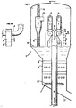
- FIG. 1 depicts a primary separation system used in the case where the reaction zone is an ascending type fluidized catalytic cracking reactor.
- the system proposed in FIG. 1 is particularly useful in the case where the reaction zone R enters the stripping enclosure S, which is then, generally but not necessarily, centered on R, where the solids outlets 8 open out.
- the figure shows a system of two separation chambers substantially symmetrical with respect to the axis of the reaction zone and operating in parallel, the number of chambers generally ranging from 1 to 8 and preferably in this configuration from 2 to 4.
- Each separator (FIG. 1A) consists of two flat faces 6 substantially parallel to the axis of the reaction zone R.
- a transition zone 1 and acceleration makes it possible to shape and accelerate the mixture for each separator between the enclosure R-reaction and a winding zone 3.
- This winding zone 3 defined by an outer wall 30 and the deflector 10 connects to the outside of each transition zone.
- the outer walls of the zones 3 extend at the point of tangency by a wall directed towards the axis of the reactor which prevents communication between the chamber inlets and allows the maintenance of the accelerated flow.
- a rotation of the winding of about 180 ° makes it possible to change the direction of flow of the particles and to press the particles to the wall under the effect of the centrifugal force induced by the winding 3.
- the winding is wound on a central zone 7, which is protected by the deflector 10, preventing any movement between 3 and 7 on a 135 degree angle.
- the gaseous products are evacuated via a non-penetrating evacuation conduit 4, of cylindrical shape whose central axis is substantially coincident with that of the deflector and of the winding zone, and which is connected to the parallel faces 6 of the separator by two openings 5 located respectively on each of the faces 6 of the separator.
- the connection of the evacuation duct 4 and the deflector is made substantially according to the same diameter, to the thickness of the duct near.
- the particles collected at the lower part of the winding are then discharged into a output 9 of solids and channeled in a conduit 8.
- the output 9 is connected tangentially to the winding 3 by its outer wall 31, the inner wall 32 which contains at least one segment tangent to the opening 5 of the outlet pipe of the products 4 connecting to the transition zone.
- the exhaust duct 8 introduces the catalytic particles into a dense fluidized bed 16 of the stripping chamber which is set in motion by a fluidization ring 20. This one delivers a gaseous stream of water vapor, for example necessary for the stripping of hydrocarbons.
- This conduit 8 opens near the level of the dense bed to plus or minus 1 m).
- Horizontal rows 18, 19 of crossed tubes relative to each other allow to improve the distribution of the particles from the ducts 8 and therefore their stripping.
- the stripped catalytic particles are sent via a line 21 connected to the end lower enclosure in a regeneration chamber not shown in Figure 1.
- the gaseous effluent still containing 10 to 20% of particles is introduced through an opening 11 provided on line 4 at the entrance 13 of a separation cyclone 12 to recover substantially all the particles by a leg 15. This input 13 recovers moreover effluents resulting from stripping.
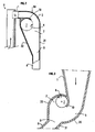
- Figure 2 describes a primary separation system object of the present invention implemented in the case where the reaction zone is an upstream type reactor.
- the system proposed in FIG. 2 is particularly useful in the case where the reaction zone R does not penetrate into the stripping enclosure S. It is then possible to position the transition zone 1 substantially horizontally, the length of the zone of transition 1 then being long enough for the separator to be placed inside S, is sufficiently short for the separator to be placed outside S, the duct 8 then being connected to the wall of the enclosure S.
- the figure represents a single-chamber system, the number of chambers generally ranging from 1 to 8 and preferably in this configuration from 1 to 3.
- the transition zone 1 makes it possible to make a transition as well as a change of direction for each separator between the reaction chamber R and the winding 3.
- the winding 3 connects tangentially outside of each transition zone.
- a rotation of the winding of about 90 ° (between 45 and 135 °) makes it possible to change the direction of flow of the particles and to press the particles to the wall under the effect of the centrifugal force induced by the winding 3.
- the winding is wound on the central zone 7, which is protected by a deflector 10, preventing any circulation between the winding 3 and the central zone 7 for at least 15 ° over the 45 to 135 ° of rotation of the winding 3.
- the products are evacuated via the product outlet duct 4 which is substantially coaxial with the deflector and which is connected to the parallel faces of the separator by two openings located respectively on each of the faces 6 of the separator.
- the collected particles are then discharged into the outlet 9 to the discharge duct 8, the outlet 9 being connected tangentially to the winding 3 for its outer face 31, the internal face containing at least one segment tangential to the opening 5 of the outlet pipe of products 4.
- Figure 3 describes a primary separation system object of the present invention implemented in the case where the reaction zone is a downflow type reactor.
- the system proposed in FIG. 3 can be used in the case where the reaction zone R does not enter the enclosure S or in the opposite case.
- the transition zone 1 can be positioned in the extension of the reactor.
- the figure represents a single-chamber system, the number of chambers generally ranging from 1 to 8 and preferably in this configuration from 1 to 4.
- the transition zone 1 makes it possible to carry out a transition for each separator between the reaction chamber R and the winding 3.
- the winding 3 connects tangentially outside the transition zone.
- a rotation of the winding of about 90 ° makes it possible to change the direction of direction of the flow of the particles and to press the particles to the wall under the effect of the centrifugal force induced by the winding 3.
- the winding necessarily ends when the tangent to the winding meets the horizontal.
- the winding is wound on the central zone 7, which is protected by a deflector 10, preventing any circulation between the winding 3 and the central zone 7 at an angle of at least 15 ° with respect to the angle of 90.degree. ° of rotation of the winding 3.
- the products are discharged through the conduit 4 for discharging the products connected to the parallel faces of the separator by two openings 5 respectively located on each of the faces 6 of the separator.
- This duct 4 is substantially coaxial with the deflector.
- the collected particles are then discharged downwards in the exit zone 9 towards the solids outlet duct 8, the outlet 9 being connected to the winding 3 for its external face, the internal face being able to form a winding between the two parallel faces of the separator being connected tangentially by at least one segment to the opening 5 of the discharge pipes of the products 4.
- the solid discharge tube can be inclined at a maximum of 45 ° with respect to the vertical, which allows possibly to position the separator outside the stripping enclosure S in the case where the reaction zone R is external to the enclosure S.
- the present invention makes it possible to obtain a satisfactory separation when the velocity of the gaseous fluids at the exit of the transition zone and in the winding zone is between 10 and 30 m / s, and preferably between 15 and 25 m / s. .
- the solid load defined as the mass ratio of the solid flow rate to the flow rate of the fluids is preferably between 2 and 100 depending on the physical properties of the particles, as long as this ratio makes it possible to obtain stable flow conditions in the Reaction zone R.
- the gas discharge opening 5 makes it possible to obtain a good operation when the speed of the gases in these openings is between 50% and 150% of the gas velocity at the inlet of the separation zone. .
- the conduits 8 for discharging the solids must allow evacuation of all the solid circulating in each primary separator by respecting a mass flow of solid material per unit area greater than 100 kg / s / m 2 , preferably in the range 300-800 kg / s / m 2 .
- Tests were conducted on a device according to the invention using a separator to direct winding such as that described in Figure 1.
- the separator consisted of two direct winding chambers.
- the rotation diameter of the outer coil was 95 mm and the diameter of the inner winding serving as deflector was 50 mm.
- the conduit gas evacuation consisted of two non-penetrating tubes centered on the axis of winding and leaning coaxially on the deflector which winds at an angle of 180 °.
- the separator was fed by a vertical transport tube 123 mm in diameter capable of transporting up to 12 t / h of catalyst from a fluidized bed.
- the catalyst separated in the separator was re-injected into the fluidized bed in order to operate continuously.
Landscapes
- Chemical & Material Sciences (AREA)
- Chemical Kinetics & Catalysis (AREA)
- Organic Chemistry (AREA)
- Oil, Petroleum & Natural Gas (AREA)
- Engineering & Computer Science (AREA)
- General Chemical & Material Sciences (AREA)
- Combustion & Propulsion (AREA)
- Thermal Sciences (AREA)
- Physics & Mathematics (AREA)
- Analytical Chemistry (AREA)
- Devices And Processes Conducted In The Presence Of Fluids And Solid Particles (AREA)
- Cyclones (AREA)
- Production Of Liquid Hydrocarbon Mixture For Refining Petroleum (AREA)
- Physical Or Chemical Processes And Apparatus (AREA)
- Separating Particles In Gases By Inertia (AREA)
Description
- le brevet US-A-4 721 561 enseigne un séparateur gaz-particules à deux zones et la nécessité d'avoir deux ouvertures, l'une pour le gaz et le solide préséparé vers le bas, l'autre pour remonter le gaz.
- les brevets WO 95/04117 et US-A-4 708 092 décrivent un séparateur à pression négative dans un lit fluidisé avec une entrée et une sortie dans le même réacteur. Son fonctionnement est donc très différent de celui selon l'invention (séparateur à pression positive) puisque la pression du séparateur est inférieure à celle de la phase diluée de l'enceinte qui le contient.
- enfin, le brevet WO 91/03527 suggère un séparateur centrifuge balistique en forme de crosse, dans lequel les solides sont évacués sans conduit dans la phase diluée d'un réacteur.
On a donc constaté qu'en effectuant une pré-séparation des particules des effluents, on obtenait de très bons résultats en termes de sélectivité.
Plus précisément, la présente invention concerne un dispositif de conversion en lit entraíné d'une charge comportant une enceinte réactionnelle R de forme allongée dans laquelle la dite conversion est effectuée dans des conditions appropriées, comprenant à proximité d'une première extrémité, d'amont en aval dans le sens de circulation de la charge au moins un moyen d'introduction d'au moins un fluide d'entraínement, au moins un moyen d'introduction d'au moins un solide divisé en particules, au moins un moyen d'introduction de ladite charge, ledit dispositif comprenant à proximité d'une deuxième extrémité de ladite enceinte au moins une chambre, reliée à ladite enceinte, de séparation des fluides et des particules issus de l'enceinte R et constitués essentiellement des produits de conversion de ladite charge et des particules solides.
De manière détaillée, la chambre 2 ou dispositif de séparation primaire de particules d'un mélange gazeux en comprenant, comporte une entrée du mélange raccordée à un réacteur R allongé, de préférence de forme sensiblement cylindrique, délivrant ledit mélange, une première sortie 4 délivrant un effluent gazeux résultant de la séparation contenant une quantité mineure de particules et une deuxième sortie 9 délivrant une quantité majeure de particules, la chambre de séparation 2 étant caractérisée en ce qu'elle comporte en combinaison :
- une zone de transition 1 raccordée à ladite entrée et adaptée à une mise en forme rectangulaire ou carrée de la section de passage du mélange circulant du réacteur vers une zone 3 d'enroulement définie ci-dessous ;
- la zone 3 d'enroulement de l'écoulement autour d'une zone centrale 7, cette zone d'enroulement 3 étant connectée à la zone de transition et adaptée à la mise en rotation dans un plan vertical du mélange suivant un angle inférieur à 360 degrés, comprenant d'une part deux parois 6 sensiblement verticales, entre lesquelles s'effectue ladite mise en rotation, et d'autre part une paroi externe 30 définissant l'enroulement vers la zone centrale 7 dudit mélange suivant un angle compris entre 70 et 225 degrés ; et une paroi interne appelée déflecteur 10 délimitant par son autre face la zone centrale 7, raccordée tangentiellement à la zone de transition et s'enroulant sensiblement coaxialement avec la paroi externe suivant un angle de 30 degrés au moins et d'au plus l'angle d'enroulement selon la paroi externe plus 90 degrés ce déflecteur 10 empêchant sur cet angle la recirculation des gaz du mélange entre la zone d'enroulement 3 et la zone centrale 7;
- la première sortie 4 délivrant l'effluent gazeux étant constituée d'un tube dont l'axe central est sensiblement confondu avec celui du déflecteur 10 et dont l'entrée 5 est un orifice percé sur l'une des parois 6 verticales de la zone d'enroulement, ou de deux tubes, de préférence non pénétrants, dont chaque entrée est un orifice percé sur chacune desdites parois; ladite première sortie étant sensiblement coaxiale à la zone d'enroulement de façon à ce que le raccordement de ladite sortie et du déflecteur soit réalisé sensiblement tangentiellement ;
- la deuxième sortie 9 comportant une première paroi 31 raccordée à la paroi externe 30 de la
zone d'enroulement et une deuxième paroi 32 raccordée à la zone de transition 1 ou au
réacteur. Le séparateur comporte en général des faces latérales 6 depuis la zone d'enroulement
jusqu'à la sortie des particules qui sont en général planes, sensiblement verticales, et de
préférence parallèles entre elles. La zone de transition qui est une zone de mise en forme et/ou
éventuellement d'accélération du mélange de particules et d'effluent entre la partie supérieure
du réacteur et le séparateur a les fonctions suivantes :
- elle permet de modifier la forme de la section de passage qui va passer d'une section sensiblement circulaire dans le réacteur à une section sensiblement rectangulaire ou carrée à l'entrée de la zone d'enroulement du séparateur. Cette section rectangulaire peut posséder un rapport entre le plus grand et le plus petit côté de 1 à 3, le plus petit côté étant généralement celui qui s'entoure autour de la sortie des gaz.
- elle peut permettre d'accélérer l'écoulement à la vitesse optimale de séparation, grâce à une diminution progressive de la section de passage dans le séparateur. On a constaté que la section de sortie ou, dans le cas où il y a plusieurs séparateurs, la somme des sections de sortie de la zone de transition de chacun des séparateurs pouvait être comprise entre 0,5 et une fois la section de passage du réacteur. Dans ces conditions, la vitesse dans la section de passage rectangulaire est généralement comprise entre 10 et 30 m/s, préférentiellement 15 à à 25 m/s, alors qu'elle est par exemple de 10 à 25 m/s dans la section de passage cylindrique du réacteur. Sa longueur peut être comprise entre 0,1 et 10 fois le diamètre du réacteur et préférentiellement entre 0,5 et 3 fois le diamètre du réacteur.
- Selon une variante où plusieurs séparateurs sont disposés en parallèle à la sortie du réacteur, leurs parois externes n'étant pas sécantes (présence ou absence de point de tangence), la zone de transition peut comporter selon son axe au moins une paroi définissant des secteurs angulaires, de longueur au plus égale à celle de la zone de transition qui est le prolongement des parois externes des zones d'enroulement, en particulier lorsque ces parois de forme semi-circulaire sont tangentes en un point situé sur le plan P passant par les axes des zones d'enroulement des déflecteurs et des sorties de gaz.
La zone d'enroulement du mélange de particules et d'effluents s'articule en général autour du déflecteur de forme concave. Les particules migrent à la paroi sous l'effet de la force centrifuge. Elles sont véhiculées dans cette zone d'enroulement du séparateur, dont les deux autres parois, opposées l'une à l'autre sont sensiblement verticales.
L'enroulement a de préférence un axe de rotation sensiblement confondu à l'axe des tubes de sortie de l'effluent.
L'enroulement de la paroi interne est habituellement tangent à la paroi de la zone de mise en forme. La vitesse superficielle dans l'enroulement reste sensiblement la même que celle obtenue à la sortie de la zone de mise en forme.
Selon un premier mode de réalisation s'appliquant à un réacteur ascendant ou descendant, la zone de transition peut être horizontale, la paroi 30 externe de la zone d'enroulement peut s'enrouler autour d'un angle de 70 à 135 degrés et le déflecteur 10 autour d'un angle de 30 à 180 degrés.
Selon un deuxième mode de réalisation, où le réacteur est ascendant, la zone de transition peut être verticale, la paroi 30 externe de la zone d'enroulement peut s'enrouler autour d'un angle de 160 à 225 degrés et le déflecteur 10 autour d'un angle de 135 à 270 degrés.
Il est avantageux que les deux parois de la zone d'enroulement sensiblement verticales soient sensiblement parallèles.
L'ouverture de sortie des solides entre le séparateur et le conduit d'évacuation des solides est disposée généralement selon un axe d'angle compris entre 0 et 45 degrés par rapport à la verticale. Elle peut être tangente à l'enroulement.
- étant de volume faible, il est plus compact. Le temps de séjour des effluents est donc très court, de l'ordre du tiers au dixième du temps de séjour dans un cyclone classique, ce qui évite les réactions de recombinaison et de surcraquage.
- L'absence de recirculation du gaz dans le séparateur réduit sensiblement la perte de charge entre l'entrée du séparateur et la sortie des gaz.
Elle concerne enfin l'utilisation de ce même dispositif de séparation dans un appareil de craquage catalytique d'une charge d'hydrocarbures.
Le réacteur tubulaire dans lequel s'effectue la réaction de craquage de la charge en lit fluidisé, en présence du catalyseur, peut être soit extérieur, soit intérieur à l'enceinte de stripage dans laquelle s'effectue la séparation ultime des effluents du catalyseur.
La sortie des effluents gazeux du séparateur primaire selon l'invention est habituellement connectée à au moins un séparateur secondaire tel qu'un cyclone, qui permet de récupérer d'une part le catalyseur restant, en vue de le stripper et d'autre part des effluents hydrocarbonés sensiblement exempts de catalyseur (en général, moins de 0,1 % en poids de catalyseur généralement). Ce séparateur secondaire peut être situé à l'extérieur de l'enceinte de stripage.
Il peut être situé, selon une autre variante, à l'intérieur de celle-ci. Dans ce cas, le séparateur secondaire peut être situé au voisinage de la sortie du tube connecté à la sortie des effluents gazeux du séparateur primaire selon l'invention, comme le montrera la figure 1 ; il reçoit ainsi les effluents gazeux de la réaction de craquage et les effluents gazeux résultant du stripage du catalyseur, en fond de l'enceinte de stripage ; ou bien il peut être connecté directement à la sortie d'un tube relié à la sortie des effluents gazeux du séparateur primaire selon l'invention. Ledit tube comprend alors habituellement une pluralité de trous qui reçoivent les effluents gazeux résultant du stripage du catalyseur dans la partie inférieure de l'enceinte de stripage, l'ensemble des effluents étant évacués par le cyclone secondaire vers l'extérieur en vue d'un traitement ultérieur.
Les conduits d'évacuation des solides débouchent dans une enceinte de séparation et de stripage S qui peut également mais non nécessairement contenir les moyens de séparation primaires et/ou secondaires, dont la partie inférieure qui peut être sous ou au-dessus de l'ouverture de ces conduits d'évacuation, contient un inventaire de solides divisés maintenus à l'état dit de fluidisation grâce à au moins une injection appropriée de gaz (tel que l'azote, la vapeur, l'ammoniac, le dioxyde de carbone, le méthane ou l'éthane située sous lesdits conduits et permettant une bonne répartition du gaz sur toute la section de passage. Afin d'améliorer la répartition des solides issus des conduits d'évacuation sur la section de l'enceinte S, il peut être avantageux d'utiliser des moyens tels que par exemple, des rangées de tubes horizontales croisées les unes par rapport aux autres, des plaques perforées placées horizontalement en quinconce les unes par rapport aux autres, positionnés entre l'ouverture de ces conduits et au moins un moyen d'introduction des gaz de fluidisation.
Avant d'être recyclés à l'entrée du réacteur R, les solides peuvent circuler vers des moyens de régénération destinés à leur redonner les propriétés qu'ils avaient avant leur passage dans la zone réactionnelle. Dans le cas où les solides se couvrent de coke lors de leur passage dans la zone réactionnelle R, il peut être ainsi nécessaire de brûler ce coke dans un dispositif de mise en contact avec de l'air, tel que par exemple un ensemble de lits fluidisés, les solides débarrassés de leur coke étant ensuite recyclés à l'entrée de la zone réactionnelle.
- la figure 1 représente une coupe axiale vue de face de deux séparateurs primaires selon l'invention dans une enceinte de stripage d'hydrocarbures d'un dispositif de craquage catalytique et la figure 1A représente une vue de côté d'un de ces séparateurs primaires ;
- la figure 2 montre une vue de face d'un séparateur primaire « quart de tour » ;
- et la figure 3 représente une vue de face d'un séparateur primaire adapté à un réacteur descendant.
Chaque séparateur (figure 1 A) est constitué de deux faces 6 planes sensiblement parallèles à l'axe de la zone réactionnelle R. Leur partie supérieure s'enroule autour d'un déflecteur 10 de forme sensiblement semi-circulaire, dont l'axe central sensiblement perpendiculaire à l'axe de la zone réactionnelle est sensiblement celui de la zone d'enroulement 3. Une zone de transition 1 et d'accélération permet d'effectuer une mise en forme et une accélération du mélange pour chaque séparateur entre l'enceinte réactionnelle R et une zone d'enroulement 3. Cette zone d'enroulement 3 définie par une paroi externe 30 et le déflecteur 10 se connecte à l'extérieur de chaque zone de transition. Les parois externes des zones 3 se prolongent au point de tangence par une paroi la dirigée selon l'axe du réacteur qui évite la communication entre les entrées des chambres et permet le maintien de l'écoulement accéléré. Une rotation de l'enroulement d'environ 180° permet de changer le sens de direction de l'écoulement des particules et de plaquer les particules à la paroi sous l'effet de la force centrifuge induite par l'enroulement 3. L'enroulement s'enroule sur une zone centrale 7, qui est protégée par le déflecteur 10, empêchant toute circulation entre 3 et 7 sur un angle de 135 degrés. Les produits gazeux sont évacués par un conduit 4 d'évacuation non pénétrant dans le séparateur, de forme cylindrique dont l'axe central est sensiblement confondu avec celui du déflecteur et de la zone d'enroulement, et qui est connecté aux faces 6 parallèles du séparateur par deux ouvertures 5 situées respectivement sur chacune des faces 6 du séparateur. Le raccordement du conduit 4 d'évacuation et du déflecteur est réalisé sensiblement selon le même diamètre, à l'épaisseur du conduit près.
La figure 2 décrit un système de séparation primaire objet de la présente invention mis en oeuvre dans le cas où la zone réactionnelle est un réacteur de type ascendant. Le système proposé à la figure 2 est particulièrement utilisable dans le cas où la zone réactionnelle R ne pénètre pas dans l'enceinte de stripage S. On peut alors positionner la zone de transition 1 sensiblement à l'horizontale, la longueur de la zone de transition 1 étant alors soit suffisamment longue pour que le séparateur soit placé à l'intérieur de S, soit suffisamment courte pour que le séparateur soit placé à l'extérieur de S, le conduit 8 se raccordant alors à la paroi de l'enceinte S. La figure représente un système mono-chambre, le nombre de chambres pouvant aller généralement de 1 à 8 et préférentiellement dans cette configuration de 1 à 3. La zone de transition 1 permet d'effectuer une transition ainsi qu'un changement de direction pour chaque séparateur entre l'enceinte réactionnelle R et l'enroulement 3. L'enroulement 3 se connecte tangentiellement à l'extérieur de chaque zone de transition. Une rotation de l'enroulement d'environ 90° (compris entre 45 et 135°) permet de changer le sens de direction de l'écoulement des particules et de plaquer les particules à la paroi sous l'effet de la force centrifuge induite par l'enroulement 3. L'enroulement s'enroule sur la zone centrale 7, qui est protégée par un déflecteur 10, empêchant toute circulation entre l'enroulement 3 et la zone centrale 7 pendant au moins 15° sur les 45 à 135° de rotation de l'enroulement 3. Les produits sont évacués par le conduit 4 d'évacuation des produits qui est sensiblement coaxial au déflecteur et qui est connecté aux faces parallèles du séparateur par deux ouvertures situées respectivement sur chacune des faces 6 du séparateur.
Les particules collectées sont ensuite évacuées dans la sortie 9 vers le conduit d'évacuation 8, la sortie 9 étant connectée tangentiellement à l'enroulement 3 pour sa face externe 31, la face interne contenant au moins un segment tangent à l'ouverture 5 du conduit de sortie des produits 4.
Les particules collectées sont ensuite évacuées vers le bas dans la zone de sortie 9 vers la canalisation de sortie des solides 8, la sortie 9 étant connectée à l'enroulement 3 pour sa face externe, la face interne pouvant former un enroulement compris entre les deux faces parallèles du séparateur se raccordant tangentiellement par au moins un segment à l'ouverture 5 des conduits d'évacuation des produits 4. Le tube d'évacuation des solides peut être incliné à 45° au maximum par rapport à la verticale, ce qui permet éventuellement de positionner le séparateur à l'extérieur de l'enceinte de stripage S dans le cas où la zone réactionnelle R est externe à l'enceinte S.
Claims (16)
- Dispositif de conversion d'une charge en lit entraíné comprenant:un réacteur R de forme allongée, de section sensiblement circulaire et d'axe vertical, comprenant à proximité d'une première extrémité, d'amont en aval dans le sens de circulation de la charge, au moins un moyen d'introduction d'un fluide d'entraínement, au moins un moyen d'introduction d'un solide divisé en particules, et au moins un moyen d'introduction d' une charge d'hydrocarbures,à proximité d'une deuxième extrémité du réacteur R, au moins une chambre de séparation (2) d'un mélange gaz / particules solides issu du réacteur R, cette chambre comportant en combinaison:une entrée du mélange raccordée au réacteur R délivrant ledit mélange, une première sortie (4) délivrant un effluent gazeux résultant de la séparation contenant une quantité mineure de particules et une deuxième sortie (9) délivrant une quantité majeure de particules,une zone de transition (1) raccordée à ladite entrée et adaptée à une mise en forme rectangulaire ou carrée de la section de passage du mélange circulant du réacteur vers une zone (3) d'enroulement définie ci-dessous ;la zone (3) d'enroulement de l'écoulement autour d'une zone centrale (7), ladite zone d'enroulement (3) étant connectée à la zone de transition (1) et adaptée à la mise en rotation dans un plan vertical du mélange suivant un angle inférieur à 360 degrés, comprenant:deux parois (6) sensiblement verticales, entre lesquelles s'effectue ladite mise en rotation,une paroi externe (30) définissant l'enroulement vers la zone centrale (7) dudit mélange suivant un angle compris entre 70 et 225 degrés,une paroi interne appelée déflecteur (10) délimitant par son autre face la zone centrale (7), raccordée tangentiellement à la zone de transition (1) et s'enroulant sensiblement coaxialement avec la paroi externe suivant un angle de 30 degrés au moins et d'au plus l'angle d'enroulement selon la paroi externe plus 90 degrés, ledit déflecteur (10) empêchant sur cet angle la recirculation des gaz du mélange entre la zone d'enroulement (3) et la zone centrale (7);la première sortie (4) délivrant l'effluent gazeux étant constituée d'un tube dont l'axe central est sensiblement confondu avec celui du déflecteur (10) et dont l'entrée (5) est un orifice percé sur l'une des parois (6) verticales de la zone d'enroulement (3), ou de deux tubes dont chaque entrée est un orifice percé sur chacune des dites parois; ladite première sortie étant sensiblement coaxiale à la zone d'enroulement (3) de façon à ce que le raccordement de ladite sortie (4) et du déflecteur (40) soit réalisé sensiblement tangentiellement ;la deuxième sortie (9) comportant une première paroi (31) raccordée à la paroi externe (30) de la zone d'enroulement et une deuxième paroi (32) raccordée à la zone de transition (1) ou au réacteur.
- Dispositif selon la revendication 1, dans lequel la deuxième sortie (9) présente une ouverture de sortie des solides selon un axe d'angle compris entre 0 et 45 degrés par rapport à la verticale.
- Dispositif selon l'une des revendications 1 et 2, dans lequel la zone (1) de transition est horizontale, la paroi (30) externe de la zone d'enroulement s'enroule autour d'un angle de 70 à 135 degrés et le déflecteur (10) autour d'un angle de 30 à 180 degrés.
- Dispositif selon l'une des revendications 1 à 3, dans lequel le réacteur (R) est ascendant, la zone de transition (1) est verticale, la paroi (30) externe de la zone d'enroulement s'enroule autour d'un angle de 160 à 225 degrés et le déflecteur (10) autour d'un angle de 135 à 270 degrés.
- Dispositif selon la revendication 1, dans lequel le réacteur est descendant, la zone (1) de transition est verticale, la paroi externe (30) de la zone d'enroulement s'enroule autour d'un angle de 70 à 90 degrés et le déflecteur de 30 à 180 degrés.
- Dispositif selon l'une des revendications 1 à 5, dans lequel les deux parois (6) sensiblement verticales de la zone d'enroulement sont sensiblement parallèles.
- Dispositif selon l'une des revendications 1 à 6, dans lequel la zone de transition est aussi une zone d'accélération, la section ou la somme des sections de sortie de la zone de transition de chacune des chambres, dans le cas où il y a au moins deux chambres de séparation, est comprise entre 0,5 et une fois la section de passage du réacteur et dans lequel la section ou la somme des sections de première sortie de gaz est comprise entre 0,5 et deux fois la section de passage du réacteur.
- Dispositif selon l'une des revendications 1, 3, 4, 6 et 7 comportant au moins deux chambres de séparation dont les parois externes ne sont pas sécantes, lesdites chambres étant disposées en parallèle à la sortie du réacteur (R), dans lequel la zone de transition comporte selon son axe au moins une paroi (1a) de longueur au plus égale à celle de la zone de transition, qui est sensiblement le prolongement desdites parois externes (30) des zones d'enroulement.
- Utilisation d'un dispositif selon l'une des revendications précédentes pour le craquage catalytique en lit fluidisé d'une charge d'hydrocarbures.
- Utilisation selon la revendication 9, dans lequel le réacteur (R) est ascendant, et dans lequel les particules collectées en partie inférieure de l'enroulement sont évacuées dans la sortie (9) des particules solides, canalisées dans un conduit d'évacuation (8) et introduites dans un lit fluidisé dense (16) d'une enceinte de stripage.
- Utilisation selon la revendication 10, dans laquelle le réacteur tubulaire est extérieur à une enceinte de stripage des hydrocarbures.
- Utilisation selon la revendication 11, dans laquelle le dispositif de séparation est à l'extérieur d'une enceinte de stripage.
- Utilisation selon l'une des revendications 9 à 12, dans laquelle la première sortie (4) du dispositif de séparation est connectée à au moins un séparateur secondaire (12).
- Utilisation selon la revendication 13, dans laquelle le séparateur secondaire est situé dans une enceinte de stripage.
- Utilisation selon la revendication 14, dans laquelle le séparateur secondaire (12) est situé au voisinage de la sortie d'un tube connecté à la première sortie (4) délivrant l'effluent gazeux.
- Utilisation selon la revendication 14, dans laquelle le séparateur secondaire est directement connecté à la sortie d'un tube relié à la première sortie délivrant l'effluent gazeux, ledit tube comprenant une pluralité de trous adaptés à recevoir les effluents gazeux résultant du stripage du catalyseur dans l'enceinte du stripage.
Applications Claiming Priority (2)
| Application Number | Priority Date | Filing Date | Title |
|---|---|---|---|
| FR9700327A FR2758277B1 (fr) | 1997-01-13 | 1997-01-13 | Separateur a enroulement direct de particules d'un melange gazeux et son utilisation en craquage thermique ou catalytique en lit fluidise |
| FR9700327 | 1997-01-13 |
Publications (2)
| Publication Number | Publication Date |
|---|---|
| EP0852963A1 EP0852963A1 (fr) | 1998-07-15 |
| EP0852963B1 true EP0852963B1 (fr) | 2005-11-30 |
Family
ID=9502600
Family Applications (1)
| Application Number | Title | Priority Date | Filing Date |
|---|---|---|---|
| EP98400021A Expired - Lifetime EP0852963B1 (fr) | 1997-01-13 | 1998-01-07 | Séparateur à enroulement direct de particules d'un mélange gazeux et son utilisation en craquage thermique ou catalytique en lit fluidisé |
Country Status (9)
| Country | Link |
|---|---|
| US (1) | US6113777A (fr) |
| EP (1) | EP0852963B1 (fr) |
| JP (1) | JP4247503B2 (fr) |
| KR (1) | KR100473213B1 (fr) |
| AT (1) | ATE311238T1 (fr) |
| DE (1) | DE69832541T2 (fr) |
| ES (1) | ES2255137T3 (fr) |
| FR (1) | FR2758277B1 (fr) |
| ZA (1) | ZA98164B (fr) |
Cited By (1)
| Publication number | Priority date | Publication date | Assignee | Title |
|---|---|---|---|---|
| WO2016016091A1 (fr) | 2014-07-28 | 2016-02-04 | Total Raffinage Chimie | Dispositif d'extrémité d'un réacteur d'une unité de craquage catalytique en lit fluidisé |
Families Citing this family (17)
| Publication number | Priority date | Publication date | Assignee | Title |
|---|---|---|---|---|
| FR2788006B1 (fr) * | 1998-12-31 | 2001-03-23 | Total Raffinage Distribution | Procede et dispositif pour la separation rapide de particules solides et de fluides gazeux et leur utilisation |
| DE102004013019A1 (de) * | 2004-03-16 | 2005-10-06 | Sebastian Zimmer | Wirbelschichtreaktor |
| US7591939B2 (en) * | 2004-06-22 | 2009-09-22 | Stone & Webster Process Technology, Inc. | Integrated desulfurization and FCC process |
| US7429363B2 (en) * | 2005-02-08 | 2008-09-30 | Stone & Webster Process Technology, Inc. | Riser termination device |
| FR2894842B1 (fr) * | 2005-12-21 | 2008-02-01 | Inst Francais Du Petrole | Nouveau systeme de separation gaz solide et de stripage pour les unites de craquage catalytique en lit fluidise |
| FR2909897B1 (fr) * | 2006-12-13 | 2009-06-26 | Inst Francais Du Petrole | Nouveau systeme de separation gaz solide pour les regenerateurs des unites de craquage catalytique en lit fluidise |
| BRPI0704443B1 (pt) * | 2007-11-30 | 2018-09-11 | Petróleo Brasileiro S/A - Petrobras | sistema e processo de separação de suspensões de catalisadores gastos e hidrocarbonetos formadas em unidade de craqueamento catalítico fluido com múltiplos tubos de fluxo ascendente de reação |
| CN106606999B (zh) * | 2015-10-22 | 2020-03-24 | 中国石油化工股份有限公司 | 流化床反应器 |
| CN106345375B (zh) * | 2016-10-26 | 2019-05-31 | 中国科学院青岛生物能源与过程研究所 | 一种同时带有反应和分离功能的内环流反应器 |
| US10731086B2 (en) * | 2017-01-27 | 2020-08-04 | Technip Process Technology, Inc. | Riser separation system |
| FR3073153B1 (fr) | 2017-11-08 | 2019-11-22 | IFP Energies Nouvelles | Nouveau separateur gaz solide pour les unites de craquage catalytique possedant un riser externe |
| CN111068594B (zh) * | 2018-10-18 | 2021-10-08 | 中国石油化工股份有限公司 | 流化床反应器及其应用以及烃油脱硫方法 |
| CN111068593B (zh) * | 2018-10-18 | 2021-10-08 | 中国石油化工股份有限公司 | 流化床反应器及其应用方法以及烃油脱硫方法 |
| FR3104468A1 (fr) * | 2019-12-12 | 2021-06-18 | IFP Energies Nouvelles | Dispositif et procédé de séparation gaz-solide de craquage catalytique en lit fluidisé avec paroi externe de préstripage verticale. |
| WO2021146299A1 (fr) * | 2020-01-13 | 2021-07-22 | Kellogg Brown & Root Llc | Réacteur en phase boueuse avec séparateur interne vapeur-liquide |
| FR3155439A1 (fr) | 2023-11-20 | 2025-05-23 | IFP Energies Nouvelles | Dispositif et procédé de strippage de mélange gaz-solide |
| FR3155434A1 (fr) | 2023-11-20 | 2025-05-23 | IFP Energies Nouvelles | Dispositif et procédé de séparation de mélange gaz-solide |
Citations (2)
| Publication number | Priority date | Publication date | Assignee | Title |
|---|---|---|---|---|
| WO1997029324A1 (fr) * | 1996-02-08 | 1997-08-14 | Abb Patent Gmbh | Dispositif de separation pour separer des particules solides contenues dans le courant gazeux d'un lit fluidise |
| WO1997043032A1 (fr) * | 1996-05-09 | 1997-11-20 | Institut Français Du Petrole | Installation de traitement de fumees d'incineration ayant un recyclage interne |
Family Cites Families (19)
| Publication number | Priority date | Publication date | Assignee | Title |
|---|---|---|---|---|
| FR1110117A (fr) * | 1954-10-16 | 1956-02-06 | Dépoussiéreur statique pour fluides gazeux | |
| GB2051619A (en) * | 1979-07-02 | 1981-01-21 | Shell Int Research | Separation of gases from particle streams |
| US4482451A (en) * | 1982-09-16 | 1984-11-13 | Uop Inc. | Process for the separation of particulate solids from vapors using a discharge having a helical twist |
| US4478708A (en) * | 1983-10-11 | 1984-10-23 | Farnsworth Carl D | Method and apparatus for separating fluidized solid particles suspended in gasiform material |
| FI70377B (fi) * | 1984-03-20 | 1986-03-27 | Rauma Repola Oy | Tvao- eller flerkomponentreaktor |
| DE3414344C2 (de) * | 1984-04-16 | 1987-01-15 | Gebrüder Bühler AG, Uzwil | Fliehkraftabscheider |
| US4900516A (en) * | 1984-06-01 | 1990-02-13 | A. Ahlstrom Corporation | Fluidized bed reactor |
| FI850372A0 (fi) * | 1985-01-29 | 1985-01-29 | Ahlstroem Oy | Panna med cirkulerande baedd. |
| US4664888A (en) * | 1985-06-27 | 1987-05-12 | Texaco Inc. | Fluid catalytic cracking catalyst-vapor separator |
| GB8516335D0 (en) * | 1985-06-28 | 1985-07-31 | Shell Int Research | Process for solids-fluid separation |
| US4946656A (en) * | 1987-12-22 | 1990-08-07 | Mobil Oil Corporation | Vented stripper section for a fluid catalytic cracking unit apparatus |
| GB8805755D0 (en) * | 1988-03-10 | 1988-04-07 | Shell Int Research | Apparatus for separation of solids from mixture of solids & fluid |
| AU641367B2 (en) * | 1989-09-01 | 1993-09-23 | Total Raffinage Distribution S.A. | Method and device for vapor-cracking of hydrocarbons in fluidized phase |
| DE69201703T2 (de) * | 1991-09-09 | 1995-11-09 | Stone & Webster Eng Corp | Verfahren und Apparat zur Trennung von fluidisierten Krack- katalysatoren aus Kohlenwasserstoffdampf. |
| US5259855A (en) * | 1991-09-09 | 1993-11-09 | Stone & Webster Engineering Corp. | Apparatus for separating fluidized cracking catalysts from hydrocarbon vapor |
| US5393414A (en) * | 1991-12-06 | 1995-02-28 | Uop | FCC process with enclosed vented riser |
| US5362379A (en) * | 1991-12-27 | 1994-11-08 | Amoco Corporation | Open-bottomed cyclone with gas inlet tube and method |
| US5346613A (en) * | 1993-09-24 | 1994-09-13 | Uop | FCC process with total catalyst blending |
| US5665130A (en) * | 1996-01-18 | 1997-09-09 | Natural Resources Canada | Riser terminator for internally circulating fluid bed reactor |
-
1997
- 1997-01-13 FR FR9700327A patent/FR2758277B1/fr not_active Expired - Lifetime
-
1998
- 1998-01-07 AT AT98400021T patent/ATE311238T1/de not_active IP Right Cessation
- 1998-01-07 ES ES98400021T patent/ES2255137T3/es not_active Expired - Lifetime
- 1998-01-07 DE DE69832541T patent/DE69832541T2/de not_active Expired - Lifetime
- 1998-01-07 EP EP98400021A patent/EP0852963B1/fr not_active Expired - Lifetime
- 1998-01-08 KR KR10-1998-0000251A patent/KR100473213B1/ko not_active Expired - Lifetime
- 1998-01-09 ZA ZA98164A patent/ZA98164B/xx unknown
- 1998-01-12 US US09/005,772 patent/US6113777A/en not_active Expired - Lifetime
- 1998-01-13 JP JP00474698A patent/JP4247503B2/ja not_active Expired - Lifetime
Patent Citations (2)
| Publication number | Priority date | Publication date | Assignee | Title |
|---|---|---|---|---|
| WO1997029324A1 (fr) * | 1996-02-08 | 1997-08-14 | Abb Patent Gmbh | Dispositif de separation pour separer des particules solides contenues dans le courant gazeux d'un lit fluidise |
| WO1997043032A1 (fr) * | 1996-05-09 | 1997-11-20 | Institut Français Du Petrole | Installation de traitement de fumees d'incineration ayant un recyclage interne |
Cited By (2)
| Publication number | Priority date | Publication date | Assignee | Title |
|---|---|---|---|---|
| WO2016016091A1 (fr) | 2014-07-28 | 2016-02-04 | Total Raffinage Chimie | Dispositif d'extrémité d'un réacteur d'une unité de craquage catalytique en lit fluidisé |
| US10099190B2 (en) | 2014-07-28 | 2018-10-16 | Total Raffinage Chimie | Termination device of a reactor of a fluid catalytic cracking unit |
Also Published As
| Publication number | Publication date |
|---|---|
| ES2255137T3 (es) | 2006-06-16 |
| DE69832541T2 (de) | 2006-06-14 |
| KR100473213B1 (ko) | 2005-07-12 |
| FR2758277B1 (fr) | 1999-10-08 |
| KR19980070396A (ko) | 1998-10-26 |
| EP0852963A1 (fr) | 1998-07-15 |
| FR2758277A1 (fr) | 1998-07-17 |
| ATE311238T1 (de) | 2005-12-15 |
| JPH10202148A (ja) | 1998-08-04 |
| US6113777A (en) | 2000-09-05 |
| JP4247503B2 (ja) | 2009-04-02 |
| ZA98164B (en) | 1999-07-09 |
| DE69832541D1 (de) | 2006-01-05 |
Similar Documents
| Publication | Publication Date | Title |
|---|---|---|
| EP0852963B1 (fr) | Séparateur à enroulement direct de particules d'un mélange gazeux et son utilisation en craquage thermique ou catalytique en lit fluidisé | |
| EP1017762B1 (fr) | Dispositif de separation et de stripage et son utilisation en craquage catalytique en lit fluidise | |
| EP0461004B1 (fr) | Mélangeur-séparateur cyclonique à co-courant et ses applications | |
| EP2605854B1 (fr) | Procédé, réacteur et utilisation de séparation du gaz dans un mélange fluidisé gaz / solides | |
| CA1259577A (fr) | Procede et appareil pour craquage catalytique en lit fluide | |
| FR2574307A1 (fr) | Procede et appareil pour separer les constituants du courant de production d'un puits | |
| EP2750786B1 (fr) | Regenerateur pour unite de craquage catalytique a cyclones externes. | |
| EP0502767B1 (fr) | Procédé et dispositif pour la conversion d'un composé oxygéné en hydrocarbures oléfiniques | |
| EP0545771B1 (fr) | Séparateur extracteur cyclonique à co-courant | |
| EP2908931A1 (fr) | Systeme pneumatique de chargement dense de catalyseur dans des tubes a baionnette pour reacteur echangeur de vaporeformage | |
| EP2029463A1 (fr) | Dispositif et procede pour le chargement de particules solides dans une enceinte | |
| WO2016198654A1 (fr) | Installation, procédé de dénitration thermique, utilisation d'une telle installation et produit obtenu par un tel procédé | |
| EP1800728B1 (fr) | Nouveau système de séparation gaz solide et de stripage pour les unités de craquage catalytique en lit fluidisé | |
| FR2767715A1 (fr) | Dispositif de separation et de stripage et son utilisation en craquage catalytique en lit fluidise | |
| FR2483942A1 (fr) | Systeme separateur de troisieme etage pour unite de craquage catalytique fluidise de raffinage de petrole et son procede d'actionnement | |
| FR2829107A1 (fr) | Procede et dispositif pour le chargement d'une enceinte avec des particules solides | |
| FR2672590A1 (fr) | Procede et dispositif de conversion catalytique en lit entraine d'une charge contenant un compose oxygene. | |
| EP3853525B1 (fr) | Dispositif et procede de combustion en boucle chimique avec separateur de particules muni d'une conduite d'admission inclinee | |
| FR3104468A1 (fr) | Dispositif et procédé de séparation gaz-solide de craquage catalytique en lit fluidisé avec paroi externe de préstripage verticale. | |
| FR2788006A1 (fr) | Procede et dispositif pour la separation rapide de particules solides et de fluides gazeux et leur utilisation | |
| EP1796826B1 (fr) | Dispositif d'alimentation et distribution d'une matiere pulverulente dans un flux gazeux ascendant, et reacteur equipe d'un tel dispositif | |
| FR3155439A1 (fr) | Dispositif et procédé de strippage de mélange gaz-solide | |
| FR3155434A1 (fr) | Dispositif et procédé de séparation de mélange gaz-solide | |
| FR2781691A1 (fr) | Dispositif de separation et de stripage et son utilisation en craquage catalytique combine a un reacteur de mise en contact descendant | |
| FR2706136A1 (fr) | Dispositif de conversion d'une charge comprenant un séparateur extracteur cyclonique à co-courant. |
Legal Events
| Date | Code | Title | Description |
|---|---|---|---|
| PUAI | Public reference made under article 153(3) epc to a published international application that has entered the european phase |
Free format text: ORIGINAL CODE: 0009012 |
|
| AK | Designated contracting states |
Kind code of ref document: A1 Designated state(s): AT BE CH DE DK ES FI FR GB GR IE IT LI LU MC NL PT SE |
|
| AX | Request for extension of the european patent |
Free format text: AL;LT;LV;MK;RO;SI |
|
| 17P | Request for examination filed |
Effective date: 19990115 |
|
| AKX | Designation fees paid |
Free format text: AT BE CH DE DK ES FI FR GB GR IE IT LI LU MC NL PT SE |
|
| RBV | Designated contracting states (corrected) |
Designated state(s): AT BE CH DE DK ES FI FR GB GR IE IT LI LU MC NL PT SE |
|
| RAP1 | Party data changed (applicant data changed or rights of an application transferred) |
Owner name: TOTALFINALELF FRANCE Owner name: INSTITUT FRANCAIS DU PETROLE |
|
| 17Q | First examination report despatched |
Effective date: 20020828 |
|
| GRAP | Despatch of communication of intention to grant a patent |
Free format text: ORIGINAL CODE: EPIDOSNIGR1 |
|
| RTI1 | Title (correction) |
Free format text: SEPARATOR FOR THE DIRECT CENTRIFUGE OF THE PARTICLES OF A GASEOUS MIXTURE AND ITS USE IN A THERMAL CRACKER OR FCC UNIT |
|
| GRAS | Grant fee paid |
Free format text: ORIGINAL CODE: EPIDOSNIGR3 |
|
| GRAA | (expected) grant |
Free format text: ORIGINAL CODE: 0009210 |
|
| AK | Designated contracting states |
Kind code of ref document: B1 Designated state(s): AT BE CH DE DK ES FI FR GB GR IE IT LI LU MC NL PT SE |
|
| PG25 | Lapsed in a contracting state [announced via postgrant information from national office to epo] |
Ref country code: IE Free format text: LAPSE BECAUSE OF FAILURE TO SUBMIT A TRANSLATION OF THE DESCRIPTION OR TO PAY THE FEE WITHIN THE PRESCRIBED TIME-LIMIT Effective date: 20051130 Ref country code: FI Free format text: LAPSE BECAUSE OF FAILURE TO SUBMIT A TRANSLATION OF THE DESCRIPTION OR TO PAY THE FEE WITHIN THE PRESCRIBED TIME-LIMIT Effective date: 20051130 Ref country code: AT Free format text: LAPSE BECAUSE OF FAILURE TO SUBMIT A TRANSLATION OF THE DESCRIPTION OR TO PAY THE FEE WITHIN THE PRESCRIBED TIME-LIMIT Effective date: 20051130 |
|
| REG | Reference to a national code |
Ref country code: GB Ref legal event code: FG4D Free format text: NOT ENGLISH Ref country code: CH Ref legal event code: EP |
|
| REG | Reference to a national code |
Ref country code: IE Ref legal event code: FG4D Free format text: LANGUAGE OF EP DOCUMENT: FRENCH |
|
| REF | Corresponds to: |
Ref document number: 69832541 Country of ref document: DE Date of ref document: 20060105 Kind code of ref document: P |
|
| PG25 | Lapsed in a contracting state [announced via postgrant information from national office to epo] |
Ref country code: MC Free format text: LAPSE BECAUSE OF NON-PAYMENT OF DUE FEES Effective date: 20060131 Ref country code: LU Free format text: LAPSE BECAUSE OF NON-PAYMENT OF DUE FEES Effective date: 20060131 Ref country code: LI Free format text: LAPSE BECAUSE OF NON-PAYMENT OF DUE FEES Effective date: 20060131 Ref country code: CH Free format text: LAPSE BECAUSE OF NON-PAYMENT OF DUE FEES Effective date: 20060131 Ref country code: BE Free format text: LAPSE BECAUSE OF NON-PAYMENT OF DUE FEES Effective date: 20060131 |
|
| GBT | Gb: translation of ep patent filed (gb section 77(6)(a)/1977) |
Effective date: 20060116 |
|
| PG25 | Lapsed in a contracting state [announced via postgrant information from national office to epo] |
Ref country code: SE Free format text: LAPSE BECAUSE OF FAILURE TO SUBMIT A TRANSLATION OF THE DESCRIPTION OR TO PAY THE FEE WITHIN THE PRESCRIBED TIME-LIMIT Effective date: 20060228 Ref country code: GR Free format text: LAPSE BECAUSE OF FAILURE TO SUBMIT A TRANSLATION OF THE DESCRIPTION OR TO PAY THE FEE WITHIN THE PRESCRIBED TIME-LIMIT Effective date: 20060228 Ref country code: DK Free format text: LAPSE BECAUSE OF FAILURE TO SUBMIT A TRANSLATION OF THE DESCRIPTION OR TO PAY THE FEE WITHIN THE PRESCRIBED TIME-LIMIT Effective date: 20060228 |
|
| PG25 | Lapsed in a contracting state [announced via postgrant information from national office to epo] |
Ref country code: PT Free format text: LAPSE BECAUSE OF FAILURE TO SUBMIT A TRANSLATION OF THE DESCRIPTION OR TO PAY THE FEE WITHIN THE PRESCRIBED TIME-LIMIT Effective date: 20060502 |
|
| REG | Reference to a national code |
Ref country code: ES Ref legal event code: FG2A Ref document number: 2255137 Country of ref document: ES Kind code of ref document: T3 |
|
| REG | Reference to a national code |
Ref country code: IE Ref legal event code: FD4D |
|
| REG | Reference to a national code |
Ref country code: CH Ref legal event code: PL |
|
| PLBE | No opposition filed within time limit |
Free format text: ORIGINAL CODE: 0009261 |
|
| STAA | Information on the status of an ep patent application or granted ep patent |
Free format text: STATUS: NO OPPOSITION FILED WITHIN TIME LIMIT |
|
| 26N | No opposition filed |
Effective date: 20060831 |
|
| BERE | Be: lapsed |
Owner name: TOTALFINAELF FRANCE Effective date: 20060131 Owner name: INSTITUT FRANCAIS DU PETROLE Effective date: 20060131 |
|
| REG | Reference to a national code |
Ref country code: FR Ref legal event code: CD |
|
| REG | Reference to a national code |
Ref country code: FR Ref legal event code: CD |
|
| REG | Reference to a national code |
Ref country code: DE Ref legal event code: R081 Ref document number: 69832541 Country of ref document: DE Owner name: TOTAL RAFFINAGE FRANCE, FR Free format text: FORMER OWNERS: INSTITUT FRANCAIS DU PETROLE, RUEIL-MALMAISON, HAUTS-DE-SEINE, FR; TOTALFINAELF FRANCE, LEVALLOIS PERRET, FR Effective date: 20110329 Ref country code: DE Ref legal event code: R081 Ref document number: 69832541 Country of ref document: DE Owner name: IFP ENERGIES NOUVELLES, FR Free format text: FORMER OWNERS: INSTITUT FRANCAIS DU PETROLE, RUEIL-MALMAISON, HAUTS-DE-SEINE, FR; TOTALFINAELF FRANCE, LEVALLOIS PERRET, FR Effective date: 20110329 Ref country code: DE Ref legal event code: R081 Ref document number: 69832541 Country of ref document: DE Owner name: TOTALFINAELF FRANCE, FR Free format text: FORMER OWNERS: INSTITUT FRANCAIS DU PETROLE, RUEIL-MALMAISON, HAUTS-DE-SEINE, FR; TOTALFINAELF FRANCE, LEVALLOIS PERRET, FR Effective date: 20110329 Ref country code: DE Ref legal event code: R081 Ref document number: 69832541 Country of ref document: DE Owner name: TOTALFINAELF FRANCE, FR Free format text: FORMER OWNER: INSTITUT FRANCAIS DU PETROLE, TOTALFINAELF FRANCE, , FR Effective date: 20110329 Ref country code: DE Ref legal event code: R081 Ref document number: 69832541 Country of ref document: DE Owner name: IFP ENERGIES NOUVELLES, FR Free format text: FORMER OWNER: INSTITUT FRANCAIS DU PETROLE, TOTALFINAELF FRANCE, , FR Effective date: 20110329 |
|
| REG | Reference to a national code |
Ref country code: FR Ref legal event code: PLFP Year of fee payment: 19 |
|
| REG | Reference to a national code |
Ref country code: DE Ref legal event code: R082 Ref document number: 69832541 Country of ref document: DE Representative=s name: VKK PATENTANWAELTE, DE Ref country code: DE Ref legal event code: R082 Ref document number: 69832541 Country of ref document: DE Representative=s name: VONNEMANN, KLOIBER & KOLLEGEN, DE Ref country code: DE Ref legal event code: R081 Ref document number: 69832541 Country of ref document: DE Owner name: TOTAL RAFFINAGE FRANCE, FR Free format text: FORMER OWNERS: IFP ENERGIES NOUVELLES, RUEIL-MALMAISON, FR; TOTALFINAELF FRANCE, LEVALLOIS PERRET, FR Ref country code: DE Ref legal event code: R081 Ref document number: 69832541 Country of ref document: DE Owner name: IFP ENERGIES NOUVELLES, FR Free format text: FORMER OWNERS: IFP ENERGIES NOUVELLES, RUEIL-MALMAISON, FR; TOTALFINAELF FRANCE, LEVALLOIS PERRET, FR |
|
| REG | Reference to a national code |
Ref country code: FR Ref legal event code: TQ Owner name: TOTAL RAFFINAGE FRANCE, FR Effective date: 20160205 Ref country code: FR Ref legal event code: TQ Owner name: IFP ENERGIES NOUVELLES, FR Effective date: 20160205 |
|
| REG | Reference to a national code |
Ref country code: FR Ref legal event code: PLFP Year of fee payment: 20 |
|
| PGFP | Annual fee paid to national office [announced via postgrant information from national office to epo] |
Ref country code: NL Payment date: 20170119 Year of fee payment: 20 |
|
| PGFP | Annual fee paid to national office [announced via postgrant information from national office to epo] |
Ref country code: FR Payment date: 20170116 Year of fee payment: 20 Ref country code: DE Payment date: 20170131 Year of fee payment: 20 |
|
| PGFP | Annual fee paid to national office [announced via postgrant information from national office to epo] |
Ref country code: GB Payment date: 20170126 Year of fee payment: 20 |
|
| PGFP | Annual fee paid to national office [announced via postgrant information from national office to epo] |
Ref country code: ES Payment date: 20170126 Year of fee payment: 20 Ref country code: IT Payment date: 20170131 Year of fee payment: 20 |
|
| REG | Reference to a national code |
Ref country code: DE Ref legal event code: R071 Ref document number: 69832541 Country of ref document: DE |
|
| REG | Reference to a national code |
Ref country code: NL Ref legal event code: MK Effective date: 20180106 |
|
| REG | Reference to a national code |
Ref country code: GB Ref legal event code: PE20 Expiry date: 20180106 |
|
| PG25 | Lapsed in a contracting state [announced via postgrant information from national office to epo] |
Ref country code: GB Free format text: LAPSE BECAUSE OF EXPIRATION OF PROTECTION Effective date: 20180106 |
|
| REG | Reference to a national code |
Ref country code: ES Ref legal event code: FD2A Effective date: 20180508 |
|
| PG25 | Lapsed in a contracting state [announced via postgrant information from national office to epo] |
Ref country code: ES Free format text: LAPSE BECAUSE OF EXPIRATION OF PROTECTION Effective date: 20180108 |