EP0853148A2 - Reinigung von Textilmaschinen - Google Patents
Reinigung von Textilmaschinen Download PDFInfo
- Publication number
- EP0853148A2 EP0853148A2 EP98300065A EP98300065A EP0853148A2 EP 0853148 A2 EP0853148 A2 EP 0853148A2 EP 98300065 A EP98300065 A EP 98300065A EP 98300065 A EP98300065 A EP 98300065A EP 0853148 A2 EP0853148 A2 EP 0853148A2
- Authority
- EP
- European Patent Office
- Prior art keywords
- cleaning
- cleaned
- machine
- cleaning device
- laser beam
- Prior art date
- Legal status (The legal status is an assumption and is not a legal conclusion. Google has not performed a legal analysis and makes no representation as to the accuracy of the status listed.)
- Withdrawn
Links
Images
Classifications
-
- D—TEXTILES; PAPER
- D01—NATURAL OR MAN-MADE THREADS OR FIBRES; SPINNING
- D01H—SPINNING OR TWISTING
- D01H11/00—Arrangements for confining or removing dust, fly or the like
-
- B—PERFORMING OPERATIONS; TRANSPORTING
- B65—CONVEYING; PACKING; STORING; HANDLING THIN OR FILAMENTARY MATERIAL
- B65H—HANDLING THIN OR FILAMENTARY MATERIAL, e.g. SHEETS, WEBS, CABLES
- B65H54/00—Winding, coiling, or depositing filamentary material
- B65H54/70—Other constructional features of yarn-winding machines
- B65H54/702—Arrangements for confining or removing dust
-
- B—PERFORMING OPERATIONS; TRANSPORTING
- B65—CONVEYING; PACKING; STORING; HANDLING THIN OR FILAMENTARY MATERIAL
- B65H—HANDLING THIN OR FILAMENTARY MATERIAL, e.g. SHEETS, WEBS, CABLES
- B65H2701/00—Handled material; Storage means
- B65H2701/30—Handled filamentary material
- B65H2701/31—Textiles threads or artificial strands of filaments
Definitions
- This invention relates to the cleaning of textile machines.
- the invention provides a method of cleaning a textile machine, comprising directing a laser beam at a part to be cleaned of the machine for a time sufficient to clean the part.
- the cleaning method may comprise directing the beam at the part to be cleaned whilst the part is disposed in the machine, preferably in its normal operating position.
- the method may comprise operating the machine in its normal operating condition whilst effecting the cleaning of the part.
- the cleaning method may comprise moving the part to be cleaned from an operating position to a cleaning position prior to directing the laser beam at the part.
- the method may comprise moving a substitute part from a cleaning position to the operating position when the part to be cleaned is moved from the operating position to its cleaning position.
- the method may comprise moving material being processed on the machine from the part to be cleaned to the substitute part prior to directing the laser beam at the part to be cleaned.
- the method may comprise directing the laser beam in a direction substantially perpendicular to a surface of the part.
- the cleaning method may comprise moving the laser beam or the surface relative to one another.
- the invention also provides a textile machine, and apparatus for cleaning the machine comprising a cleaning device operable to direct a laser beam at a part of the machine for a time sufficient to clean the part.
- the part may be disposed in the machine whilst the cleaning is effected, and may be in its normal operating position.
- the machine may be in its normal operating condition.
- the part to be cleaned may be movable from its operating position to a cleaning position.
- the machine may comprise a substitute part located adjacent the part to be cleaned, and the substitute part may be movable from a cleaning position to the operating position when the part to be cleaned is moved from the operating position to its cleaning position.
- the cleaning device may be disposed to direct the laser beam in a direction perpendicular to a surface of the part. Either the cleaning device or the part to be cleaned may be movable relative to the other whilst the cleaning is effected.
- the cleaning device may be secured to the machine whilst the laser beam is directed at the part to clean the part, and may be operable only when so secured.
- the cleaning device may comprise a lens arrangement adapted to direct a substantially parallel laser beam at the part to be cleaned, or a fibre optic cable operable to direct the laser at the part.
- the cleaning device may also comprise a blowing device operable to direct a jet of air at the end of the fibre optic cable adjacent the part to be cleaned.
- the laser beam may be a CO 2 , Nd:YAG or Excimer laser.
- the wavelength of the laser beam may chosen to suit the material of the part to be cleaned and/or the material to be removed from the part, and may be in the region of 1.064 ⁇ m or 0.532 ⁇ m.
- the laser beam may be a pulsed beam, and the pulses may have a duration of between 5 and 30 nSec.
- the number of pulses may be between 5 and 120 per second, and the average power may be between 5 and 25 W.
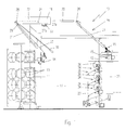
- a textile machine 10 for false twist texturing a yarn 11 comprises a creel 11, a main frame 12, a first feed device 14, a second feed device 15, a false twist device 16, an operator's aisle 17 between the creel 11 and the main frame 12, a first heater 18 and a cooling zone 19 in which there are cooling plates 20, 21.
- a yarn 23 is fed from a supply package 13 mounted in the creel 11, in sequence through the first feed device 14, the first heater 18, the cooling zone 19, the false twist device 16 and an optional second heater 33 to a take-up package 36 mounted in a cradle 34 in the take-up zone 35.
- a yarn guide 28 mounted on a sledge 29 that is movable along a track 31 by means of a rod 30 from a threading position adjacent the first feed device 14 to a processing position adjacent the end 32 of the heater 18.
- the yarn 23 runs in a substantially straight line from the first feed device 14 to the guide 26 between the cooling plates 20, 21, out of contact with the heater 18 and cooling plate 20.
- the yarn 23 runs over various surfaces of the textile machine 10, for example the feed devices 14, 15, the cooling plates 20, 21, the false twist device 16 and the yarn guides 28, 26.
- the yarn may run in contact with the surfaces of the heaters 18, 33. This can cause deposits of yarn debris to accumulate on those surfaces.
- the supply yarn 23 invariably has yarn processing oil on it, deposits of the oil may accumulate on some of the surfaces, in particular that of the heater 18. In order that the quality of the processed yarn is not to deteriorate to an unacceptable level, it is necessary to clean the abovementioned surfaces from time to time. Conventionally this is done by brushing by hand, using various cleaning substances such as detergents.
- the cleaning device 22 comprises a laser beam generating device 27a operable to direct a laser beam from outside the heater 18 through the structure of the heater 18 in a direction substantially perpendicular to the surface 24 in contact with or adjacent which the yarn 23 runs when being processed.
- the cleaning device 22 is movable longitudinally of the heater 18 in order that the whole of the surface 24 may be cleaned.
- the beam is directed upwardly away from the operator's aisle 17, thereby avoiding any risk to an operator.
- the laser beam is formed by the generator 27a and a lens arrangement 27b to be substantially parallel, and may be a CO 2 , Nd:YAG or Excimer laser.
- the beam may have a wavelength chosen to suit the material of the surface 24 and/or the material to be removed from that surface, and may be in the region of 1.064 ⁇ m or 0.532 ⁇ m.
- the beam is pulsed with a pulse duration of between 5 and 30 nSec.
- the number of pulses is between 5 and 120 per second, and the average power is between 5 and 25 W.
- the effect of the beam is to turn the outer layers of the deposited material on the surface 24 into a plasma and create vibrationary shock waves through the deposit, which are reflected by the surface 24 and interfere with the next pulse to break up the deposit so that it falls away from the surface 24.
- the heater 18 may be cleaned with the yarn 23 still running, thereby reducing machine down-time to zero. If this is not possible, this cleaning process may be performed with the yarn 23 moved out of contact with the heater 18 and cooling plate 20 by lowering the sledge 29. However, the heater 18 can still be at an elevated temperature and preferably at its operating temperature. By this means the overall down time of the machine 10 is considerably reduced by comparison with currently used cleaning methods.
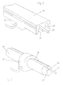
- a substitute surface 24' may be provided as shown in Fig. 2. In this case the heater 18 has two heating surfaces 24, 24', which run parallel with each other longitudinally of the heater 18 and both of which are at the operating temperature.
- the yarn 23 is shown running in contact with the surface 24.
- the yarn 23 is rapidly transferred to run in contact with the substitute surface 24' until such time as the reverse transfer is required. In this way machine down time is avoided.
- the heater may be cleaned whilst at operating temperature, the yarn may be left running in contact with the surface 24, but run to waste if its quality is unacceptable due to the cleaning process.
- FIG. 3 An alternative embodiment of heater 18 for the same purpose as that shown in Fig. 2 is shown in Fig. 3.
- the substitute surface 24' is disposed diametrically opposite to the surface 24.
- the heater 18 is rotated about its longitudinal axis 25 and the yarn 23 transferred from surface 24 to surface 24'. All of the above comments in relation to constructional arrangements of the cleaning device 22 and the heater 18 apply to the heater 33 the cooling plates 20, 21.
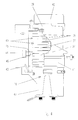
- a false twisting device 16 which is mounted in the textile machine 10 by means of a base 47.
- the false twisting device 16 comprises three parallel spindles 37 on which are mounted the twisting discs 38.
- the yarn 23 runs over the peripheral surfaces 40 of the discs 38, which become glazed as the troughs in the surfaces 40 become filled with yarn debris.
- the discs 38 are changed on the device 16, or the device as a whole is changed. In either case costly machine down time is involved.
- a cleaning device 22 is secured to the base 47 and top 39 of the device 16, and is positioned so as to direct the laser beam at the surfaces 40 of the discs 38 to clean them whilst running.
- the laser beam generator 44 is movable vertically in order that each of the surfaces 40 may be cleaned in turn.
- a fibre optic cable 45 extends near to the surface 40 being cleaned so as to accurately direct the laser beam at the surface 40.
- the twisting device 16 is enclosed in a casing 41 (shown partly cut away ) and cap 42 so as to reduce the risk to an operator from use of the laser cleaning device 22.
- the cleaning device 22 cannot operate unless it is secured to the machine 10 and the electrical supply is connected by cable 43. This reduces the risk of misuse of the cleaning device 22.
- a jet of air is directed at the end of the fibre optic cable 45 by a blowing device 46.
Landscapes
- Engineering & Computer Science (AREA)
- Textile Engineering (AREA)
- Mechanical Engineering (AREA)
- Yarns And Mechanical Finishing Of Yarns Or Ropes (AREA)
- Cleaning In General (AREA)
- Spinning Or Twisting Of Yarns (AREA)
Applications Claiming Priority (2)
| Application Number | Priority Date | Filing Date | Title |
|---|---|---|---|
| GBGB9700432.9A GB9700432D0 (en) | 1997-01-10 | 1997-01-10 | Cleaning textile machines |
| GB9700432 | 1997-01-10 |
Publications (2)
| Publication Number | Publication Date |
|---|---|
| EP0853148A2 true EP0853148A2 (de) | 1998-07-15 |
| EP0853148A3 EP0853148A3 (de) | 1999-03-31 |
Family
ID=10805781
Family Applications (1)
| Application Number | Title | Priority Date | Filing Date |
|---|---|---|---|
| EP98300065A Withdrawn EP0853148A3 (de) | 1997-01-10 | 1998-01-07 | Reinigung von Textilmaschinen |
Country Status (4)
| Country | Link |
|---|---|
| US (1) | US6004398A (de) |
| EP (1) | EP0853148A3 (de) |
| JP (1) | JPH10212636A (de) |
| GB (1) | GB9700432D0 (de) |
Cited By (1)
| Publication number | Priority date | Publication date | Assignee | Title |
|---|---|---|---|---|
| CN111977458A (zh) * | 2020-09-28 | 2020-11-24 | 来一萍 | 一种电力施工用具有表面清洁功能的光纤收卷设备 |
Families Citing this family (4)
| Publication number | Priority date | Publication date | Assignee | Title |
|---|---|---|---|---|
| US6710285B2 (en) | 2002-06-01 | 2004-03-23 | First Call Explosive Solutions, Inc. | Laser system for slag removal |
| CN111112168A (zh) * | 2020-01-06 | 2020-05-08 | 唐红英 | 一种纺织用除尘装置 |
| CN113502576B (zh) * | 2021-08-17 | 2022-08-02 | 安徽东锦资源再生科技有限公司 | 再生聚酯短纤的环保型卷曲装置及其方法 |
| CN115156169B (zh) * | 2022-07-06 | 2023-07-28 | 杭州临港化纤有限公司 | 一种假捻盘的清洗工艺 |
Family Cites Families (9)
| Publication number | Priority date | Publication date | Assignee | Title |
|---|---|---|---|---|
| CH471915A (de) * | 1967-03-28 | 1969-06-13 | Eldima Ag | Verfahren zum Kräuseln von verstreckten, mindestens teilweise aus thermoplastischem Material bestehenden Textilfäden und Fadenbündeln |
| US4292770A (en) * | 1980-03-17 | 1981-10-06 | Ansley, Incorporated | Yarn heater track cleaning apparatus and method |
| JPS63300276A (ja) * | 1987-05-29 | 1988-12-07 | Ricoh Co Ltd | レ−ザプリンタ、複写機等のクリ−ニング装置 |
| JPH0497776A (ja) * | 1990-08-17 | 1992-03-30 | Seki:Kk | ミシン用ボビンの製造方法 |
| US5262617A (en) * | 1990-08-17 | 1993-11-16 | Kabushiki Kaisha Tokyo Horaisha | Cutting means for fabrics and the like utilizing a heated cutting means mounted on a movable carriage |
| DE4125500A1 (de) * | 1991-08-01 | 1993-02-04 | Reinhardt Thyzel | Verfahren zum bearbeiten und insbesondere zum markieren von oberflaechen |
| DE4241575A1 (de) * | 1992-12-10 | 1994-06-16 | Baldwin Gegenheimer Gmbh | Verfahren und Vorrichtung zum kontaktfreien Entfernen von Schmutz von Gegenständen, insbesondere von Druckmaschinen-Zylindern |
| US5367141A (en) * | 1993-03-26 | 1994-11-22 | The United States Of America As Represented By The United States Department Of Energy | Photochemical cutting of fabrics |
| US5881886A (en) * | 1994-03-18 | 1999-03-16 | Brown University Research Foundation | Optically-based methods and apparatus for sorting garments and other textiles |
-
1997
- 1997-01-10 GB GBGB9700432.9A patent/GB9700432D0/en active Pending
- 1997-12-31 US US09/002,035 patent/US6004398A/en not_active Expired - Fee Related
-
1998
- 1998-01-05 JP JP10011924A patent/JPH10212636A/ja active Pending
- 1998-01-07 EP EP98300065A patent/EP0853148A3/de not_active Withdrawn
Cited By (1)
| Publication number | Priority date | Publication date | Assignee | Title |
|---|---|---|---|---|
| CN111977458A (zh) * | 2020-09-28 | 2020-11-24 | 来一萍 | 一种电力施工用具有表面清洁功能的光纤收卷设备 |
Also Published As
| Publication number | Publication date |
|---|---|
| US6004398A (en) | 1999-12-21 |
| JPH10212636A (ja) | 1998-08-11 |
| GB9700432D0 (en) | 1997-02-26 |
| EP0853148A3 (de) | 1999-03-31 |
Similar Documents
| Publication | Publication Date | Title |
|---|---|---|
| JP5508395B2 (ja) | ワイヤーソー装置およびそれを操作するための方法 | |
| KR102033741B1 (ko) | 이형제 스프레이 모듈의 세척장치 | |
| KR102599764B1 (ko) | 와이어 본딩 툴을 위한 클리닝 시스템, 이러한 시스템을 포함하는 와이어 본딩 기계, 및 관련 방법 | |
| CN101537413B (zh) | 用于维护和/或清洁工件支撑部件的支撑条带的机械装置 | |
| KR20190025654A (ko) | 계획되지 않은 중단 후에 공작물의 와이어 소잉 프로세스를 재개하기 위한 방법 및 장치 | |
| US6004398A (en) | Cleaning textile machines | |
| JP2000015626A (ja) | 切削装置 | |
| US6261166B1 (en) | Wire cleaning apparatus | |
| CN110733932B (zh) | 一种熔体纺丝和卷绕纱线的方法 | |
| US4536632A (en) | Wire-cut electroerosion method and apparatus utilizing wire-cleaning means | |
| KR19990012559U (ko) | 철제롤용 이물자동제거장치 | |
| JP7143411B2 (ja) | 溶融紡糸装置 | |
| JP4777072B2 (ja) | ダイシング装置 | |
| JP2004531773A (ja) | 単一ステップファイバ加工装置 | |
| JPH02160939A (ja) | リング精紡機或いはリング撚糸機における自動ボビン交換装置においてチューブおよびボビンの把持および解放を監視する方法および装置 | |
| TWI909257B (zh) | 清潔玻璃製造設備的方法及製造玻璃帶的方法 | |
| FR2482498B1 (fr) | Procede et dispositif pour remettre automatiquement en place un fil electrode sur une machine d'electroerosion | |
| KR102035064B1 (ko) | 와이어 방전가공기용 세척 장치 | |
| CN218610799U (zh) | 激光工件清洗系统 | |
| JPH08336829A (ja) | ワイヤソー | |
| CN101448606B (zh) | 用于清洁机床的工件支撑件的至少一个支撑元件的方法 | |
| US20230228007A1 (en) | Method for operating a spinning station of a rotor spinning machine and rotor spinning machine | |
| CN117463656A (zh) | 一种使用游离磨料进行切割的金属线在线修复方法 | |
| CN221028697U (zh) | 一种螺纹钢除锈工具 | |
| JP2931245B2 (ja) | 残糸カッティング装置 |
Legal Events
| Date | Code | Title | Description |
|---|---|---|---|
| PUAI | Public reference made under article 153(3) epc to a published international application that has entered the european phase |
Free format text: ORIGINAL CODE: 0009012 |
|
| AK | Designated contracting states |
Kind code of ref document: A2 Designated state(s): CH DE FR GB IT LI |
|
| AX | Request for extension of the european patent |
Free format text: AL;LT;LV;MK;RO;SI |
|
| PUAL | Search report despatched |
Free format text: ORIGINAL CODE: 0009013 |
|
| AK | Designated contracting states |
Kind code of ref document: A3 Designated state(s): AT BE CH DE DK ES FI FR GB GR IE IT LI LU MC NL PT SE |
|
| AX | Request for extension of the european patent |
Free format text: AL;LT;LV;MK;RO;SI |
|
| 17P | Request for examination filed |
Effective date: 19990714 |
|
| AKX | Designation fees paid |
Free format text: CH DE FR GB IT LI |
|
| 17Q | First examination report despatched |
Effective date: 20001012 |
|
| STAA | Information on the status of an ep patent application or granted ep patent |
Free format text: STATUS: THE APPLICATION IS DEEMED TO BE WITHDRAWN |
|
| 18D | Application deemed to be withdrawn |
Effective date: 20010424 |