EP0853178A1 - Befestigungselement für metallische Profilschiene - Google Patents
Befestigungselement für metallische Profilschiene Download PDFInfo
- Publication number
- EP0853178A1 EP0853178A1 EP98100263A EP98100263A EP0853178A1 EP 0853178 A1 EP0853178 A1 EP 0853178A1 EP 98100263 A EP98100263 A EP 98100263A EP 98100263 A EP98100263 A EP 98100263A EP 0853178 A1 EP0853178 A1 EP 0853178A1
- Authority
- EP
- European Patent Office
- Prior art keywords
- fastening element
- section bar
- accessory
- grooves
- pair
- Prior art date
- Legal status (The legal status is an assumption and is not a legal conclusion. Google has not performed a legal analysis and makes no representation as to the accuracy of the status listed.)
- Withdrawn
Links
- 239000002184 metal Substances 0.000 title claims abstract description 13
- 238000000465 moulding Methods 0.000 claims abstract description 14
- 230000004069 differentiation Effects 0.000 description 1
- 238000003780 insertion Methods 0.000 description 1
- 230000037431 insertion Effects 0.000 description 1
- 238000009434 installation Methods 0.000 description 1
- 238000012986 modification Methods 0.000 description 1
- 230000004048 modification Effects 0.000 description 1
- 230000000750 progressive effect Effects 0.000 description 1
Images

Classifications
-
- E—FIXED CONSTRUCTIONS
- E05—LOCKS; KEYS; WINDOW OR DOOR FITTINGS; SAFES
- E05D—HINGES OR SUSPENSION DEVICES FOR DOORS, WINDOWS OR WINGS
- E05D5/00—Construction of single parts, e.g. the parts for attachment
- E05D5/02—Parts for attachment, e.g. flaps
- E05D5/0215—Parts for attachment, e.g. flaps for attachment to profile members or the like
- E05D5/0223—Parts for attachment, e.g. flaps for attachment to profile members or the like with parts, e.g. screws, extending through the profile wall or engaging profile grooves
- E05D5/0238—Parts for attachment, e.g. flaps for attachment to profile members or the like with parts, e.g. screws, extending through the profile wall or engaging profile grooves with parts engaging profile grooves
-
- F—MECHANICAL ENGINEERING; LIGHTING; HEATING; WEAPONS; BLASTING
- F16—ENGINEERING ELEMENTS AND UNITS; GENERAL MEASURES FOR PRODUCING AND MAINTAINING EFFECTIVE FUNCTIONING OF MACHINES OR INSTALLATIONS; THERMAL INSULATION IN GENERAL
- F16B—DEVICES FOR FASTENING OR SECURING CONSTRUCTIONAL ELEMENTS OR MACHINE PARTS TOGETHER, e.g. NAILS, BOLTS, CIRCLIPS, CLAMPS, CLIPS OR WEDGES; JOINTS OR JOINTING
- F16B7/00—Connections of rods or tubes, e.g. of non-circular section, mutually, including resilient connections
- F16B7/22—Connections of rods or tubes, e.g. of non-circular section, mutually, including resilient connections using hooks or like elements
-
- F—MECHANICAL ENGINEERING; LIGHTING; HEATING; WEAPONS; BLASTING
- F16—ENGINEERING ELEMENTS AND UNITS; GENERAL MEASURES FOR PRODUCING AND MAINTAINING EFFECTIVE FUNCTIONING OF MACHINES OR INSTALLATIONS; THERMAL INSULATION IN GENERAL
- F16B—DEVICES FOR FASTENING OR SECURING CONSTRUCTIONAL ELEMENTS OR MACHINE PARTS TOGETHER, e.g. NAILS, BOLTS, CIRCLIPS, CLAMPS, CLIPS OR WEDGES; JOINTS OR JOINTING
- F16B2200/00—Constructional details of connections not covered for in other groups of this subclass
- F16B2200/20—Connections with hook-like parts gripping behind a blind side of an element to be connected
- F16B2200/205—Connections with hook-like parts gripping behind a blind side of an element to be connected the hook being a separate retainer
-
- F—MECHANICAL ENGINEERING; LIGHTING; HEATING; WEAPONS; BLASTING
- F16—ENGINEERING ELEMENTS AND UNITS; GENERAL MEASURES FOR PRODUCING AND MAINTAINING EFFECTIVE FUNCTIONING OF MACHINES OR INSTALLATIONS; THERMAL INSULATION IN GENERAL
- F16B—DEVICES FOR FASTENING OR SECURING CONSTRUCTIONAL ELEMENTS OR MACHINE PARTS TOGETHER, e.g. NAILS, BOLTS, CIRCLIPS, CLAMPS, CLIPS OR WEDGES; JOINTS OR JOINTING
- F16B7/00—Connections of rods or tubes, e.g. of non-circular section, mutually, including resilient connections
- F16B7/04—Clamping or clipping connections
- F16B7/0433—Clamping or clipping connections for rods or tubes being in parallel relationship
Definitions
- the present invention relates to a fastening element for metal casings usable to secure to metal section bars of casings those accessories or components such as, for instance, the hinges which define the articulated connection between fixed frame and movable frame.
- the present invention aims at solving the problem related to associating components onto metal section bars of particular conformation.
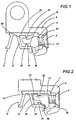
- a possible non limiting example of utilisation of the subject fastening element can be constituted by the section bar shown in Figure 3, where it is shown in a transverse section to the direction of development.
- the section bar presents, for its own structural characteristics, an inner chamber 37 delimited, at the ends, by inclined shoulders 31. This particular conformation determines a consequent differentiation at least of the parts closely connected (i.e. partially coinciding) with the inner chamber. Among them, also the throats generally used to fasten components to the window or door.
- throats are constituted by pairs of parallel mouldings or cornices, presented by the metal section bars, and provided with mutually projecting fins; such mouldings or cornices constitute in practice a sort of groove with an essentially "C" shaped cross section, whose smaller sides are represented by “L” shaped portions symmetrically opposed and the greater side perpendicular to the smaller sides so as to define a cavity with rectangular cross section.
- the throat is generally constituted by a "C" shaped grooved with rectangular cross section.
- the solution conventionally used in most recent times provides for the use of a fastening element or tab insertable into the aforesaid throat and able to be associated by means of screws to an accessory, for example a hinge.
- the progressive mutual approach oftab and hinge due to screwing makes the tab slide along appropriate guide surfaces presented by the hinge, so as to cause respectively a longitudinal portion of the tab and a base portion of the hinge to be inserted into the two "L" shaped portions of the throat.
- the throat 30 presented by the section bar 3 comprises a groove shaped according to a sort of oblique letter "C", wherein the bottom wall (in practice corresponding to the longer side of the "C" in the drawing) coincides with one of the aforesaid inclined shoulders 31 and is not perpendicular with respect to the side walls, determining a groove which, in its cross section, defines a sort of trapezoid.
- the essentially trapezoidal conformation of the groove prevents prior art fastening elements (or tabs) from being inserted correctly and from adequately securing the components.
- the invention solves the problem of providing a fastening element for metal casings wherein housing in an essentially trapezoidal groove is provided for, i.e. wherein the distance between the bottom wall and one of the fins that delimit the groove has a relatively modest value.
- the fastening element can be pre-mounted on the accessory or hinge, in order to allow for considerable time savings when mounting the window or door.
- the fastening element 1 for metal casings is of the type usable to secure an accessory or component 2 to a metal section bar of the casing itself.
- the section bar 3 presents a profile wherein the throat 30 destined to house the tab or fastening element 1 presents, in cross section, a conformation essentially as an oblique "C", meaning by that term a trapezoidal section wherein the bottom wall 31 of the throat 30 is not perpendicular to the side walls.
- the seat 30 with longitudinal development is defined by a bottom wall 31, a pair of side walls 32 and 33 opposing each other and two parallel opposed mouldings or cornices 34 and 35.
- a first side wall 32 of the pair of side walls 32 and 33 therefore extends for a value greater than that of the other side wall 33.
- screw means 4 or the like are provided.
- the fastening element 1 presents a base portion 11 destined to oppose the accessory 2 and a latching portion 12, opposite to the base portion 11 and suitable for fastening to section bar 3.
- the latching portion 12 in its free end, has a curved shape, and is oriented towards a first side in order to define a tooth with longitudinal development 13 (meaning as longitudinal the development of the element 1 itself).
- the latching portion 12 presents a pair of grooves 14 and 15; in this way it is possible, once the fastening element 1 is associated loosely to the accessory 2, to introduce the tooth 13 into the seat 30, thanks to the play allowed by the grooves 14 and 15 with respect to the projections presented by the section bar 3.
- the association between accessory 2 and element 1 can be executed before the mounting phase, in order to offer a tab-hinge set already composed.
- section bar 3 presents, externally to a first one (34) of the mouldings or cornices, an angular portion 36.
- a first one (15) of the grooves 14 and 15 extends for a value substantially corresponding to the height ofthe first moulding or cornice 34 and the distance between the two grooves 14 and 15 is substantially equal to the value of the distance between the first moulding or cornice 34 and the angular portion 36: in this way it is possible for the fastening element 1, once associated to the section bar 3, to be able to copy the profile portion defined by the first cornice or moulding 34 and by the angle portion 36.
- Figure 2 shows, with a dashed line, a possible positioning of the element 1 during mounting to a section bar 3; in this position, the element 1 is associated to the accessory 2, but presents a certain freedom which allows the introduction of the tooth 13 inside the throat 30, so as to define, after screw means 4 have been screwed, an attachment with the moulding 35. Screwing the means 4 causes the accessory 2 to move closer to section bar 3 (which position is not shown in the Figure), with an insertion of the element 1, in particular of the base portion 11, inside the cavity 20 presented by the accessory 2 itself.
- the fastening element 1 is provided, at its ends, with a pair of projecting appendices or wings 16, defining, with the longitudinal development of the fastening element 1 essentially right angles; in this way a means for manually gripping the fastening element 1 is defined, along with a means for obtaining a squared positioning of the element itself.
Landscapes
- Engineering & Computer Science (AREA)
- Mechanical Engineering (AREA)
- General Engineering & Computer Science (AREA)
- Manufacture Of Alloys Or Alloy Compounds (AREA)
- Superconductors And Manufacturing Methods Therefor (AREA)
- Clamps And Clips (AREA)
Applications Claiming Priority (2)
| Application Number | Priority Date | Filing Date | Title |
|---|---|---|---|
| IT97BO000006A IT1290631B1 (it) | 1997-01-09 | 1997-01-09 | Elemento di ancoraggio per profilati metallici. |
| ITBO970006 | 1997-01-09 |
Publications (1)
| Publication Number | Publication Date |
|---|---|
| EP0853178A1 true EP0853178A1 (de) | 1998-07-15 |
Family
ID=11341827
Family Applications (1)
| Application Number | Title | Priority Date | Filing Date |
|---|---|---|---|
| EP98100263A Withdrawn EP0853178A1 (de) | 1997-01-09 | 1998-01-09 | Befestigungselement für metallische Profilschiene |
Country Status (2)
| Country | Link |
|---|---|
| EP (1) | EP0853178A1 (de) |
| IT (1) | IT1290631B1 (de) |
Cited By (1)
| Publication number | Priority date | Publication date | Assignee | Title |
|---|---|---|---|---|
| EP2248975A1 (de) * | 2009-05-07 | 2010-11-10 | van Parys, Remi Emiel | Klemmanker zur Befestigung von Beschlägen an einem Hohlprofil eines Fensters oder einer Tür |
Citations (2)
| Publication number | Priority date | Publication date | Assignee | Title |
|---|---|---|---|---|
| DE9113522U1 (de) * | 1991-10-30 | 1991-12-19 | Ferco International, Sarrebourg | Beschlag zur Befestigung in einer beidseitig hinterschnittenen Profilnut |
| EP0659967A2 (de) * | 1993-12-22 | 1995-06-28 | ERRETI S.r.l. | Verankerungselement für Metallarmaturen |
-
1997
- 1997-01-09 IT IT97BO000006A patent/IT1290631B1/it active IP Right Grant
-
1998
- 1998-01-09 EP EP98100263A patent/EP0853178A1/de not_active Withdrawn
Patent Citations (2)
| Publication number | Priority date | Publication date | Assignee | Title |
|---|---|---|---|---|
| DE9113522U1 (de) * | 1991-10-30 | 1991-12-19 | Ferco International, Sarrebourg | Beschlag zur Befestigung in einer beidseitig hinterschnittenen Profilnut |
| EP0659967A2 (de) * | 1993-12-22 | 1995-06-28 | ERRETI S.r.l. | Verankerungselement für Metallarmaturen |
Cited By (2)
| Publication number | Priority date | Publication date | Assignee | Title |
|---|---|---|---|---|
| EP2248975A1 (de) * | 2009-05-07 | 2010-11-10 | van Parys, Remi Emiel | Klemmanker zur Befestigung von Beschlägen an einem Hohlprofil eines Fensters oder einer Tür |
| BE1018747A3 (nl) * | 2009-05-07 | 2011-08-02 | Parys Remi E Van | Klemanker voor bevestiging van een beslag op een hol profiel van een raam of deur. |
Also Published As
| Publication number | Publication date |
|---|---|
| IT1290631B1 (it) | 1998-12-10 |
| ITBO970006A0 (it) | 1997-01-09 |
| ITBO970006A1 (it) | 1998-07-09 |
| ITBO970006A3 (it) | 1998-07-09 |
Similar Documents
| Publication | Publication Date | Title |
|---|---|---|
| US8789900B2 (en) | Door for a household appliance | |
| CA2390970C (en) | Hanger bar assembly | |
| US6138325A (en) | Mounting device for a window hinge | |
| US6205615B1 (en) | Door closer | |
| EP1389661A2 (de) | Scharnier | |
| US3952366A (en) | Hinge device | |
| EP0487127B1 (de) | Wandaufbau, mit Wandbestandteilen befestigt an einen Rahmen mittels nicht-sichtbaren Verbindungen | |
| EP0504115B1 (de) | Ein Scharnier für metallene Tür- und Fensterbeschläge | |
| EP0853178A1 (de) | Befestigungselement für metallische Profilschiene | |
| EP2093362B1 (de) | Verfahren und Klemmsystem zur Befestigung eines Scharniers oder anderen Beschlags an Profilen für Fenster und Türen | |
| HU220352B (hu) | Ajtó, ablak vagy hasonló nyílászáró szerkezet vasalati szerkezeti eleme, nevezetesen egy ütköző, amely alkalmas alumínium- vagy PVC-profilra való felszerelésre | |
| EP0599846A1 (de) | Kupplung für tür- oder fensterverbundprofile. | |
| RU2254430C1 (ru) | Крепление фурнитуры | |
| JPS62164978A (ja) | 家具のヒンジ | |
| CN223151874U (zh) | 滑轮组件及推拉门窗 | |
| KR200279187Y1 (ko) | 새시 프레임 연결구조 | |
| KR20180009976A (ko) | 샤워 부스용 도어 | |
| GB2092660A (en) | Adjustable Hinge | |
| CN214740771U (zh) | 组合式窗户型材 | |
| KR860002665Y1 (ko) | 창호 레일 | |
| KR200377241Y1 (ko) | 착탈식 보조창틀이 구비된 창틀 | |
| KR200224345Y1 (ko) | 문틀의 고정장치 | |
| CN209353914U (zh) | 一种卡槽式内滑轨滑撑的固定结构 | |
| KR0119111Y1 (ko) | 알미늄 샤시 도어용 도어록 | |
| WO2001018926A1 (en) | Introductorty part of the description for mounting system |
Legal Events
| Date | Code | Title | Description |
|---|---|---|---|
| PUAI | Public reference made under article 153(3) epc to a published international application that has entered the european phase |
Free format text: ORIGINAL CODE: 0009012 |
|
| AK | Designated contracting states |
Kind code of ref document: A1 Designated state(s): AT BE CH DE ES FR GB GR IT LI LU PT |
|
| AX | Request for extension of the european patent |
Free format text: AL;LT;LV;MK;RO;SI |
|
| 17P | Request for examination filed |
Effective date: 19981009 |
|
| AKX | Designation fees paid |
Free format text: AT BE CH DE ES FR GB GR IT LI LU PT |
|
| RBV | Designated contracting states (corrected) |
Designated state(s): AT BE CH DE ES FR GB GR IT LI LU PT |
|
| 17Q | First examination report despatched |
Effective date: 20010523 |
|
| GRAP | Despatch of communication of intention to grant a patent |
Free format text: ORIGINAL CODE: EPIDOSNIGR1 |
|
| STAA | Information on the status of an ep patent application or granted ep patent |
Free format text: STATUS: THE APPLICATION IS DEEMED TO BE WITHDRAWN |
|
| 18D | Application deemed to be withdrawn |
Effective date: 20040819 |