EP0853181B1 - Feuerschutztür - Google Patents
Feuerschutztür Download PDFInfo
- Publication number
- EP0853181B1 EP0853181B1 EP97119768A EP97119768A EP0853181B1 EP 0853181 B1 EP0853181 B1 EP 0853181B1 EP 97119768 A EP97119768 A EP 97119768A EP 97119768 A EP97119768 A EP 97119768A EP 0853181 B1 EP0853181 B1 EP 0853181B1
- Authority
- EP
- European Patent Office
- Prior art keywords
- door leaf
- frame
- door
- fire protection
- elements
- Prior art date
- Legal status (The legal status is an assumption and is not a legal conclusion. Google has not performed a legal analysis and makes no representation as to the accuracy of the status listed.)
- Expired - Lifetime
Links
- 238000009434 installation Methods 0.000 claims abstract description 5
- 230000037431 insertion Effects 0.000 claims 1
- 238000003780 insertion Methods 0.000 claims 1
- 238000003466 welding Methods 0.000 description 3
- 238000010276 construction Methods 0.000 description 2
- 238000007789 sealing Methods 0.000 description 2
- 230000002146 bilateral effect Effects 0.000 description 1
- 230000003313 weakening effect Effects 0.000 description 1
Images


Classifications
-
- E—FIXED CONSTRUCTIONS
- E06—DOORS, WINDOWS, SHUTTERS, OR ROLLER BLINDS IN GENERAL; LADDERS
- E06B—FIXED OR MOVABLE CLOSURES FOR OPENINGS IN BUILDINGS, VEHICLES, FENCES OR LIKE ENCLOSURES IN GENERAL, e.g. DOORS, WINDOWS, BLINDS, GATES
- E06B1/00—Border constructions of openings in walls, floors, or ceilings; Frames to be rigidly mounted in such openings
- E06B1/04—Frames for doors, windows, or the like to be fixed in openings
- E06B1/52—Frames specially adapted for doors
- E06B1/526—Frames specially adapted for doors for door wings that can be set up to open either left or right, outwards or inwards, e.g. provided with grooves for easily detachable hinges or latch plates
-
- E—FIXED CONSTRUCTIONS
- E06—DOORS, WINDOWS, SHUTTERS, OR ROLLER BLINDS IN GENERAL; LADDERS
- E06B—FIXED OR MOVABLE CLOSURES FOR OPENINGS IN BUILDINGS, VEHICLES, FENCES OR LIKE ENCLOSURES IN GENERAL, e.g. DOORS, WINDOWS, BLINDS, GATES
- E06B1/00—Border constructions of openings in walls, floors, or ceilings; Frames to be rigidly mounted in such openings
- E06B1/56—Fastening frames to the border of openings or to similar contiguous frames
- E06B1/60—Fastening frames to the border of openings or to similar contiguous frames by mechanical means, e.g. anchoring means
- E06B1/6092—Fastening door frames to the floor or ceiling; Jamb feet; Cross members uniting the jamb feet
Definitions
- the invention relates to a fire door consisting of a frame, which is designed as a full frame with opposite short and long frame parts, and a door leaf hinged to the frame by side hinges, which has a rollover on all four edges for optional installation for right / left hinging, wherein all frame parts have a Z-shaped cross-sectional profile of two right-angled frame parts connected by a web, the first frame part extending close to and parallel to the inside of the flap of the closed door in the direction of the wall, the second frame part parallel to the interior of the closed Door runs and the web is arranged parallel to the door leaf depth of the closed door.
- a fire protection door has already been proposed, the frame of which can be installed with a door leaf in the frame plane in positions rotated by 180 ° with respect to one another, the frame and the door leaf forming a unit which can be used for right and left hinging and which is completely 180 ° is rotatable.
- the generic fire protection door known from practice according to the preamble of claim 1 on the two opposite longitudinal sides to the inside of the door leaf has spaced-apart frame spar parts, each of which has angled ends in the direction of the door leaf, whereby a groove, for example for receiving sealing strips is formed.
- the two opposite short frame parts are each formed from two Z-shaped L-shaped angles, wherein the legs that form the web of the Z-shaped frame part are placed on top of one another and welded together.
- a fastening device is known from US Pat. No. 3,735,539 known for a threshold of a landing door.
- the device is installed before pouring the screed into the the threshold is to be integrated at the appropriate Position.
- the device has a trough trained housing, which subsequently with concrete is filled.
- the side walls of the housing have one Weakening to be able to change the height of the trough.
- the invention has for its object a fire door with the characteristics described above, whose short frame parts are made in such a way that they are suitable for the respective right or left stop on simple Can be prepared way, the lower one Frame part in the installed state then the complete Laying the screed is not significantly hindered and that upper frame part the possibility of the same tightness as the two long side frame parts allowed.
- This embodiment of the invention allows that in installed condition after demolition along the predetermined breaking point on the lower part of the frame nothing about the later floor level protrudes or runs parallel to it, so that the screed can be laid correctly is.
- the gap on the upper short frame part corresponds along the gap between the door leaf and frame the side frame parts and thus theirs Tightness.
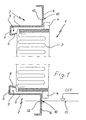
- a fire protection door 1 consists of a frame 2, which is designed as a full frame, which is not shown, and one door leaf 3 connected therewith by side hinges, the door leaf 3 for optional installation for right or left hinging on all four edges has a rollover 4.
- the frame 2 has a Z-shaped cross-sectional basic shape that surrounds the door leaf 3 on all sides each with frame parts 5, 6 angled at right angles and these connecting web 7, the web 7 each parallel to the depth of the door leaf 3, the frame member 6 on the one hand each parallel to the inside of the rollover 4 and the frame member 5, on the other hand, each parallel with a distance to the inside of the Door leaf 3 runs, this frame spar part 5 each in the direction of the door leaf 3 angled end 8 to form a groove 9 into which e.g. a sealing profile is used can be exhibited.
- the short frame parts of the frame 2 which are only shown in FIGS. 1 to 4, have each on the frame spar parts 6 running parallel to the rollover 4
- Predetermined breaking point 10 over its length, which in the installed state of the frame 2 on lower frame part is in each case at the level of the bottom 11, so that after breaking off of the frame part protruding beyond the base 11 is no longer above the base 11 protrudes so that e.g. perfect screed laying is possible. That along The frame part to be broken off 10 can be broken before or after installation the frame can be removed.
- long side frame parts do not have a predetermined breaking point.
- the predetermined breaking point 10 can, as shown in FIGS. 1 and 2, preferably in each case by Notches 12 provided on the inside of the frame rail parts 6 are formed.
- Fig. 3 shows a predetermined breaking point 10, which is formed in that the Zargenholmteil 6 consists of two butt-abutting parts, which means Welding 13 (spot and / or seam welding) are connected.
- the predetermined breaking point 10 is formed in that the frame spar part 6 each of two parts with angled inwards and against each other Ends 14, 15, which are connected on the inside by welding 16.
- a compensation profile 18 with a Height, which corresponds approximately to the rollover 4 is provided on the respective underside of the door leaf 3rd between rollover 4 and inner door surface 17.
- This compensation profile 18 can be glued, riveted, welded or clipped on.
Landscapes
- Engineering & Computer Science (AREA)
- Civil Engineering (AREA)
- Structural Engineering (AREA)
- Mechanical Engineering (AREA)
- Special Wing (AREA)
- Securing Of Glass Panes Or The Like (AREA)
- Laying Of Electric Cables Or Lines Outside (AREA)
- Thermal Insulation (AREA)
Description
einer Zarge, die als Vollumfassungszarge mit jeweils gegenüberliegenden kurzen und langen Zargenteilen ausgebildet ist, und
einem mit der Zarge durch seitliche Scharniere gelenkig verbundenen Türblatt, welches zwecks wahlweisem Einbau für Rechts/Links-Anschlag an allen vier Rändern einen Überschlag aufweist,
wobei alle Zargenteile ein Z-förmiges Querschnittsprofil aus zwei rechtwinklig abgewinkelten und durch einen Steg verbundenen Zargenholmteilen aufweisen, wobei das erste Zargenholmteil sich nahe am und parallel zum Inneren des Überschlags der geschlossenen Tür in Richtung Wand erstreckt, wobei das zweite Zargenholmteil parallel zum Inneren der geschlossenen Tür verläuft und wobei der Steg parallel zur Türblatttiefe der geschlossenen Tür angeordnet ist.
wobei die Schenkel, die den Steg des Z-förmigen Zargenteils bilden, aufeinander gelegt und miteinander verschweißt sind.
- Fig. 1
- eine erfindungsgemäße Feuerschutztür im Vertikalschnitt,
- Fig. 2
- eine Ausgestaltung der Sollbruchstelle im kurzen Zargenteil im Querschnitt,
- Fig. 3
- eine andere Ausgestaltung im Querschnitt,
- Fig. 4
- eine weitere Ausgestaltung im Querschnitt,
- Fig. 5
- eine Ausgestaltung eines Ausgleichsprofils im Schnitt des unteren Teils des Türblattes im eingebauten Zustand.
Claims (8)
- Feuerschutztür, bestehend aus
einer Zarge (2), die als Vollumfassungszarge mit jeweils gegenüberliegenden kurzen und langen Zargenteilen ausgebildet ist, und
einem mit der Zarge (2) durch seitliche Scharniere gelenkig verbundenen Türblatt (3), welches zwecks wahlweisem Einbau für Rechts/Links-Anschlag an allen vier Rändern einen Überschlag (4) aufweist,
wobei alle Zargenteile ein Z-förmiges Querschnittsprofil aus zwei rechtwinklig abgewinkelten und durch einen Steg (7) verbundenen Zargenholmteilen (5, 6) aufweisen, wobei das erste Zargenholmteil (6) sich nahe am und parallel zum Inneren des Überschlags (4) der geschlossenen Tür in Richtung Wand erstreckt, wobei das zweite Zargenholmteil (5) parallel zum Inneren der geschlossenen Tür verläuft und wobei der Steg (7) parallel zur Türblatttiefe der geschlossenen Tür angeordnet ist, dadurch gekenn-zeichnet, dass die zweiten Zargenholmteile (5) aller vier Zargenteile mit Abstand zu dem geschlossenen Türblatt angeordnet sind und ein zum Türblatt abgewinkeltes Ende (8) aufweisen, welches eine Aufnahmenut (9) für ein Dichtungsprofil bildet, und dass die ersten Zargenholmteile (6) der kurzen Zargenteile über ihre Länge jeweils eine Sollbruchstelle (10) aufweisen, wobei die Sollbruchstelle (10) des im eingebauten Zustand unteren Zargenteils auf der Höhe einer Bodenfläche liegt. - Feuerschutztür nach Anspruch 1, dadurch gekennzeichnet, dass die Sollbruchstellen (10) jeweils als an der Innenseite der zweiten Zargenholmteile (6) angeordnete Kerben (12) ausgebildet sind.
- Feuerschutztür nach Anspruch 1, dadurch gekennzeichnet, dass die zweiten Zargenholmteile (6) jeweils aus zwei stumpf gegeneinander stoßenden, miteinander verschweißten Teilen bestehen und die Schweißnähte die Sollbruchstellen (10) bilden.
- Feuerschutztür nach Anspruch 1, dadurch gekennzeichnet, dass die zweiten Zargenholmteile (6) jeweils aus zwei Teilen mit nach innen abgewinkelten und gegeneinander anliegenden, mittels einer Schweißnaht (16) oder Nieten miteinander verbundenen Enden (14, 15) bestehen und die Verbindungsstellen die Sollbruchstellen (10) bilden.
- Feuerschutztür nach einem der Ansprüche 1 bis 4, dadurch gekennzeichnet, dass an der jeweiligen Unterseite des Türblattes (3) zwischen Überschlag (4) und Türblattinnenfläche (17) ein Ausgleichsprofil (18) mit einer Höhe, die etwa dem Überschlag (4) entspricht, vorgesehen ist.
- Feuerschutztür nach Anspruch 5, dadurch gekennzeichnet, dass das Ausgleichsprofil (18) sich über die gesamte Tiefe des Türblattes (3) bis zum Überschlag (4) erstreckt.
- Feuerschutztür nach Anspruch 5, dadurch gekennzeichnet, dass das Ausgleichsprofil (18) sich nur über einen Teil der Türblatttiefe erstreckt.
- Feuerschutztür nach den Ansprüchen 5 bis 7, dadurch gekennzeichnet, dass das Ausgleichsprofil (18) angeklebt, angenietet, angeschweißt oder angeklipst ist.
Priority Applications (1)
| Application Number | Priority Date | Filing Date | Title |
|---|---|---|---|
| SI9730657T SI0853181T1 (en) | 1997-01-14 | 1997-11-12 | Fire door |
Applications Claiming Priority (2)
| Application Number | Priority Date | Filing Date | Title |
|---|---|---|---|
| DE19700973A DE19700973C1 (de) | 1997-01-14 | 1997-01-14 | Feuerschutztür |
| DE19700973 | 1997-01-14 |
Publications (2)
| Publication Number | Publication Date |
|---|---|
| EP0853181A1 EP0853181A1 (de) | 1998-07-15 |
| EP0853181B1 true EP0853181B1 (de) | 2004-04-07 |
Family
ID=7817319
Family Applications (1)
| Application Number | Title | Priority Date | Filing Date |
|---|---|---|---|
| EP97119768A Expired - Lifetime EP0853181B1 (de) | 1997-01-14 | 1997-11-12 | Feuerschutztür |
Country Status (13)
| Country | Link |
|---|---|
| EP (1) | EP0853181B1 (de) |
| AT (1) | ATE263895T1 (de) |
| BR (1) | BR9800012A (de) |
| CZ (1) | CZ296082B6 (de) |
| DE (2) | DE19700973C1 (de) |
| DK (1) | DK0853181T3 (de) |
| ES (1) | ES2219721T3 (de) |
| HU (1) | HU220918B1 (de) |
| MY (1) | MY124635A (de) |
| PL (1) | PL193401B1 (de) |
| PT (1) | PT853181E (de) |
| SI (1) | SI0853181T1 (de) |
| SK (1) | SK285351B6 (de) |
Families Citing this family (3)
| Publication number | Priority date | Publication date | Assignee | Title |
|---|---|---|---|---|
| DE19855241A1 (de) * | 1998-11-30 | 2000-05-31 | Huels Troisdorf | Verfahren zur Befestigung eines Blendrahmens mittels einer Montagezarge |
| DK200900822A (en) * | 2009-07-02 | 2011-01-03 | Jeld Wen Danmark As | Metallic frame for enclosing a door or a window |
| DE102024108017A1 (de) * | 2024-03-20 | 2025-09-25 | Herport Innenausbauelemente Gmbh & Co. Kg | Steckzargenbausatz und Verfahren zur Herstellung eines Steckzargenbausatzes |
Family Cites Families (14)
| Publication number | Priority date | Publication date | Assignee | Title |
|---|---|---|---|---|
| DE1434226A1 (de) * | 1960-12-03 | 1968-10-24 | August Hoermann & Sohn Kg | Aus Zarge und Tuerblatt bestehende Tuerkombination |
| DE1683419C3 (de) * | 1967-02-06 | 1974-09-12 | Fa. Gustav Riexinger, 7100 Heilbronn | Türzarge, die als geschlossener, vorfabrizierter Rechteckrahmen ausgebildet ist |
| DE1683611A1 (de) * | 1967-10-10 | 1971-02-11 | Stahl Schanz Frankurt Am Main | Tuerblatt fuer Stahlzargen |
| US3735539A (en) * | 1971-10-26 | 1973-05-29 | Dahltstrom Corp | Mounting assembly for elevator door sill |
| DE7729613U1 (de) * | 1977-09-24 | 1978-01-19 | Fa. Walter Teckentrup, 4830 Guetersloh | Feuerschutztor |
| DE2947509A1 (de) * | 1979-11-24 | 1981-05-27 | Podszuck Gmbh & Co Kg, 2300 Kiel | Tuer mit einem seitlich und oben ueberfaelzten und unten stumpfen tuerblatt |
| DE8206386U1 (de) * | 1982-03-08 | 1992-08-12 | Held, Richard, 5239 Kirburg | In einer zarge gehaltene thermisch isolierte tuer |
| DE3712584A1 (de) * | 1987-04-14 | 1988-11-03 | Sommer Metallbau Stahlbau Gmbh | Tuer |
| DE3807833A1 (de) * | 1988-03-10 | 1989-09-21 | Paul Schmitz Gmbh | Stahltuer |
| CH678210A5 (de) * | 1989-04-10 | 1991-08-15 | Geilinger Ag | |
| FR2720383B1 (fr) * | 1994-05-24 | 1996-07-12 | Realisations Metallurg | Porte d'ascenseur et son procédé de montage. |
| DE29507001U1 (de) * | 1995-04-26 | 1996-05-30 | Fa. Walter Teckentrup, 33415 Verl | Anordnung einer Wendetür mit Zargenrahmen und Türblatt |
| DE19617624A1 (de) * | 1996-05-02 | 1997-11-06 | Riexinger Tuerenwerke Gmbh | Feuerschutztür |
| DE29700542U1 (de) * | 1997-01-14 | 1997-02-20 | Novoferm GmbH, 46459 Rees | Feuerschutztür |
-
1997
- 1997-01-14 DE DE19700973A patent/DE19700973C1/de not_active Expired - Fee Related
- 1997-11-12 ES ES97119768T patent/ES2219721T3/es not_active Expired - Lifetime
- 1997-11-12 DK DK97119768T patent/DK0853181T3/da active
- 1997-11-12 DE DE59711495T patent/DE59711495D1/de not_active Expired - Lifetime
- 1997-11-12 PT PT97119768T patent/PT853181E/pt unknown
- 1997-11-12 EP EP97119768A patent/EP0853181B1/de not_active Expired - Lifetime
- 1997-11-12 SI SI9730657T patent/SI0853181T1/xx unknown
- 1997-11-12 AT AT97119768T patent/ATE263895T1/de not_active IP Right Cessation
-
1998
- 1998-01-13 SK SK48-98A patent/SK285351B6/sk unknown
- 1998-01-13 MY MYPI98000135A patent/MY124635A/en unknown
- 1998-01-13 HU HU9800048A patent/HU220918B1/hu not_active IP Right Cessation
- 1998-01-14 CZ CZ0011598A patent/CZ296082B6/cs not_active IP Right Cessation
- 1998-01-14 PL PL324280A patent/PL193401B1/pl unknown
- 1998-01-14 BR BR9800012A patent/BR9800012A/pt not_active Application Discontinuation
Also Published As
| Publication number | Publication date |
|---|---|
| DE59711495D1 (de) | 2004-05-13 |
| DE19700973C1 (de) | 1998-03-12 |
| HU220918B1 (en) | 2002-06-29 |
| CZ11598A3 (cs) | 1998-07-15 |
| HU9800048D0 (en) | 1998-03-30 |
| EP0853181A1 (de) | 1998-07-15 |
| SI0853181T1 (en) | 2004-10-31 |
| HUP9800048A2 (hu) | 1998-11-30 |
| ATE263895T1 (de) | 2004-04-15 |
| ES2219721T3 (es) | 2004-12-01 |
| PT853181E (pt) | 2004-08-31 |
| SK285351B6 (sk) | 2006-11-03 |
| SK4898A3 (en) | 1998-10-07 |
| BR9800012A (pt) | 1999-04-27 |
| PL193401B1 (pl) | 2007-02-28 |
| PL324280A1 (en) | 1998-07-20 |
| MY124635A (en) | 2006-06-30 |
| CZ296082B6 (cs) | 2006-01-11 |
| DK0853181T3 (da) | 2004-08-09 |
Similar Documents
| Publication | Publication Date | Title |
|---|---|---|
| EP3384568B1 (de) | Rahmenprofil für ein rahmengestell eines schaltschranks und ein entsprechendes rahmengestell | |
| EP0144955B2 (de) | Rahmengestell für einen Schaltschrank | |
| DE2811410A1 (de) | Formgeruest fuer ein gebaeude mit einer skelett- oder rahmenkonstruktion | |
| EP0345416B1 (de) | Nut-Federverbindung von Wand- oder Dachelementen | |
| DE1994725U (de) | Fugendichtungsleiste zur verwendung beim strassen- und brueckendeckenbau | |
| DE4445933B4 (de) | Mähdrescherkorntank | |
| DE3420897C2 (de) | Profilkombination zum Trennen von Putzflächen im Bereich waagerechter Fugen bei Bauwerken | |
| EP0745168B1 (de) | Ausfachsystem für wände und verkleidungen im bauwesen | |
| DE3504840A1 (de) | Versteifungsvorrichtung fuer einen stahlrohrmast | |
| EP0853181B1 (de) | Feuerschutztür | |
| DE102018101157A1 (de) | Schnellbauhalle, mit einer Eckverbindung zwischen Dach und Wand | |
| DE9305774U1 (de) | Fensterbank | |
| DE7825704U1 (de) | Im wesentlichen aus einem Metallhohlprofil bestehende Abstandshalterrahmen für Isolierglaseinheiten | |
| DE29700542U1 (de) | Feuerschutztür | |
| DE2800376A1 (de) | Liegendkufe fuer ein ausbaugestell einer untertaegigen mineralgewinnungsanlage | |
| DE2607307C2 (de) | Vorrichtung an sich überlappenden Ausbauprofilsegmenten des bogenförmigen Streckenausbaus im Berg- und Tunnelbau für die Vormontage der Baue | |
| DE19617624A1 (de) | Feuerschutztür | |
| DE3526227C1 (de) | Wassertrog | |
| DE10043544B4 (de) | Dichtungsstrang für einen Blendrahmen mit einem integrierten Flügelrahmen | |
| DE19618043C1 (de) | Unterkonstruktion zum Befestigen von Scharnierlappen an Zargen | |
| DE3149366C2 (de) | ||
| DE3732152A1 (de) | Verkleidung fuer rechteckige kamine | |
| AT403392B (de) | Verbindungskörper zum verbinden von zwei im wesentlichen u-förmigen rinnenelementen | |
| DE3818226C2 (de) | ||
| DE102020110043A1 (de) | Silo |
Legal Events
| Date | Code | Title | Description |
|---|---|---|---|
| PUAI | Public reference made under article 153(3) epc to a published international application that has entered the european phase |
Free format text: ORIGINAL CODE: 0009012 |
|
| AK | Designated contracting states |
Kind code of ref document: A1 Designated state(s): AT BE CH DE DK ES FR GB GR IT LI LU NL PT SE |
|
| AX | Request for extension of the european patent |
Free format text: AL;LT;LV;MK;RO;SI |
|
| 17P | Request for examination filed |
Effective date: 19980818 |
|
| AKX | Designation fees paid |
Free format text: AT BE CH DE DK ES FR GB GR IT LI LU NL PT SE |
|
| AXX | Extension fees paid |
Free format text: AL PAYMENT 990115;LT PAYMENT 990115;LV PAYMENT 990115;RO PAYMENT 990115;SI PAYMENT 990115 |
|
| RBV | Designated contracting states (corrected) |
Designated state(s): AT BE CH DE DK ES FR GB GR IT LI LU NL PT SE |
|
| 17Q | First examination report despatched |
Effective date: 20030219 |
|
| GRAP | Despatch of communication of intention to grant a patent |
Free format text: ORIGINAL CODE: EPIDOSNIGR1 |
|
| GRAS | Grant fee paid |
Free format text: ORIGINAL CODE: EPIDOSNIGR3 |
|
| GRAA | (expected) grant |
Free format text: ORIGINAL CODE: 0009210 |
|
| AK | Designated contracting states |
Kind code of ref document: B1 Designated state(s): AT BE CH DE DK ES FR GB GR IT LI LU NL PT SE |
|
| AX | Request for extension of the european patent |
Extension state: AL LT LV RO SI |
|
| REG | Reference to a national code |
Ref country code: GB Ref legal event code: FG4D Free format text: NOT ENGLISH |
|
| REG | Reference to a national code |
Ref country code: CH Ref legal event code: EP |
|
| REF | Corresponds to: |
Ref document number: 59711495 Country of ref document: DE Date of ref document: 20040513 Kind code of ref document: P |
|
| REG | Reference to a national code |
Ref country code: SE Ref legal event code: TRGR |
|
| REG | Reference to a national code |
Ref country code: CH Ref legal event code: NV Representative=s name: KELLER & PARTNER PATENTANWAELTE AG |
|
| REG | Reference to a national code |
Ref country code: DK Ref legal event code: T3 |
|
| GBT | Gb: translation of ep patent filed (gb section 77(6)(a)/1977) |
Effective date: 20040726 |
|
| REG | Reference to a national code |
Ref country code: GR Ref legal event code: EP Ref document number: 20040402419 Country of ref document: GR |
|
| REG | Reference to a national code |
Ref country code: PT Ref legal event code: SC4A Free format text: AVAILABILITY OF NATIONAL TRANSLATION Effective date: 20040702 |
|
| PG25 | Lapsed in a contracting state [announced via postgrant information from national office to epo] |
Ref country code: LU Free format text: LAPSE BECAUSE OF NON-PAYMENT OF DUE FEES Effective date: 20041112 |
|
| PG25 | Lapsed in a contracting state [announced via postgrant information from national office to epo] |
Ref country code: SE Free format text: LAPSE BECAUSE OF NON-PAYMENT OF DUE FEES Effective date: 20041113 |
|
| PG25 | Lapsed in a contracting state [announced via postgrant information from national office to epo] |
Ref country code: LI Free format text: LAPSE BECAUSE OF NON-PAYMENT OF DUE FEES Effective date: 20041130 Ref country code: DK Free format text: LAPSE BECAUSE OF NON-PAYMENT OF DUE FEES Effective date: 20041130 Ref country code: CH Free format text: LAPSE BECAUSE OF NON-PAYMENT OF DUE FEES Effective date: 20041130 |
|
| REG | Reference to a national code |
Ref country code: ES Ref legal event code: FG2A Ref document number: 2219721 Country of ref document: ES Kind code of ref document: T3 |
|
| ET | Fr: translation filed | ||
| REG | Reference to a national code |
Ref country code: SI Ref legal event code: IF |
|
| PLBQ | Unpublished change to opponent data |
Free format text: ORIGINAL CODE: EPIDOS OPPO |
|
| PLBI | Opposition filed |
Free format text: ORIGINAL CODE: 0009260 |
|
| PLAX | Notice of opposition and request to file observation + time limit sent |
Free format text: ORIGINAL CODE: EPIDOSNOBS2 |
|
| 26 | Opposition filed |
Opponent name: HOERMANN KG BRANDIS Effective date: 20050107 |
|
| NLR1 | Nl: opposition has been filed with the epo |
Opponent name: HOERMANN KG BRANDIS |
|
| PG25 | Lapsed in a contracting state [announced via postgrant information from national office to epo] |
Ref country code: GR Free format text: LAPSE BECAUSE OF NON-PAYMENT OF DUE FEES Effective date: 20050602 |
|
| PLBB | Reply of patent proprietor to notice(s) of opposition received |
Free format text: ORIGINAL CODE: EPIDOSNOBS3 |
|
| LTLA | Lt: lapse of european patent or patent extension |
Effective date: 20041112 |
|
| REG | Reference to a national code |
Ref country code: DK Ref legal event code: EBP |
|
| EUG | Se: european patent has lapsed | ||
| REG | Reference to a national code |
Ref country code: CH Ref legal event code: PL |
|
| PG25 | Lapsed in a contracting state [announced via postgrant information from national office to epo] |
Ref country code: PT Free format text: LAPSE BECAUSE OF NON-PAYMENT OF DUE FEES Effective date: 20050816 |
|
| REG | Reference to a national code |
Ref country code: PT Ref legal event code: MM4A Effective date: 20050816 |
|
| PLCK | Communication despatched that opposition was rejected |
Free format text: ORIGINAL CODE: EPIDOSNREJ1 |
|
| APAH | Appeal reference modified |
Free format text: ORIGINAL CODE: EPIDOSCREFNO |
|
| APBP | Date of receipt of notice of appeal recorded |
Free format text: ORIGINAL CODE: EPIDOSNNOA2O |
|
| APBQ | Date of receipt of statement of grounds of appeal recorded |
Free format text: ORIGINAL CODE: EPIDOSNNOA3O |
|
| PGFP | Annual fee paid to national office [announced via postgrant information from national office to epo] |
Ref country code: BE Payment date: 20071231 Year of fee payment: 11 |
|
| PG25 | Lapsed in a contracting state [announced via postgrant information from national office to epo] |
Ref country code: PT Free format text: LAPSE BECAUSE OF NON-PAYMENT OF DUE FEES Effective date: 20041112 |
|
| APBU | Appeal procedure closed |
Free format text: ORIGINAL CODE: EPIDOSNNOA9O |
|
| BERE | Be: lapsed |
Owner name: *NOVOFERM G.M.B.H. Effective date: 20081130 |
|
| PLBN | Opposition rejected |
Free format text: ORIGINAL CODE: 0009273 |
|
| STAA | Information on the status of an ep patent application or granted ep patent |
Free format text: STATUS: OPPOSITION REJECTED |
|
| 27O | Opposition rejected |
Effective date: 20090326 |
|
| PG25 | Lapsed in a contracting state [announced via postgrant information from national office to epo] |
Ref country code: BE Free format text: LAPSE BECAUSE OF NON-PAYMENT OF DUE FEES Effective date: 20081130 |
|
| NLR2 | Nl: decision of opposition |
Effective date: 20090326 |
|
| PGFP | Annual fee paid to national office [announced via postgrant information from national office to epo] |
Ref country code: ES Payment date: 20091123 Year of fee payment: 13 Ref country code: AT Payment date: 20091113 Year of fee payment: 13 |
|
| PGFP | Annual fee paid to national office [announced via postgrant information from national office to epo] |
Ref country code: NL Payment date: 20091112 Year of fee payment: 13 |
|
| PGFP | Annual fee paid to national office [announced via postgrant information from national office to epo] |
Ref country code: IT Payment date: 20091126 Year of fee payment: 13 |
|
| REG | Reference to a national code |
Ref country code: NL Ref legal event code: V1 Effective date: 20110601 |
|
| PG25 | Lapsed in a contracting state [announced via postgrant information from national office to epo] |
Ref country code: AT Free format text: LAPSE BECAUSE OF NON-PAYMENT OF DUE FEES Effective date: 20101112 Ref country code: NL Free format text: LAPSE BECAUSE OF NON-PAYMENT OF DUE FEES Effective date: 20110601 |
|
| REG | Reference to a national code |
Ref country code: SI Ref legal event code: KO00 Effective date: 20110728 |
|
| PG25 | Lapsed in a contracting state [announced via postgrant information from national office to epo] |
Ref country code: IT Free format text: LAPSE BECAUSE OF NON-PAYMENT OF DUE FEES Effective date: 20101112 |
|
| REG | Reference to a national code |
Ref country code: ES Ref legal event code: FD2A Effective date: 20120110 |
|
| PG25 | Lapsed in a contracting state [announced via postgrant information from national office to epo] |
Ref country code: ES Free format text: LAPSE BECAUSE OF NON-PAYMENT OF DUE FEES Effective date: 20101113 |
|
| PGFP | Annual fee paid to national office [announced via postgrant information from national office to epo] |
Ref country code: GB Payment date: 20141119 Year of fee payment: 18 Ref country code: FR Payment date: 20141119 Year of fee payment: 18 Ref country code: DE Payment date: 20141031 Year of fee payment: 18 |
|
| REG | Reference to a national code |
Ref country code: DE Ref legal event code: R119 Ref document number: 59711495 Country of ref document: DE |
|
| GBPC | Gb: european patent ceased through non-payment of renewal fee |
Effective date: 20151112 |
|
| REG | Reference to a national code |
Ref country code: FR Ref legal event code: ST Effective date: 20160729 |
|
| PG25 | Lapsed in a contracting state [announced via postgrant information from national office to epo] |
Ref country code: DE Free format text: LAPSE BECAUSE OF NON-PAYMENT OF DUE FEES Effective date: 20160601 Ref country code: GB Free format text: LAPSE BECAUSE OF NON-PAYMENT OF DUE FEES Effective date: 20151112 |
|
| PG25 | Lapsed in a contracting state [announced via postgrant information from national office to epo] |
Ref country code: FR Free format text: LAPSE BECAUSE OF NON-PAYMENT OF DUE FEES Effective date: 20151130 |