EP0853200A2 - Compresseur avec embrayage - Google Patents
Compresseur avec embrayage Download PDFInfo
- Publication number
- EP0853200A2 EP0853200A2 EP97310001A EP97310001A EP0853200A2 EP 0853200 A2 EP0853200 A2 EP 0853200A2 EP 97310001 A EP97310001 A EP 97310001A EP 97310001 A EP97310001 A EP 97310001A EP 0853200 A2 EP0853200 A2 EP 0853200A2
- Authority
- EP
- European Patent Office
- Prior art keywords
- housing
- compressor
- clutch
- gas compressor
- assembly
- Prior art date
- Legal status (The legal status is an assumption and is not a legal conclusion. Google has not performed a legal analysis and makes no representation as to the accuracy of the status listed.)
- Granted
Links
Images


Classifications
-
- F—MECHANICAL ENGINEERING; LIGHTING; HEATING; WEAPONS; BLASTING
- F04—POSITIVE - DISPLACEMENT MACHINES FOR LIQUIDS; PUMPS FOR LIQUIDS OR ELASTIC FLUIDS
- F04B—POSITIVE-DISPLACEMENT MACHINES FOR LIQUIDS; PUMPS
- F04B35/00—Piston pumps specially adapted for elastic fluids and characterised by the driving means to their working members, or by combination with, or adaptation to, specific driving engines or motors, not otherwise provided for
- F04B35/01—Piston pumps specially adapted for elastic fluids and characterised by the driving means to their working members, or by combination with, or adaptation to, specific driving engines or motors, not otherwise provided for the means being mechanical
-
- F—MECHANICAL ENGINEERING; LIGHTING; HEATING; WEAPONS; BLASTING
- F04—POSITIVE - DISPLACEMENT MACHINES FOR LIQUIDS; PUMPS FOR LIQUIDS OR ELASTIC FLUIDS
- F04B—POSITIVE-DISPLACEMENT MACHINES FOR LIQUIDS; PUMPS
- F04B35/00—Piston pumps specially adapted for elastic fluids and characterised by the driving means to their working members, or by combination with, or adaptation to, specific driving engines or motors, not otherwise provided for
- F04B35/002—Piston pumps specially adapted for elastic fluids and characterised by the driving means to their working members, or by combination with, or adaptation to, specific driving engines or motors, not otherwise provided for driven by internal combustion engines
-
- F—MECHANICAL ENGINEERING; LIGHTING; HEATING; WEAPONS; BLASTING
- F04—POSITIVE - DISPLACEMENT MACHINES FOR LIQUIDS; PUMPS FOR LIQUIDS OR ELASTIC FLUIDS
- F04B—POSITIVE-DISPLACEMENT MACHINES FOR LIQUIDS; PUMPS
- F04B49/00—Control, e.g. of pump delivery, or pump pressure of, or safety measures for, machines, pumps, or pumping installations, not otherwise provided for, or of interest apart from, groups F04B1/00 - F04B47/00
- F04B49/02—Stopping, starting, unloading or idling control
Definitions
- This invention relates to clutch-driven gas compressors especially but not exclusively a clutch-driven air compressor for use in automotive vehicles.
- the object of the present invention is to provide an improved clutch-driven compressor by which such space considerations are more easily accommodated.
- a gas compressor comprising a housing and a reciprocable wall said wall being movable in said housing to cyclicly increase and decrease the volume of a compression chamber to induce and deliver gas under pressure said wall being connected to an eccentric bearing of a shaft rotatable in a main bearing of the housing said shaft being drivable via a coupling means said coupling means being disengageable by an actuator to interrupt operation of the compressor characterised in that said actuator is located in a region of the housing surrounding said main bearing at least partially contained in a projection of said chamber in the direction of movement of said wall.
- said coupling means comprises a friction clutch.
- Said region may be provided in an assembly which serves also as a sole end cover of the compressor of an aperture via which the crank shaft may be assembled into the compressor crankcase end through which bearing the drive end of the shaft extends to couple with a drive-side of the clutch.
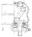
- the compressor housing 1 comprises an integral cast metal crank-case 2, two parallel cylinder bores 14 and 15 a clutch housing 4 enclosing a multiplate wet-clutch 12 which receives a drive end of a crank shaft 6.
- the details of the release clutch (12) and details of the cylinder head (not shown) are omitted from Fig. 1 in the interest of simplicity.
- the non-driven end bearing 5 of the crankshaft 6 is carried in an integral end plate 7 of the crank-case whereas the driven-end main bearing 8 is carried in a generally annular closure component 19, which is accessible for assembly purposes through the clutch housing 4.
- the aperture 20 which receives component 19 is of such external dimensions as to permit assembly of the crankshaft (6) into the crankcase 2 through aperture 20.
- Component 19 is then secured by a plurality of peripherally spaced bolts such as 22 before insertion of a multiplate clutch mechanism (not shown) of clutch 12.
- the annular closure component 19 and the bearing 8 carried thereby extend inwardly of the aperture 20 of the crankcase into an axial projection of the cylinder 14 and provide an axial abutment with the adjacent crank web 9. This and a corresponding inward projection 11 of the end 7 which carries the other main bearing 5 afford optimal use of the overall axial length of the crankcase housing.
- the annular closure component 19 is formed to provide an annular cylinder bore 23 surrounding and coaxial with bearing 8.
- An annular piston 24 has outer and inner annular seals 25 and 26 axially sealingly slideable in the annular bore 23.
- a thrust ring 27 carried by 24 is engageable with a release thrust bearing ring 28 of the clutch.
- the compressor main bearings 5 and 8 are supplied with oil under pressure from the vehicle engine via a further port 35 and oil-ways 36, 37, 38 breaking out at big-end crank pins 16 and 17 and at main bearings to provide the usual lubrication.
- a further oil-way (not shown) is provided to maintain oil irrigation of the plates in the present example of a multiplate wet-clutch.
- the cylinder head (not shown) conventionally has air inlet and delivery ports and respective reed-valves communicating with the compression chambers of the respective cylinders.
- the compressor operates in known manner whilst offering the energy saving to be expected from a governor-controlled clutch-driven compressor which only rotates when required to do so.
- a single housing drive-side end cover such as 19 which carries the annular release piston and according to the invention extends axially inwardly of the crankcase to utilise space in a projection of the cylinder bore 14, overall axial dimensions can be minimised.
- a screw-in control pressure port seal member 31 is seen to be provided in a control pressure port 30 in the crankcase housing to seal against assembly 19 and communicate with the interior of the annular clutch release cylinder 23 of the closure component 19 such that when pressurised by a control pressure from a governor device, the piston is urged leftwards as seen in Figs. 1 and 2 to act upon thrust ring 28 to release the friction clutch and unload the compressor.
- a spool seal 32 has two peripheral O-ring seals 33 and 34 and the component 19 is provided with a boss 19a of sufficient axial length to accommodate the innermost seal 33.
- the spool seal 32 is located in port 31 of the housing by a screw-in member 31a.
- the spool seal 32 is located at its inner end with a port 19b of a boss 19a which provides location with an axial recess 1b of the housing. The seal 32 is therefore able to tilt sufficiently to accommodate for only approximate alignment between 19a and 31a without leakage.
- a fluid tight communication between a screw-in port 41 may include a seal member 42 having a peripheral O-ring 43 which mutually seals with 41 and an end face sealing O-ring 44.
- the member 42 is urged by member 31 via a pair of disc-springs 45 into sealing engagement with a flat surface 19c of the component 19.
- the compressor is assembled by inserting the crankshaft (6) before closing the crankcase with the closure component 19 and securing same with the five spaced retaining bolts such as 22 inserted in respective tapped holes.
- Pistons with connecting rods are then lowered in the respective cylinder bores 14 and 15 for connection via connection rods (not shown) to crank pins 16 and 17 in a conventional manner employing access via respective cover plates 3a and 3b of the crankcase.
- the release clutch 12 is then installed to drivingly engage the drive-end of the crankshaft via splines or a key (not shown).
- the compressor described in the foregoing is flange-mounted to an internal combustion engine of a motor vehicle and operates in known manner to supply compressed air to one or more reservoirs of a vehicle braking and or other system of a vehicle.
- the governor provides a control pressure signal to the release clutch to disengage the compressor drive from the engine until a lower cut in pressure is sensed.
Landscapes
- Engineering & Computer Science (AREA)
- Mechanical Engineering (AREA)
- General Engineering & Computer Science (AREA)
- Chemical & Material Sciences (AREA)
- Combustion & Propulsion (AREA)
- Compressors, Vaccum Pumps And Other Relevant Systems (AREA)
- Compressor (AREA)
Applications Claiming Priority (2)
| Application Number | Priority Date | Filing Date | Title |
|---|---|---|---|
| GB9625938 | 1996-12-13 | ||
| GBGB9625938.7A GB9625938D0 (en) | 1996-12-13 | 1996-12-13 | Clutch driven gas compressor |
Publications (3)
| Publication Number | Publication Date |
|---|---|
| EP0853200A2 true EP0853200A2 (fr) | 1998-07-15 |
| EP0853200A3 EP0853200A3 (fr) | 1999-05-06 |
| EP0853200B1 EP0853200B1 (fr) | 2003-06-25 |
Family
ID=10804414
Family Applications (1)
| Application Number | Title | Priority Date | Filing Date |
|---|---|---|---|
| EP97310001A Expired - Lifetime EP0853200B1 (fr) | 1996-12-13 | 1997-12-11 | Compresseur avec embrayage |
Country Status (3)
| Country | Link |
|---|---|
| EP (1) | EP0853200B1 (fr) |
| DE (1) | DE69723042T2 (fr) |
| GB (1) | GB9625938D0 (fr) |
Cited By (1)
| Publication number | Priority date | Publication date | Assignee | Title |
|---|---|---|---|---|
| WO2020094425A1 (fr) | 2018-11-09 | 2020-05-14 | Knorr-Bremse Systeme für Nutzfahrzeuge GmbH | Carter, compresseur et unité de compresseur dotée d'un tel carter |
Families Citing this family (3)
| Publication number | Priority date | Publication date | Assignee | Title |
|---|---|---|---|---|
| DE202006019190U1 (de) * | 2006-12-15 | 2008-04-24 | Kwd Kupplungswerk Dresden Gmbh | Federdruck-Lamellenkupplung für Kompressoren |
| DE102012220342B4 (de) * | 2012-11-08 | 2015-12-31 | Zf Friedrichshafen Ag | Dichtungselement für Druckfluidbetätigungseinrichtung |
| DE102018119924A1 (de) * | 2018-08-16 | 2020-02-20 | Voith Patent Gmbh | Hubkolbenkompressor |
Family Cites Families (5)
| Publication number | Priority date | Publication date | Assignee | Title |
|---|---|---|---|---|
| DE2911085A1 (de) * | 1979-03-21 | 1980-09-25 | Knorr Bremse Gmbh | Regeleinrichtung fuer einen kompressor, insbesondere zum betrieb in kraftfahrzeugen |
| DE3445743A1 (de) * | 1984-12-14 | 1986-06-19 | Knorr-Bremse AG, 8000 München | Vorrichtung zum ausruecken einer einen motorischen antrieb mit einem kompressor verbindenden kupplung |
| IT206892Z2 (it) * | 1985-12-16 | 1987-10-12 | Baruffaldi Frizioni Spa | Frizione compatta a disinnesto comandato,particolarmente per compressori per veicoli |
| EP0270713B1 (fr) * | 1986-12-12 | 1991-08-28 | Bendix Limited | Ensemble de compresseur |
| GB2182732A (en) * | 1985-11-07 | 1987-05-20 | Bendix Ltd | Clutch-driven compressor assembly |
-
1996
- 1996-12-13 GB GBGB9625938.7A patent/GB9625938D0/en active Pending
-
1997
- 1997-12-11 EP EP97310001A patent/EP0853200B1/fr not_active Expired - Lifetime
- 1997-12-11 DE DE69723042T patent/DE69723042T2/de not_active Expired - Lifetime
Non-Patent Citations (1)
| Title |
|---|
| None |
Cited By (3)
| Publication number | Priority date | Publication date | Assignee | Title |
|---|---|---|---|---|
| WO2020094425A1 (fr) | 2018-11-09 | 2020-05-14 | Knorr-Bremse Systeme für Nutzfahrzeuge GmbH | Carter, compresseur et unité de compresseur dotée d'un tel carter |
| DE102018128111A1 (de) | 2018-11-09 | 2020-05-14 | Knorr-Bremse Systeme für Nutzfahrzeuge GmbH | Gehäuse sowie Kompressor und Kompressor-Einheit mit einem solchen Gehäuse |
| CN112969856A (zh) * | 2018-11-09 | 2021-06-15 | 克诺尔商用车制动系统有限公司 | 壳体以及压缩机和具有这种壳体的压缩机单元 |
Also Published As
| Publication number | Publication date |
|---|---|
| EP0853200A3 (fr) | 1999-05-06 |
| EP0853200B1 (fr) | 2003-06-25 |
| DE69723042D1 (de) | 2003-07-31 |
| DE69723042T2 (de) | 2004-04-22 |
| GB9625938D0 (en) | 1997-01-29 |
Similar Documents
| Publication | Publication Date | Title |
|---|---|---|
| GB2323639A (en) | Compressor unloader valve | |
| US4403921A (en) | Multi-cylinder variable delivery compressor | |
| CA1219537A (fr) | Mecanisme d'entrainement | |
| US6247901B1 (en) | Compressor for generating compressed air in motor vehicles | |
| US5800133A (en) | Compressor with discharge chamber relief valve | |
| US5772407A (en) | Reciprocating piston type compressor improved to distribute lubricating oil sufficiently during the starting phase of its operation | |
| US6113367A (en) | Oil-less/oil-free air brake compressor with a dual piston arrangement | |
| EP0853200B1 (fr) | Compresseur avec embrayage | |
| US4693674A (en) | Cylinder head for refrigerant compressor | |
| JPH05506291A (ja) | 車輌機関の液圧ポンプ | |
| US4441863A (en) | Variable discharge rotary compressor | |
| US5393205A (en) | Axial multi-piston compressor having rotary suction valve | |
| JP3608299B2 (ja) | 両頭ピストン式圧縮機 | |
| EP0248839B1 (fr) | Compresseur a vis a fonctionnement intermittent | |
| US20020190475A1 (en) | Mechanical seal with embedded lubrication | |
| US20030024384A1 (en) | Oil-less/oil free air brake compressors | |
| EP1426618B1 (fr) | Réservoir de lubrifiant pour un joint à lèvre et son système de régulation du niveau | |
| EP0864787A2 (fr) | Joint de compresseur pour utilisation dans un système de réfrigération à cycle transcritique | |
| GB2069610A (en) | Vacuum pump | |
| US4929156A (en) | Variable capacity compressor | |
| EP0147063B1 (fr) | Compresseur avec embrayage | |
| US5322427A (en) | Rotary-blade air conditioner compressor for heavy-duty vehicle | |
| US20010003258A1 (en) | Reciprocating pistons of piston-type compressor | |
| KR940000210B1 (ko) | 사판식 압축기의 기름 펌프 장치 | |
| JP3153200U (ja) | ピストン型圧縮機 |
Legal Events
| Date | Code | Title | Description |
|---|---|---|---|
| PUAI | Public reference made under article 153(3) epc to a published international application that has entered the european phase |
Free format text: ORIGINAL CODE: 0009012 |
|
| AK | Designated contracting states |
Kind code of ref document: A2 Designated state(s): DE FR GB IT NL SE |
|
| AX | Request for extension of the european patent |
Free format text: AL;LT;LV;MK;RO;SI |
|
| PUAL | Search report despatched |
Free format text: ORIGINAL CODE: 0009013 |
|
| AK | Designated contracting states |
Kind code of ref document: A3 Designated state(s): AT BE CH DE DK ES FI FR GB GR IE IT LI LU MC NL PT SE |
|
| AX | Request for extension of the european patent |
Free format text: AL;LT;LV;MK;RO;SI |
|
| 17P | Request for examination filed |
Effective date: 19991029 |
|
| AKX | Designation fees paid |
Free format text: DE FR GB IT NL SE |
|
| 17Q | First examination report despatched |
Effective date: 20020312 |
|
| GRAH | Despatch of communication of intention to grant a patent |
Free format text: ORIGINAL CODE: EPIDOS IGRA |
|
| GRAH | Despatch of communication of intention to grant a patent |
Free format text: ORIGINAL CODE: EPIDOS IGRA |
|
| GRAH | Despatch of communication of intention to grant a patent |
Free format text: ORIGINAL CODE: EPIDOS IGRA |
|
| GRAA | (expected) grant |
Free format text: ORIGINAL CODE: 0009210 |
|
| AK | Designated contracting states |
Designated state(s): DE FR GB IT NL SE |
|
| REG | Reference to a national code |
Ref country code: GB Ref legal event code: FG4D |
|
| REF | Corresponds to: |
Ref document number: 69723042 Country of ref document: DE Date of ref document: 20030731 Kind code of ref document: P |
|
| REG | Reference to a national code |
Ref country code: SE Ref legal event code: TRGR |
|
| PLBE | No opposition filed within time limit |
Free format text: ORIGINAL CODE: 0009261 |
|
| STAA | Information on the status of an ep patent application or granted ep patent |
Free format text: STATUS: NO OPPOSITION FILED WITHIN TIME LIMIT |
|
| ET | Fr: translation filed | ||
| 26N | No opposition filed |
Effective date: 20040326 |
|
| REG | Reference to a national code |
Ref country code: FR Ref legal event code: PLFP Year of fee payment: 19 |
|
| PGFP | Annual fee paid to national office [announced via postgrant information from national office to epo] |
Ref country code: GB Payment date: 20151221 Year of fee payment: 19 |
|
| PGFP | Annual fee paid to national office [announced via postgrant information from national office to epo] |
Ref country code: FR Payment date: 20151218 Year of fee payment: 19 Ref country code: NL Payment date: 20151221 Year of fee payment: 19 Ref country code: SE Payment date: 20151222 Year of fee payment: 19 |
|
| PGFP | Annual fee paid to national office [announced via postgrant information from national office to epo] |
Ref country code: DE Payment date: 20151217 Year of fee payment: 19 |
|
| PGFP | Annual fee paid to national office [announced via postgrant information from national office to epo] |
Ref country code: IT Payment date: 20151222 Year of fee payment: 19 |
|
| REG | Reference to a national code |
Ref country code: DE Ref legal event code: R119 Ref document number: 69723042 Country of ref document: DE |
|
| REG | Reference to a national code |
Ref country code: SE Ref legal event code: EUG |
|
| REG | Reference to a national code |
Ref country code: NL Ref legal event code: MM Effective date: 20170101 |
|
| GBPC | Gb: european patent ceased through non-payment of renewal fee |
Effective date: 20161211 |
|
| PG25 | Lapsed in a contracting state [announced via postgrant information from national office to epo] |
Ref country code: SE Free format text: LAPSE BECAUSE OF NON-PAYMENT OF DUE FEES Effective date: 20161212 |
|
| PG25 | Lapsed in a contracting state [announced via postgrant information from national office to epo] |
Ref country code: NL Free format text: LAPSE BECAUSE OF NON-PAYMENT OF DUE FEES Effective date: 20170101 |
|
| REG | Reference to a national code |
Ref country code: FR Ref legal event code: ST Effective date: 20170831 |
|
| PG25 | Lapsed in a contracting state [announced via postgrant information from national office to epo] |
Ref country code: FR Free format text: LAPSE BECAUSE OF NON-PAYMENT OF DUE FEES Effective date: 20170102 Ref country code: IT Free format text: LAPSE BECAUSE OF NON-PAYMENT OF DUE FEES Effective date: 20161211 |
|
| PG25 | Lapsed in a contracting state [announced via postgrant information from national office to epo] |
Ref country code: GB Free format text: LAPSE BECAUSE OF NON-PAYMENT OF DUE FEES Effective date: 20161211 Ref country code: DE Free format text: LAPSE BECAUSE OF NON-PAYMENT OF DUE FEES Effective date: 20170701 |