EP0853205B1 - Federmembran für Absperrventile und Regler - Google Patents
Federmembran für Absperrventile und Regler Download PDFInfo
- Publication number
- EP0853205B1 EP0853205B1 EP19970122430 EP97122430A EP0853205B1 EP 0853205 B1 EP0853205 B1 EP 0853205B1 EP 19970122430 EP19970122430 EP 19970122430 EP 97122430 A EP97122430 A EP 97122430A EP 0853205 B1 EP0853205 B1 EP 0853205B1
- Authority
- EP
- European Patent Office
- Prior art keywords
- diaphragm
- valve
- valves
- shut
- regulators
- Prior art date
- Legal status (The legal status is an assumption and is not a legal conclusion. Google has not performed a legal analysis and makes no representation as to the accuracy of the status listed.)
- Expired - Lifetime
Links
- 238000007789 sealing Methods 0.000 claims description 20
- 229920000742 Cotton Polymers 0.000 claims description 2
- 239000004677 Nylon Substances 0.000 claims description 2
- 229920001778 nylon Polymers 0.000 claims description 2
- 239000000463 material Substances 0.000 claims 1
- 230000007812 deficiency Effects 0.000 description 7
- 230000009471 action Effects 0.000 description 6
- 238000000926 separation method Methods 0.000 description 3
- 238000010276 construction Methods 0.000 description 2
- 238000004519 manufacturing process Methods 0.000 description 2
- 230000007246 mechanism Effects 0.000 description 2
- 239000007787 solid Substances 0.000 description 2
- 239000002253 acid Substances 0.000 description 1
- 150000007513 acids Chemical class 0.000 description 1
- 230000001276 controlling effect Effects 0.000 description 1
- 238000013016 damping Methods 0.000 description 1
- 238000005516 engineering process Methods 0.000 description 1
- 239000012530 fluid Substances 0.000 description 1
- 230000000670 limiting effect Effects 0.000 description 1
- 239000007788 liquid Substances 0.000 description 1
- 238000000034 method Methods 0.000 description 1
- 239000000203 mixture Substances 0.000 description 1
- 239000003208 petroleum Substances 0.000 description 1
- 230000008092 positive effect Effects 0.000 description 1
- 230000008569 process Effects 0.000 description 1
- 230000001105 regulatory effect Effects 0.000 description 1
Images


Classifications
-
- F—MECHANICAL ENGINEERING; LIGHTING; HEATING; WEAPONS; BLASTING
- F16—ENGINEERING ELEMENTS AND UNITS; GENERAL MEASURES FOR PRODUCING AND MAINTAINING EFFECTIVE FUNCTIONING OF MACHINES OR INSTALLATIONS; THERMAL INSULATION IN GENERAL
- F16K—VALVES; TAPS; COCKS; ACTUATING-FLOATS; DEVICES FOR VENTING OR AERATING
- F16K7/00—Diaphragm valves or cut-off apparatus, e.g. with a member deformed, but not moved bodily, to close the passage ; Pinch valves
- F16K7/12—Diaphragm valves or cut-off apparatus, e.g. with a member deformed, but not moved bodily, to close the passage ; Pinch valves with flat, dished, or bowl-shaped diaphragm
- F16K7/126—Diaphragm valves or cut-off apparatus, e.g. with a member deformed, but not moved bodily, to close the passage ; Pinch valves with flat, dished, or bowl-shaped diaphragm the seat being formed on a rib perpendicular to the fluid line
-
- Y—GENERAL TAGGING OF NEW TECHNOLOGICAL DEVELOPMENTS; GENERAL TAGGING OF CROSS-SECTIONAL TECHNOLOGIES SPANNING OVER SEVERAL SECTIONS OF THE IPC; TECHNICAL SUBJECTS COVERED BY FORMER USPC CROSS-REFERENCE ART COLLECTIONS [XRACs] AND DIGESTS
- Y10—TECHNICAL SUBJECTS COVERED BY FORMER USPC
- Y10T—TECHNICAL SUBJECTS COVERED BY FORMER US CLASSIFICATION
- Y10T137/00—Fluid handling
- Y10T137/7722—Line condition change responsive valves
- Y10T137/7758—Pilot or servo controlled
- Y10T137/7762—Fluid pressure type
Definitions
- the present invention relates to diaphragm used in shut-off valves and regulators and more particularly to an improved spring diaphragm for shut-off valves and regulators for the hermetic separation of adjacent chambers of valves under pressure, as well as for the possibility of regulating the magnitude of the flow passing through a pipeline.
- the spring diaphragm according to the invention is of unique construction, which will be referred to hereinafter as "two-storey diaphragm", can be employed in devices used in water-supply systems and in pipelines transporting petroleum, gas, various kinds of acids and bases, and other liquid mixtures and solutions.
- a diaphragm which is intended for similar purposes and can be employed in similar devices is known (see “Fluid Controlling Diaphragm Valve,” England, Classes: 135, F16k 7/16, No. 34131).
- This diaphragm has the form a disk of molded shape made of rubber, at its center there is provided a bolt for joining the diaphragm to an actuator.
- the outer shape of the diaphragm repeats the shape of the inner surface of the valve body, and the inner surface of the diaphragm corresponds to the outer surface of the actuator.
- the top of the actuator is connected to a screw, which is screwed into a bushing, on which a handwheel is fixedly attached.
- the ascent of the diaphragm into the upper position and its descent into its lower position are effected by rotating the handwheel in the clockwise and counterclockwise directions.
- Hermetic sealing of the valve is effected by tightly compressing the diaphragm against the surface of the valve body with the aid of the actuator.
- the diaphragm design described in U.S. Patent No. 2,302,930 which can be employed in similar devices for similar purposes, is also known.
- the design of this diaphragm is in the form of an elastic disk which transforms into a spherical surface.
- This diaphragm provides for valve operation (opening and closing) using an hydraulic drive mechanism and a metallic restoring spring placed over the diaphragm.
- a valve with a diaphragm of such construction opens (the diaphragm rises into the upper position) when there is positive pressure below the diaphragm.
- the valve closes (the diaphragm drops into the lower position until contact is made with the valve body) either under the action of the restoring spring (in the absence of pressure in the pipeline system) or when a pressure is supplied to the chamber above the diaphragm.
- the pressures above and below the diaphragm are equal, the latter descends under the action of the restoring force of the metallic spring.
- a third deficiency of this design is the presence of the spring and its seat, which complicates the design of the valve as a whole and its assembly and shortens the lifetime of both the diaphragm and the valve as a whole.
- the diaphragm described in application No. 62466 (Improved Diaphragm for Valves, April 30, 1993) is also known. Its appearance resembles the diaphragm described in U.S. Patent No. 2,302,930; however, this diaphragm is distinguished by the presence of radial and annular ribs on its concave surface, which perform the role of a metallic spring and replace the latter.
- This diaphragm eliminates all the deficiencies described above and has several significant advantages over them.
- This diaphragm design is very efficient when it is employed in valves with through apertures of relatively small nominal diameters (from 1/2" to 8").
- valves with larger nominal apertures there is a sharp increase in the active area of the diaphragm, which, in turn, requires an increase in the geometric dimensions (width and height) of the ribs arranged on the concave surface of the diaphragm.
- the object of the invention is achieved by constructing a diaphragm in the form of a flexible elastic disk consisting of two storeys connected to one another.
- the lower part which performs the function of an hermetic seal that separates the inlet and outlet chambers of the valve, interacts with the inner surfaces of the valve body and the bonnet
- the upper part which performs the function of a spring, interacts with the inner surface of the bonnet and the concave surface of the lower part of the disk.
- springy ribs which create the force and the unit pressure needed to ensure hermetic sealing between the diaphragm and the valve body are provided on the curvilinear concave surface of the lower part of the flexible elastic disk, and ribs which create only the force needed to return the diaphragm from the uppermost position (the state of an opened valve) to the lower position (the state of a closed valve) are arranged on the upper part of the flexible elastic disk.
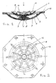
- the diaphragm seen in Figure 1 consists of flexible elastic disk 1, which is constructed in the form of two parts joined to one another, i.e., lower part 2 and upper part 3.
- a central hermetically sealing ridge 5 which is joined to annular hermetically sealing ridges 6, with the aid of which hermetic sealing is ensured between the diaphragm and the valve body.
- ribs 7 On both sides of the hermetically sealing ridge 5 there are provided ribs 7, which are intended for damping the noise and vibrations appearing during operation of the valve.
- the radically arranged, springy ribs 9 create the force and unit pressure needed to ensure hermetic sealing between the diaphragm and the inner surface of the valve body.
- annular hermetically sealing ridges 10 which serve to ensure hermetic sealing between the diaphragm and the valve bonnet.
- the convex part of the upper part 3 is joined to the solid disk 8, which is located on the lower part of the flexible elastic disk.
- a ring 11 which is made as a single unit together with the concave surface of the upper part, from which springy ribs 12 branch out in the radial direction. The latter create only the force needed to return the diaphragm from the uppermost position to the lower position.
- Bearing areas 14 which come into contact with ribs located in the valve body, are provided on the convex surface of the lower part on both sides of the hermetically sealing band perpendicularly to its axis.
- a positive effect greater than the sum of the component parts is achieved in such a design embodiment, since it creates the possibility for maintaining the minimal pressure needed to raise the diaphragm to the uppermost position and for maximally increasing the area of the aperture cross section without increasing its weight, while the lifetime of the diaphragm increases.
- the diaphragm can be constructed as separable components ( Figure 3).
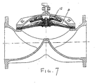
- the diaphragm operates in the following manner (in the example case of a shut-off valve which performs an opening-closing function).
- the two-storeys diaphragm 1 ( Figure 5) is placed on flange 18 of the valve body and covered by bonnet 19 from above.
- the diaphragm is tightly compressed between the bonnet and the valve body with the aid of bolt 20 to ensure hermetic sealing of the joint.
- Three-way valve 21 with the aid of which the operation of the diaphragm is obtained, is placed on the bonnet.
- hermetically sealing ridge 5 is tightly pressed against bearing surface 23 in the valve body by the force created by the pressure P 3 and the force T 9 created by the springy ribs 9.
- bearing areas 14 were provided on the diaphragm (Figure 4). When the diaphragm descends, they lie on rib bearing surface 24 in the valve body ( Figure 5).
- bearing areas 14 increase the cross section of the diaphragm and imparts greater strength to it in these places.
- the force T 12 created by the springy ribs 12 will continue to act as long as they are in contact with the inner surface of the bonnet.
- Such embodiment makes it possible to maintain the minimal pressure needed to open the valve and, at the same time, to create the force needed to return the diaphragm to the lowermost position.
- a valve design with a minimal pressure for opening the valve and a maximal aperture cross-sectional area without an increase in weight can be developed by varying the geometric dimensions of the surface of the upper part and the springy ribs located on it while leaving the geometric dimensions of the lower part of the diaphragm unchanged.
- the lifetime of the diaphragm increases, since, first, the forces created by the springy ribs of the supper and lower parts of the diaphragm are demarcated and, second, there is a possibility for replacing only one part of the diaphragm (upper or lower) in the case of a separable sectional design.
Landscapes
- Engineering & Computer Science (AREA)
- General Engineering & Computer Science (AREA)
- Mechanical Engineering (AREA)
- Safety Valves (AREA)
- Control Of Fluid Pressure (AREA)
- Fluid-Driven Valves (AREA)
Claims (8)
- Eine Federmembran für Absperrventile und Regler, die einen ersten untern Teil (2) in Form einer flexiblen elastischen Scheibe umfasst, der die Funktion einer hermetischen Dichtung erfüllt, die die Einlass- und Auslasskammern des Ventils trennt, und einen zweiten oberen Teil (3) einer kleineren Größe umfasst, der die Funktion einer Feder erfüllt, wobei der zweite obere Teil (3) mit dem ersten Teil integral ist oder mit dem ersten Teil verbunden ist.
- Eine Federmembran für Absperrventile und Regler gemäß Anspruch 1, die in Form einer flexiblen elastischen Scheibe aufgebaut ist, die sanft in eine kugelförmige Oberfläche übergeht; innerhalb der flexiblen elastischen Scheibe ist eine starre kaum zu verformbare dünne elastische Folie (4), zum Beispiel aus Baumwolle, Nylon oder aus einem anderen starren kaum verformbaren Material.
- Eine Federmembran für Absperrventile und Regler gemäß Anspruch 1, worin auf der Oberfläche der flexiblen elastischen Scheibe hermetisch abdichtende Wulste (5, 6) befindlich sind, die als eine einzige Einheit zusammen mit einer langen krummlinigen Oberfläche hergestellt sind.
- Eine Federmembran für Absperrventile und Regler gemäß Anspruch 1, gekennzeichnet durch federnde Rippen (9), die die Kraft und den Einheitsdruck erzeugen, die erforderlich sind, um eine hermetische Dichtung zwischen der Membran und dem Ventilkörper zu sichern, die auf der konkaven Oberfläche des unteren Teils (2) der flexiblen elastischen Scheibe bereitgestellt sind, und durch Rippen (12), die nur die Kraft erzeugen, die erforderlich ist, um die Membran von der oberen Stellung (der Zustand eines geöffneten Ventils) zur unteren Stellung (der Zustand eines geschlossenen Ventils) zurückzuführen, die auf dem oberen Teil (3) der flexiblen elastischen Scheibe angeordnet sind.
- Eine Federmembran für Absperrventile und Regler gemäß Anspruch 1, dadurch gekennzeichnet, dass der obere Teil (3) der flexiblen elastischen Scheibe derart aufgebaut ist, dass die Kraft, die erforderlich ist, um die Membran in die untere Stellung zurückzuführen, nur in dem Augenblick erscheint, wenn der obere Teil mit der inneren Oberfläche der Ventilkappe zusammenwirkt (in Kontakt kommt).
- Eine Federmembran für Absperrventile und Regler gemäß den Ansprüchen 1 bis 5, dadurch gekennzeichnet dass, die oberen und unteren Teile entweder als eine einzige Einheit oder als getrennte Teile aufgebaut werden können, die miteinander durch Befestigungselemente (15, 16, 17) verbunden sind.
- Eine Federmembran für Absperrventile und Regler gemäß den Ansprüchen 1 bis 5, gekennzeichnet durch fehlende Rippen (9, 12) an den unteren und oberen Teilen der flexiblen elastischen Scheibe, um eine gleichmäßig verteilte Kraft über die gesamte aktive Oberfläche der Membran zu erzeugen.
- Eine Federmembran für Absperrventile und Regler gemäß den Ansprüchen 1 bis 5, gekennzeichnet durch Trageabschnitte (14), die auf der konvexen Oberfläche der unteren Schicht (2) geformt sind, die mit tragenden Rippen im Ventilkörper zu dem Zeitpunkt zusammenwirken, zu dem das Ventil geschlossen ist und Druck in der Kammer über der Membran vorhanden ist.
Applications Claiming Priority (2)
| Application Number | Priority Date | Filing Date | Title |
|---|---|---|---|
| IL11996397A IL119963A (en) | 1997-01-05 | 1997-01-05 | Spring diaphragm for shut-off valves and regulators |
| IL11996397 | 1997-01-05 |
Publications (3)
| Publication Number | Publication Date |
|---|---|
| EP0853205A2 EP0853205A2 (de) | 1998-07-15 |
| EP0853205A3 EP0853205A3 (de) | 1998-12-09 |
| EP0853205B1 true EP0853205B1 (de) | 2003-04-09 |
Family
ID=11069661
Family Applications (1)
| Application Number | Title | Priority Date | Filing Date |
|---|---|---|---|
| EP19970122430 Expired - Lifetime EP0853205B1 (de) | 1997-01-05 | 1997-12-18 | Federmembran für Absperrventile und Regler |
Country Status (5)
| Country | Link |
|---|---|
| US (1) | US6095484A (de) |
| EP (1) | EP0853205B1 (de) |
| AU (1) | AU740396C (de) |
| ES (1) | ES2197967T3 (de) |
| IL (1) | IL119963A (de) |
Cited By (1)
| Publication number | Priority date | Publication date | Assignee | Title |
|---|---|---|---|---|
| US7533866B2 (en) | 1998-10-09 | 2009-05-19 | Swagelok Company | Fluid flow body |
Families Citing this family (39)
| Publication number | Priority date | Publication date | Assignee | Title |
|---|---|---|---|---|
| WO1999053388A1 (en) * | 1998-04-09 | 1999-10-21 | Glenborden Pty. Ltd. | Fluid regulator and improvements related thereto |
| US6883780B2 (en) | 1998-10-09 | 2005-04-26 | Swagelok Company | Sanitary diaphragm valve |
| US6505814B1 (en) * | 1998-10-15 | 2003-01-14 | Kabushiki Kaisha Fujikin | Fluid controller |
| ES2178915B1 (es) * | 2000-03-07 | 2004-04-16 | Plasticos Mondragon, S.A. | Valvula hidraulica de membrana perfeccionada, para regulacion del caudal de fluidos. |
| US6354319B1 (en) * | 2000-04-13 | 2002-03-12 | Dresser, Inc. | Low differential, pilot operated fluid pressure regulation apparatus and method |
| USD460526S1 (en) | 2001-03-21 | 2002-07-16 | Bermad Limited Partnership | Control valve |
| USD479577S1 (en) | 2002-01-28 | 2003-09-09 | Tour & Andersson Ab | Pressure regulator |
| US6971634B2 (en) * | 2002-07-08 | 2005-12-06 | Zurn Industries, Inc. | Flush valve diaphragm orifice insert and rib design |
| ITSV20020032A1 (it) * | 2002-07-09 | 2004-01-09 | Alberto Lodolo | Valvola a membrana ed otturatore per detta valvola |
| IL156797A (en) * | 2003-07-06 | 2007-06-17 | Raphael Valves Ind 1975 Ltd | Diaphragm and hydraulically-operated valve using same |
| DE202005002152U1 (de) * | 2005-02-10 | 2006-06-22 | GEMÜ Gebr. Müller Apparatebau GmbH & Co. KG | Membranventil |
| USRE44404E1 (en) | 2005-10-21 | 2013-08-06 | Tyco Fire Products Lp | Ceiling-only dry sprinkler systems and methods for addressing a storage occupancy fire |
| US20100001223A1 (en) * | 2006-03-15 | 2010-01-07 | Norgren, Gmbh | Valve with a springy diaphragm |
| EP3217051B1 (de) | 2006-10-20 | 2020-03-04 | Tyco Fire Products LP | Brandschutzsystem |
| JP5194443B2 (ja) | 2006-12-08 | 2013-05-08 | トヨタ自動車株式会社 | 燃料電池用弁 |
| EP2198163B1 (de) * | 2007-10-02 | 2013-01-02 | Emerson Climate Technologies, Inc. | Verdichter mit verbessertem ventilteller |
| NL1035860C (nl) * | 2008-08-25 | 2010-03-10 | Univ Eindhoven Tech | Inrichting voor het daarin belasten van een medisch product. |
| US8245727B2 (en) | 2009-06-26 | 2012-08-21 | Pamela Mooney, legal representative | Flow control valve and method of use |
| NZ599702A (en) * | 2009-11-09 | 2014-11-28 | Goyen Controls Co | Diaphragm and diaphragm valve |
| US8740177B2 (en) | 2011-07-05 | 2014-06-03 | Rain Bird Corporation | Eccentric diaphragm valve |
| JP5435439B2 (ja) * | 2012-06-22 | 2014-03-05 | Smc株式会社 | 二方弁 |
| US9243718B2 (en) * | 2012-08-27 | 2016-01-26 | Itt Manufacturing Enterprises Llc. | Diaphragm valve having spherically-shaped valve body and diaphragm sealing surface |
| WO2014151971A1 (en) | 2013-03-14 | 2014-09-25 | Tyco Fire Products Lp | Fluid control valve system and methods |
| US9587750B2 (en) | 2013-03-15 | 2017-03-07 | Tyco Fire Products Lp | Fluid control valve system and methods |
| KR20160105801A (ko) * | 2014-01-07 | 2016-09-07 | 썬듀 테크놀로지스 엘엘씨 | 유체-작동식 유량 제어 밸브 |
| US9574673B2 (en) * | 2014-02-06 | 2017-02-21 | Yoram Ringer | Valve for fire protection |
| CN104565429A (zh) * | 2015-01-05 | 2015-04-29 | 宁波耀峰液压电器有限公司 | 一种电控减压输水阀 |
| CN104565430A (zh) * | 2015-01-07 | 2015-04-29 | 宁波耀峰液压电器有限公司 | 一种减压输水阀 |
| CN104806800A (zh) * | 2015-02-13 | 2015-07-29 | 宁波耀峰液压电器有限公司 | 一种减压输水阀 |
| US10436187B2 (en) | 2015-10-29 | 2019-10-08 | Emerson Climate Technologies, Inc. | Cylinder head assembly for reciprocating compressor |
| EP3468674A2 (de) | 2016-06-10 | 2019-04-17 | Tyco Fire Products LP | Brandschutzsysteme und verfahren zur lagerung |
| US11137078B2 (en) | 2016-12-13 | 2021-10-05 | Tyco Fire Products Lp | Fluid control valve having diaphragm that exclusively biases to closed position and methods of fluid control |
| US20190323625A1 (en) | 2018-04-23 | 2019-10-24 | Rain Bird Corporation | Valve With Reinforcement Ports And Manually Removable Scrubber |
| WO2020223513A1 (en) * | 2019-05-02 | 2020-11-05 | Engineered Controls International, Llc | Low-pressure shut-off valve and system |
| AU2021268798A1 (en) * | 2020-05-04 | 2022-12-08 | Aquestia Ltd. | Hydraulically operated valve and systems for use therewith |
| USD975365S1 (en) * | 2020-10-09 | 2023-01-10 | Viking Group, Inc. | Cover of a fluid control valve assembly for fire protection systems |
| DE102021119355A1 (de) | 2021-07-27 | 2023-02-02 | Sisto Armaturen S.A. | Membrananordnung mit querschnittsverengenden Elementen |
| EP4430329A4 (de) | 2021-11-10 | 2025-01-15 | Aquestia Ltd. | Membranventil mit alarmport |
| DE102024117393A1 (de) * | 2024-06-20 | 2025-12-24 | Gemü Gebr. Müller Apparatebau Gmbh & Co. Kommanditgesellschaft | Membranventil, Ventilmembran und Membranlage mit Trennabschnitt |
Family Cites Families (12)
| Publication number | Priority date | Publication date | Assignee | Title |
|---|---|---|---|---|
| US284033A (en) * | 1883-08-28 | Pole and shaft for vehicles | ||
| US2302930A (en) * | 1941-10-06 | 1942-11-24 | Hills Mccanna Co | Valve diaphragm |
| US2710629A (en) * | 1950-02-03 | 1955-06-14 | Saunders Vaive Company Ltd | Flexible diaphragms |
| GB693845A (en) * | 1950-10-09 | 1953-07-08 | Saunders Valve Co Ltd | Improvements in and relating to diaphragm valves |
| US2684829A (en) * | 1951-03-07 | 1954-07-27 | Hills Mccanna Co | Valve diaphragm |
| US2840339A (en) * | 1953-05-13 | 1958-06-24 | Saunders Valve Co Ltd | Diaphragm valves and diaphragms therefor |
| US3011758A (en) * | 1958-05-01 | 1961-12-05 | Hills Mccanna Co | Valve diaphragms |
| US3067764A (en) * | 1960-04-27 | 1962-12-11 | Ladish Co | Diaphragm valves |
| US3130954A (en) * | 1960-04-28 | 1964-04-28 | Hills Mccanna Co | Valve diaphragm structure |
| US3091427A (en) * | 1961-10-10 | 1963-05-28 | Grinnell Corp | Diaphragm valves |
| US3310282A (en) * | 1965-11-15 | 1967-03-21 | Grinnell Corp | Diaphragm control valves |
| DE2839804A1 (de) * | 1978-09-13 | 1980-03-20 | Mersch Fonderies Atel | Membranventil |
-
1997
- 1997-01-05 IL IL11996397A patent/IL119963A/xx not_active IP Right Cessation
- 1997-12-03 US US08/984,345 patent/US6095484A/en not_active Expired - Lifetime
- 1997-12-18 ES ES97122430T patent/ES2197967T3/es not_active Expired - Lifetime
- 1997-12-18 EP EP19970122430 patent/EP0853205B1/de not_active Expired - Lifetime
-
1998
- 1998-01-05 AU AU50371/98A patent/AU740396C/en not_active Ceased
Cited By (1)
| Publication number | Priority date | Publication date | Assignee | Title |
|---|---|---|---|---|
| US7533866B2 (en) | 1998-10-09 | 2009-05-19 | Swagelok Company | Fluid flow body |
Also Published As
| Publication number | Publication date |
|---|---|
| IL119963A (en) | 2003-02-12 |
| ES2197967T3 (es) | 2004-01-16 |
| EP0853205A3 (de) | 1998-12-09 |
| IL119963A0 (en) | 1997-04-15 |
| US6095484A (en) | 2000-08-01 |
| EP0853205A2 (de) | 1998-07-15 |
| AU740396B2 (en) | 2001-11-01 |
| AU5037198A (en) | 1998-07-09 |
| AU740396C (en) | 2007-05-17 |
Similar Documents
| Publication | Publication Date | Title |
|---|---|---|
| US6095484A (en) | Spring diaphragm for shut-off valves and regulators | |
| JP3420241B2 (ja) | 特にマイクロフローチャネルを有する流体操作体用弁 | |
| EP0512674B1 (de) | Durchflussregler | |
| US5909747A (en) | Radial flow diaphragm valve | |
| EP1020779B1 (de) | Ventil mit einem elastomeren Element | |
| CA2124781C (en) | Diaphragm valve | |
| US7059578B2 (en) | Diaphragm and hydraulically-operated valve using same | |
| US5413140A (en) | Spring-assisted split seat gate valve | |
| US7240740B2 (en) | Diaphragm valve with pivoting closure member | |
| JPH08270832A (ja) | 閉止弁向けのステム先端のシール構造体 | |
| KR20000048199A (ko) | 유량제어밸브 | |
| US7331359B2 (en) | Valve with bi-loading seal | |
| US3394914A (en) | Fluid pressure responsive sealing butterfly valve | |
| US4659062A (en) | Flowgrid regulator | |
| AU641229B2 (en) | A diaphragm valve | |
| US5104090A (en) | Irrigation valve | |
| EP1592906B1 (de) | Buchsenloses schaftgesteuertes regelventil | |
| EP0134866A2 (de) | Schaltventil | |
| JPS6229669B2 (de) | ||
| EP0928917B1 (de) | Ventilmembran | |
| US20030155541A1 (en) | Pressure enhanced diaphragm valve | |
| EP0124567B1 (de) | Ventile | |
| KR102221841B1 (ko) | 기밀성이 향상된 밸브 조립체 | |
| EP0513268A1 (de) | Membranventil | |
| JP2001017563A (ja) | 一斉開放弁 |
Legal Events
| Date | Code | Title | Description |
|---|---|---|---|
| PUAI | Public reference made under article 153(3) epc to a published international application that has entered the european phase |
Free format text: ORIGINAL CODE: 0009012 |
|
| AK | Designated contracting states |
Kind code of ref document: A2 Designated state(s): ES FR GR IT |
|
| AX | Request for extension of the european patent |
Free format text: AL;LT;LV;MK;RO;SI |
|
| RIN1 | Information on inventor provided before grant (corrected) |
Inventor name: FRANKEL, BORIS, DR. |
|
| PUAL | Search report despatched |
Free format text: ORIGINAL CODE: 0009013 |
|
| AK | Designated contracting states |
Kind code of ref document: A3 Designated state(s): AT BE CH DE DK ES FI FR GB GR IE IT LI LU MC NL PT SE |
|
| AX | Request for extension of the european patent |
Free format text: AL;LT;LV;MK;RO;SI |
|
| 17P | Request for examination filed |
Effective date: 19990517 |
|
| AKX | Designation fees paid |
Free format text: DE ES FR GR IT |
|
| RBV | Designated contracting states (corrected) |
Designated state(s): ES FR GR IT |
|
| REG | Reference to a national code |
Ref country code: DE Ref legal event code: 8566 |
|
| GRAH | Despatch of communication of intention to grant a patent |
Free format text: ORIGINAL CODE: EPIDOS IGRA |
|
| GRAH | Despatch of communication of intention to grant a patent |
Free format text: ORIGINAL CODE: EPIDOS IGRA |
|
| RIN1 | Information on inventor provided before grant (corrected) |
Inventor name: FRENKEL, BORIS, DR. |
|
| GRAA | (expected) grant |
Free format text: ORIGINAL CODE: 0009210 |
|
| AK | Designated contracting states |
Designated state(s): ES FR GR IT |
|
| REG | Reference to a national code |
Ref country code: GR Ref legal event code: EP Ref document number: 20030402571 Country of ref document: GR |
|
| PGFP | Annual fee paid to national office [announced via postgrant information from national office to epo] |
Ref country code: GR Payment date: 20031202 Year of fee payment: 7 |
|
| PGFP | Annual fee paid to national office [announced via postgrant information from national office to epo] |
Ref country code: ES Payment date: 20031217 Year of fee payment: 7 |
|
| PGFP | Annual fee paid to national office [announced via postgrant information from national office to epo] |
Ref country code: FR Payment date: 20031229 Year of fee payment: 7 |
|
| RAP2 | Party data changed (patent owner data changed or rights of a patent transferred) |
Owner name: RAPHAEL VALVES INDUSTRIES (1975) LTD. |
|
| REG | Reference to a national code |
Ref country code: ES Ref legal event code: FG2A Ref document number: 2197967 Country of ref document: ES Kind code of ref document: T3 |
|
| ET | Fr: translation filed | ||
| PLBE | No opposition filed within time limit |
Free format text: ORIGINAL CODE: 0009261 |
|
| STAA | Information on the status of an ep patent application or granted ep patent |
Free format text: STATUS: NO OPPOSITION FILED WITHIN TIME LIMIT |
|
| 26N | No opposition filed |
Effective date: 20040112 |
|
| PG25 | Lapsed in a contracting state [announced via postgrant information from national office to epo] |
Ref country code: ES Free format text: LAPSE BECAUSE OF NON-PAYMENT OF DUE FEES Effective date: 20041220 |
|
| PG25 | Lapsed in a contracting state [announced via postgrant information from national office to epo] |
Ref country code: GR Free format text: LAPSE BECAUSE OF NON-PAYMENT OF DUE FEES Effective date: 20050704 |
|
| PG25 | Lapsed in a contracting state [announced via postgrant information from national office to epo] |
Ref country code: FR Free format text: LAPSE BECAUSE OF NON-PAYMENT OF DUE FEES Effective date: 20050831 |
|
| REG | Reference to a national code |
Ref country code: FR Ref legal event code: ST |
|
| PG25 | Lapsed in a contracting state [announced via postgrant information from national office to epo] |
Ref country code: IT Free format text: LAPSE BECAUSE OF NON-PAYMENT OF DUE FEES Effective date: 20051218 |
|
| REG | Reference to a national code |
Ref country code: ES Ref legal event code: FD2A Effective date: 20041220 |