EP0853215A2 - Dispositif de combustion pour matériaux pulvérulents - Google Patents
Dispositif de combustion pour matériaux pulvérulents Download PDFInfo
- Publication number
- EP0853215A2 EP0853215A2 EP98105588A EP98105588A EP0853215A2 EP 0853215 A2 EP0853215 A2 EP 0853215A2 EP 98105588 A EP98105588 A EP 98105588A EP 98105588 A EP98105588 A EP 98105588A EP 0853215 A2 EP0853215 A2 EP 0853215A2
- Authority
- EP
- European Patent Office
- Prior art keywords
- air
- combustion
- combustion chamber
- inlet
- secondary air
- Prior art date
- Legal status (The legal status is an assumption and is not a legal conclusion. Google has not performed a legal analysis and makes no representation as to the accuracy of the status listed.)
- Withdrawn
Links
- 238000002485 combustion reaction Methods 0.000 title claims abstract description 123
- 239000000463 material Substances 0.000 title claims abstract description 27
- 239000003546 flue gas Substances 0.000 claims description 19
- 238000007664 blowing Methods 0.000 claims description 10
- 239000000446 fuel Substances 0.000 claims description 10
- UGFAIRIUMAVXCW-UHFFFAOYSA-N Carbon monoxide Chemical compound [O+]#[C-] UGFAIRIUMAVXCW-UHFFFAOYSA-N 0.000 claims description 8
- 239000002826 coolant Substances 0.000 claims description 7
- 238000004056 waste incineration Methods 0.000 claims description 6
- 238000001816 cooling Methods 0.000 claims description 5
- 238000004140 cleaning Methods 0.000 claims description 4
- 229910052698 phosphorus Inorganic materials 0.000 claims description 4
- 238000000227 grinding Methods 0.000 claims description 3
- 239000011819 refractory material Substances 0.000 claims description 3
- 238000011144 upstream manufacturing Methods 0.000 claims description 3
- 238000012544 monitoring process Methods 0.000 claims description 2
- 238000005192 partition Methods 0.000 claims description 2
- 229910052717 sulfur Inorganic materials 0.000 claims description 2
- 238000002347 injection Methods 0.000 claims 4
- 239000007924 injection Substances 0.000 claims 4
- 230000002265 prevention Effects 0.000 claims 2
- 238000002360 preparation method Methods 0.000 claims 1
- 239000000428 dust Substances 0.000 abstract description 10
- 239000007789 gas Substances 0.000 abstract description 5
- 239000000203 mixture Substances 0.000 description 20
- 239000003344 environmental pollutant Substances 0.000 description 13
- 231100000719 pollutant Toxicity 0.000 description 13
- 239000000571 coke Substances 0.000 description 10
- 150000002013 dioxins Chemical class 0.000 description 9
- 238000010304 firing Methods 0.000 description 8
- 230000006378 damage Effects 0.000 description 6
- 238000002156 mixing Methods 0.000 description 6
- 238000013461 design Methods 0.000 description 5
- OKTJSMMVPCPJKN-UHFFFAOYSA-N Carbon Chemical compound [C] OKTJSMMVPCPJKN-UHFFFAOYSA-N 0.000 description 4
- 150000002240 furans Chemical class 0.000 description 4
- 239000000126 substance Substances 0.000 description 4
- MWUXSHHQAYIFBG-UHFFFAOYSA-N nitrogen oxide Inorganic materials O=[N] MWUXSHHQAYIFBG-UHFFFAOYSA-N 0.000 description 3
- 150000003071 polychlorinated biphenyls Chemical class 0.000 description 3
- IJGRMHOSHXDMSA-UHFFFAOYSA-N Atomic nitrogen Chemical compound N#N IJGRMHOSHXDMSA-UHFFFAOYSA-N 0.000 description 2
- 230000015572 biosynthetic process Effects 0.000 description 2
- 150000001875 compounds Chemical class 0.000 description 2
- 238000010586 diagram Methods 0.000 description 2
- 230000000694 effects Effects 0.000 description 2
- 238000003780 insertion Methods 0.000 description 2
- 230000037431 insertion Effects 0.000 description 2
- 238000012545 processing Methods 0.000 description 2
- 238000000926 separation method Methods 0.000 description 2
- 239000010801 sewage sludge Substances 0.000 description 2
- -1 PCT Chemical class 0.000 description 1
- 238000010521 absorption reaction Methods 0.000 description 1
- QVGXLLKOCUKJST-UHFFFAOYSA-N atomic oxygen Chemical compound [O] QVGXLLKOCUKJST-UHFFFAOYSA-N 0.000 description 1
- 230000033228 biological regulation Effects 0.000 description 1
- UQMRAFJOBWOFNS-UHFFFAOYSA-N butyl 2-(2,4-dichlorophenoxy)acetate Chemical compound CCCCOC(=O)COC1=CC=C(Cl)C=C1Cl UQMRAFJOBWOFNS-UHFFFAOYSA-N 0.000 description 1
- 230000003197 catalytic effect Effects 0.000 description 1
- 238000006243 chemical reaction Methods 0.000 description 1
- 239000003245 coal Substances 0.000 description 1
- 239000000109 continuous material Substances 0.000 description 1
- 230000001419 dependent effect Effects 0.000 description 1
- 238000011161 development Methods 0.000 description 1
- 238000005516 engineering process Methods 0.000 description 1
- 238000009472 formulation Methods 0.000 description 1
- 230000005283 ground state Effects 0.000 description 1
- 239000002920 hazardous waste Substances 0.000 description 1
- 229910001385 heavy metal Inorganic materials 0.000 description 1
- 229930195733 hydrocarbon Natural products 0.000 description 1
- 150000002430 hydrocarbons Chemical class 0.000 description 1
- 239000003077 lignite Substances 0.000 description 1
- 238000012423 maintenance Methods 0.000 description 1
- 229910052757 nitrogen Inorganic materials 0.000 description 1
- 150000002894 organic compounds Chemical class 0.000 description 1
- 229910052760 oxygen Inorganic materials 0.000 description 1
- 239000001301 oxygen Substances 0.000 description 1
- 231100000614 poison Toxicity 0.000 description 1
- 239000002243 precursor Substances 0.000 description 1
- 239000010865 sewage Substances 0.000 description 1
- 239000000779 smoke Substances 0.000 description 1
- 238000001228 spectrum Methods 0.000 description 1
- 230000006641 stabilisation Effects 0.000 description 1
- 238000011105 stabilization Methods 0.000 description 1
- XTQHKBHJIVJGKJ-UHFFFAOYSA-N sulfur monoxide Chemical class S=O XTQHKBHJIVJGKJ-UHFFFAOYSA-N 0.000 description 1
- 229910052815 sulfur oxide Inorganic materials 0.000 description 1
- 150000001911 terphenyls Chemical class 0.000 description 1
- 231100000167 toxic agent Toxicity 0.000 description 1
- 239000003440 toxic substance Substances 0.000 description 1
- 239000003053 toxin Substances 0.000 description 1
- 231100000765 toxin Toxicity 0.000 description 1
- 108700012359 toxins Proteins 0.000 description 1
- 238000012549 training Methods 0.000 description 1
- 238000012546 transfer Methods 0.000 description 1
Images

Classifications
-
- F—MECHANICAL ENGINEERING; LIGHTING; HEATING; WEAPONS; BLASTING
- F23—COMBUSTION APPARATUS; COMBUSTION PROCESSES
- F23C—METHODS OR APPARATUS FOR COMBUSTION USING FLUID FUEL OR SOLID FUEL SUSPENDED IN A CARRIER GAS OR AIR
- F23C7/00—Combustion apparatus characterised by arrangements for air supply
- F23C7/02—Disposition of air supply not passing through burner
-
- F—MECHANICAL ENGINEERING; LIGHTING; HEATING; WEAPONS; BLASTING
- F23—COMBUSTION APPARATUS; COMBUSTION PROCESSES
- F23C—METHODS OR APPARATUS FOR COMBUSTION USING FLUID FUEL OR SOLID FUEL SUSPENDED IN A CARRIER GAS OR AIR
- F23C3/00—Combustion apparatus characterised by the shape of the combustion chamber
- F23C3/006—Combustion apparatus characterised by the shape of the combustion chamber the chamber being arranged for cyclonic combustion
- F23C3/008—Combustion apparatus characterised by the shape of the combustion chamber the chamber being arranged for cyclonic combustion for pulverulent fuel
-
- F—MECHANICAL ENGINEERING; LIGHTING; HEATING; WEAPONS; BLASTING
- F23—COMBUSTION APPARATUS; COMBUSTION PROCESSES
- F23C—METHODS OR APPARATUS FOR COMBUSTION USING FLUID FUEL OR SOLID FUEL SUSPENDED IN A CARRIER GAS OR AIR
- F23C6/00—Combustion apparatus characterised by the combination of two or more combustion chambers or combustion zones, e.g. for staged combustion
- F23C6/04—Combustion apparatus characterised by the combination of two or more combustion chambers or combustion zones, e.g. for staged combustion in series connection
-
- F—MECHANICAL ENGINEERING; LIGHTING; HEATING; WEAPONS; BLASTING
- F23—COMBUSTION APPARATUS; COMBUSTION PROCESSES
- F23G—CREMATION FURNACES; CONSUMING WASTE PRODUCTS BY COMBUSTION
- F23G5/00—Incineration of waste; Incinerator constructions; Details, accessories or control therefor
- F23G5/32—Incineration of waste; Incinerator constructions; Details, accessories or control therefor the waste being subjected to a whirling movement, e.g. cyclonic incinerators
-
- F—MECHANICAL ENGINEERING; LIGHTING; HEATING; WEAPONS; BLASTING
- F23—COMBUSTION APPARATUS; COMBUSTION PROCESSES
- F23M—CASINGS, LININGS, WALLS OR DOORS SPECIALLY ADAPTED FOR COMBUSTION CHAMBERS, e.g. FIREBRIDGES; DEVICES FOR DEFLECTING AIR, FLAMES OR COMBUSTION PRODUCTS IN COMBUSTION CHAMBERS; SAFETY ARRANGEMENTS SPECIALLY ADAPTED FOR COMBUSTION APPARATUS; DETAILS OF COMBUSTION CHAMBERS, NOT OTHERWISE PROVIDED FOR
- F23M5/00—Casings; Linings; Walls
- F23M5/08—Cooling thereof; Tube walls
- F23M5/085—Cooling thereof; Tube walls using air or other gas as the cooling medium
-
- F—MECHANICAL ENGINEERING; LIGHTING; HEATING; WEAPONS; BLASTING
- F23—COMBUSTION APPARATUS; COMBUSTION PROCESSES
- F23D—BURNERS
- F23D2900/00—Special features of, or arrangements for burners using fluid fuels or solid fuels suspended in a carrier gas
- F23D2900/00014—Pilot burners specially adapted for ignition of main burners in furnaces or gas turbines
-
- F—MECHANICAL ENGINEERING; LIGHTING; HEATING; WEAPONS; BLASTING
- F23—COMBUSTION APPARATUS; COMBUSTION PROCESSES
- F23G—CREMATION FURNACES; CONSUMING WASTE PRODUCTS BY COMBUSTION
- F23G2201/00—Pretreatment
- F23G2201/80—Shredding
-
- F—MECHANICAL ENGINEERING; LIGHTING; HEATING; WEAPONS; BLASTING
- F23—COMBUSTION APPARATUS; COMBUSTION PROCESSES
- F23G—CREMATION FURNACES; CONSUMING WASTE PRODUCTS BY COMBUSTION
- F23G2205/00—Waste feed arrangements
- F23G2205/20—Waste feed arrangements using airblast or pneumatic feeding
-
- F—MECHANICAL ENGINEERING; LIGHTING; HEATING; WEAPONS; BLASTING
- F23—COMBUSTION APPARATUS; COMBUSTION PROCESSES
- F23G—CREMATION FURNACES; CONSUMING WASTE PRODUCTS BY COMBUSTION
- F23G2207/00—Control
- F23G2207/40—Supplementary heat supply
-
- F—MECHANICAL ENGINEERING; LIGHTING; HEATING; WEAPONS; BLASTING
- F23—COMBUSTION APPARATUS; COMBUSTION PROCESSES
- F23G—CREMATION FURNACES; CONSUMING WASTE PRODUCTS BY COMBUSTION
- F23G2209/00—Specific waste
- F23G2209/12—Sludge, slurries or mixtures of liquids
-
- F—MECHANICAL ENGINEERING; LIGHTING; HEATING; WEAPONS; BLASTING
- F23—COMBUSTION APPARATUS; COMBUSTION PROCESSES
- F23G—CREMATION FURNACES; CONSUMING WASTE PRODUCTS BY COMBUSTION
- F23G2209/00—Specific waste
- F23G2209/30—Solid combustion residues, e.g. bottom or flyash
-
- F—MECHANICAL ENGINEERING; LIGHTING; HEATING; WEAPONS; BLASTING
- F23—COMBUSTION APPARATUS; COMBUSTION PROCESSES
- F23G—CREMATION FURNACES; CONSUMING WASTE PRODUCTS BY COMBUSTION
- F23G2900/00—Special features of, or arrangements for incinerators
- F23G2900/50001—Combination of two or more furnaces
Definitions
- the present invention relates to a device for Burning dusty materials, especially Activated coke dust from filter systems contaminated with pollutants, Sewage sludge dust and the like, according to the preamble of claim 1.
- a device according to the preamble of the independent Claim 1 is known from DE-B-1 024 191.
- This Document describes a "cyclone firing", where a fuel (fuel dust) air mixture via entry slots with Twist (rotary motion) is inserted into a cyclone muffle.
- Combustion air (primary air) is also also introduced with twist, with the same direction of rotation like the fuel-air mixture.
- outlet slots for secondary air (secondary air) arranged such that the Second air also flows in with swirl, namely in the the fuel dust-air mixture opposite direction of the opposite inlet and either with the same or with the opposite direction of rotation as the fuel-air mixture.
- EP-A-0 409 037 describes a different combustion chamber in that than doing no counterflow of primary and Secondary air, but only rectified, moving towards of an output described swirling flows are.
- this publication is also not concerned with the special problem of thermal destruction of Pollutants.
- This document describes one first substoichiometric combustion with primary and secondary air as well as a subsequent complete combustion by means of excess air achieved by tertiary air, however must the substoichiometric combustion according to the overall disclosure this document obviously with a extremely serious lack of air ( ⁇ «1) because the The temperature remains "below the ash softening point" should, i.e. below 1100 ° C. So it is about a relatively lower temperature than the subsequent one complete combustion.
- the present invention has for its object a Device for burning such contaminated materials to create, with what is structurally simple as well compact structure the special, for safe pollutant destruction required combustion conditions on simple Are controllable.
- the combustion device should preferably for a continuous Material throughput are suitable, so that an economical Operation especially in direct combination with such facilities is possible in which the contaminated Materials.
- the combustion device has a Combustion chamber with a one-sided inlet opening for the burning material and one opposite the inlet opening Exhaust opening for combustion Flue gases on, in the area of the inlet opening a device for introducing itself with the to be burned, dusty material of primary air mixing and in the area of the outlet opening a device for Introducing secondary air are provided such that the Secondary air on the one hand opposite the primary air in the direction the inlet opening flows and on the other hand into a Swirl flow around an inlet and outlet opening Combustion chamber axis is offset.
- there is an afterburning zone at the outlet in which then - in addition to the primary and secondary air - Tertiary air is introduced.
- the combustion can advantageously be carried out by metering Supply of primary, secondary and tertiary air like this control that overall at least approximately a stoichiometric Combustion is achieved.
- ⁇ For security reasons - to always be complete
- ⁇ To be able to ensure combustion - lies ⁇ according to the invention on the order of about 1.02.
- This extremely small excess air is of decisive advantage in that as a fire temperature drop due to too big Excess air is avoided, i.e. the firing temperature can be kept very high and permanent. It is complete combustion with thermal destruction of all pollutants occurring in practice, in particular also of dioxins.
- the term "complete combustion" means that by the invention in the flue gas only an extraordinary low percentage of unburned substances, namely ⁇ 0.1% is included. The one usually required here The limit value of a maximum of 5% unburned is therefore advantageously far below. Furthermore, the preferred near-stoichiometric combustion also a new formation of dioxins and the like advantageously avoided because of such reactions because of the low Air excess of around 2% in particular is not enough Oxygen is available.
- tertiary air supplied in the afterburning zone can be substoichiometric within the combustion chamber are burned, then total, i.e. through primary, Secondary and tertiary air, preferably approximately stoichiometric Combustion with ⁇ ⁇ 1.02 is achieved.
- the substoichiometric Burning in the combustion chamber leads to a higher combustion temperature and thereby a even safer removal of pollutants, in particular Dioxins.
- the afterburning caused by supplying tertiary air practically leads to a completion of the Incineration in such a way that overall the intended full Combustion is achieved.
- burned can be, for example, when a lower temperature from e.g. about 1200 ° C should be reached.
- a lower temperature from e.g. about 1200 ° C should be reached.
- a very stable combustion due to the homogeneity of the mixture.
- the primary air too is set in a swirl flow, the swirl directions of primary air and secondary air opposed to each other are directed.
- too Tertiary air swirled; are here then the swirl directions of secondary air and tertiary air facing each other.
- the invention Device thus around a "multi-stage counter-swirl burner".
- ⁇ 1
- a Control range of 1:20 can be achieved without that Influencing stability of the flame.
- optimal, complete combustion over a control range guaranteed from full load to 1/20 of full load can be.
- the device is for 1000 kg Designed for full load, even at 1/20, i.e. 50 kg, a complete, optimal combustion can be achieved, even at a temperature of around 1800 ° C.
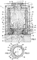
- FIG. 1 there is an inventive Device 1 for burning dust Materials mainly from a combustion chamber 2 with a one-sided inlet opening 4 for the material to be burned and also for supplied combustion air as well as with a the inlet opening 4 opposite in the throughput direction Outlet opening 6 for flue gases resulting from the combustion.
- the inlet and outlet openings 4, 6 are preferably coaxial arranged to each other, i.e. a combustion chamber axis 8 runs in particular centrally through the inputs and Outlet openings 4, 6.
- the material to be burned is in dust form, i.e. in ground state, supplied via a pipeline 10, this pipeline 10 in the area of the inlet opening 4 flows.
- This material is a certain percentage of air attached so that a dust-air mixture is already from the pipe 10 exit. However, this mixture becomes additional Combustion air supplied.
- the combustion air is initially in primary air P and secondary air S divided, in the area of the inlet opening 4th a device 12 for introducing the to be burned Material mixing primary air P and in Area of the outlet opening 6 a device 14 for insertion the secondary air S are provided such that the Secondary air S, on the one hand, of the primary air P or the air from it resulting dust-air mixture in the opposite direction Inlet opening 4 flows and on the other hand in a Swirl flow around the combustion chamber axis 8 is offset.
- swirl flow of the secondary air S will increase the residence time of the flammable mixture reached within the combustion chamber 2 and also a such intensive swirling and mixing that a almost homogeneous fuel mixture is generated. Result from this optimal combustion conditions.
- the device is 12 to introduce the primary air P only in the form of a short, preferably cylindrical, the inlet opening at the same time 4 tube piece 16 formed such that the primary air P with the entrainment of the combustion Material initially essentially straight, i.e. as approximately homogeneous flow, through the inlet opening 4 in the direction the outlet opening 6 is blown.
- the fuel mixture is then the opposite Swirl flow of the secondary air S intensive swirled.
- the primary air P is formed such that the primary air P taking the material to be burned on the one hand the secondary air S in the direction of the outlet opening 6 flows and on the other hand also in a swirl flow is displaced about the combustion chamber axis 8.
- the swirl direction of the primary air P or of the dust-air mixture the swirl direction of the secondary air S opposite.
- This swirl flap device 18 is to generate the Swirl flow of the primary air P, i.e. as a device 12 for Introducing the primary air P within the inlet opening 4 a swirl flap device 18 with in particular for changing the swirl inclination-adjustable swirl flaps 20 are arranged.
- This swirl flap device 18 is in the manner of a Turbine wheel or an axial fan, wherein the swirl flaps over the circumference of the inlet opening 4 evenly spaced around radial axes are in particular continuously pivotable, namely between an axially aligned arrangement and one approximately vertical arrangement, the opening 4 then almost closed is. This can also have a certain Regulation of the air volume can be achieved.
- serves the swirl flap device 18 for variability in the swirl effect or swirl intensity of the primary air-dust mixture.
- the device 14 for introducing the secondary air S essentially from a surrounding the outlet opening 6 or to the outlet opening 6 concentric blowing ring 22, one in the direction of the combustion chamber 2 conically widening inner surface 24 and several over the Has circumferentially distributed louvers 26.
- This Air slots 26 extend from the outer periphery 28 of the blowing ring 22 to the inner surface 24 and are such aligned that the secondary air supplied from the outside S flows through the louvers 26 and thereby into the in the combustion chamber 2 directed swirl flow is offset.
- the blowing ring is 22 expediently of several individual ring elements 30 formed, each between the louvers 26 form or limit.
- ring elements 30 by means of suitable holding means, not described in detail fixed in position or clamped.
- the blowing ring 22 consists of about twenty-four individual ones Elements, so that a total of twenty-four louvers in an even distribution over the circumference are provided.
- the number of ring elements 30 or Air slots 26 can vary widely, however, in Depending on the design of the burner output and the amount of air required in each case.
- Louvers 26 of the blowing ring 22 in terms of their effective flow cross-section formed in such a nozzle-like manner are that the outside with a certain, i.e. by that required for complete combustion at ⁇ ⁇ 1 Air volume specified, inlet pressure supplied secondary air S through the narrowed louvers 26 one such high flow rate maintains that it penetrates of fuels in the louvers 26 prevented.
- self-cleaning is advantageously practical or self-maintenance of the louvers 26 achieved by the injected secondary air S.
- tertiary air T is supplied.
- Conveniently for this purpose connects to the outlet opening 6 in the direction facing away from the combustion chamber 2 is a post-combustion zone 32 with a device 34 for feeding the Tertiary air T on.
- the combustion inside the combustion chamber 2 sub-stoichiometric with an excess air number or "lack of air" ⁇ ⁇ 1. It can thereby a particularly high temperature to absolute safe destruction of pollutants, especially dioxins, can be achieved.
- the tertiary air T with a volume per unit time is supplied that preferably the overall combustion is approximately stoichiometric ( ⁇ about 1.02).
- the overall combustion is approximately stoichiometric ( ⁇ about 1.02).
- ⁇ about 1.02
- excess air e.g. ⁇ ⁇ 1.9
- the device 34 for supplying the tertiary air T is such trained that the tertiary air T on the one hand in the the combustion chamber 2 opposite direction of the post-combustion zone 32 flows, but on the other hand also in a swirl flow is displaced, whereby the dwell time within the post-combustion zone 32 is increased.
- the swirl directions of tertiary air and secondary air opposed to each other This will make a repeat Mixing and swirling of the fuel mixture reached.
- the device 34 also expediently exists for supplying the tertiary air T from a to the outlet opening 6 concentric blowing ring 36, which in its constructive Design basically that for the secondary air S provided blowing ring 22 corresponds, so that on this For the sake of simplicity, refer to the above statements is referred. To this end, the same or functional corresponding parts with the same reference numerals. Of particular note, however, is that the conical inner surface 24 of the blowing ring 36 into the Combustion chamber 2 extends in the opposite direction. Also are the air slots 26 are also formed in the blowing ring 36, that the tertiary air T has such a high flow rate maintains that it penetrates substances effectively prevented from the flue gases. As tertiary air T cold fresh air is expediently used (with Outside or ambient temperature).
- the primary air P and preferably also the secondary air S before it is introduced into the combustion chamber 2 expediently heated.
- the combustion chamber 2 is delimited by a chamber wall 38 , which in turn is enclosed by an outer jacket 40 in this way is that between the chamber wall 38 and the Sheath 40 a cavity enclosing the chamber wall 38 42 is formed.
- this cavity 42 opens into one of the Outlet opening 6 near area an air inlet 44, and the cavity 42 goes on that facing away from the outlet opening 6 Side in the inlet opening 4 over.
- a helical extending partition 46 arranged such that the Air supplied via the air inlet 44 to the chamber wall 38 flows around helically in the direction of the inlet opening 4. This ensures good and effective heat absorption or heat transfer from the combustion chamber 2 via the Chamber wall 38 reached on the air (heat exchanger). This also contributes to the fact that within the combustion chamber 2 very high firing temperatures can be achieved.
- the chamber wall 38 is advantageously cooled.
- the invention is also Device 1 the combustion chamber 2 with an inner jacket 48 lined with a refractory material.
- the for this are commonly used refractory materials however only up to an average temperature of about Resistant at 1600 ° C. Therefore, it is due to the very high Combustion chamber temperatures of up to 2000 ° C are particularly advantageous, if between the chamber wall 38 and the refractory Inner jacket 48 a cavity enclosing the latter 50 formed for a cooling medium cooling the inner jacket 48 is.
- the secondary air S is used as the cooling medium, for which purpose preferably the via the air inlet 44 and between the Chamber wall 38 and the outer shell 40 formed cavity 42 supplied air in front of the inlet opening 4 Area divided into the primary air P and the secondary air S.
- Burner 54 is used on the one hand for the first ignition in start-up mode the combustion device 1 according to the invention. Once a regular combustion inside the combustion chamber 2 is reached, this burner 54 can be switched off will.
- the pilot and auxiliary burner 54 preferably controlled automatically by a controller, that in the event of an irregularity within the Combustion chamber 2 running combustion of the pilot and auxiliary burners 54 automatically switched on for a certain time becomes.
- the burner 54 switching control for monitoring the one hand in the Combustion chamber 2 running combustion and on the other hand the Flame of the burner 54, in particular photocells or the same sensors.
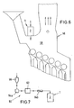
- the combustion chamber 2 is thus directly on a combustion boiler 56 in particular a waste incineration plant arranged that exiting through the outlet opening 6 Flue gases directly into the combustion chamber 58 of the combustion boiler 56 can be initiated.
- This is preferably Arrangement of the device 1 according to the invention on the combustion boiler 56 chosen such that the flue gases in one Enter the area of the combustion chamber 58 in which one Operating temperature ⁇ 1200 ° C. This is advantageous undercooling the combustion chamber flame Edge influences and streak formation in the firebox are excluded.
- the application according to the invention is suitable for this application Device 1 in particular for burning the in the Waste incineration system of activated coke, advantageously a steady throughput, i.e. a steady Disposal is possible. It also provides thermal support the one running inside the combustion boiler 56 Combustion reached. That from the invention Device 1 originating flue gas is then together with the Flue gases from a conventional incinerator Flue gas cleaning supplied.
- the combustion chamber 2 is a processing device 60 upstream for the material to be burned, which in particular from a grinding device 62 and transport devices 64 exists.
- the one that arises Activated coke from an intermediate silo 66 via a pneumatic one Conveyor system 64a in particular with nitrogen to the Grinding device 62 promoted and there for a secured Burning down the necessary fineness.
- Of the Ground coke dust is then passed through a rotary valve 64b carried out and further by means of the combustion air dosed fed.
- Each unit is separate advantageously designed to have a maximum Active coke can be disposed of continuously. This means, that each combustion boiler with its own combustion device is equipped so that by this Amount of activated coke directly in the boiler can be disposed of again.
- the invention is not based on the illustrated and described Embodiments limited, but also includes all designs having the same effect in the sense of the invention. Furthermore, the invention is not yet based on the Claim 1 defined combination of features limited, but can also be by any other combination of certain characteristics of all of the individual characteristics disclosed be defined. This means that basically practically every single feature of claim 1 omitted or by at least one elsewhere in the registration disclosed individual feature can be replaced. To that extent is claim 1 only as a first attempt at formulation to understand for an invention.
Landscapes
- Engineering & Computer Science (AREA)
- Mechanical Engineering (AREA)
- General Engineering & Computer Science (AREA)
- Chemical & Material Sciences (AREA)
- Combustion & Propulsion (AREA)
- Incineration Of Waste (AREA)
- Solid-Fuel Combustion (AREA)
- Combustion Of Fluid Fuel (AREA)
- Glass Compositions (AREA)
Applications Claiming Priority (3)
| Application Number | Priority Date | Filing Date | Title |
|---|---|---|---|
| DE4409951 | 1994-03-23 | ||
| DE4409951A DE4409951A1 (de) | 1994-03-23 | 1994-03-23 | Vorrichtung zum Verbrennen von staubförmigen Materialien |
| EP95103739A EP0674134B1 (fr) | 1994-03-23 | 1995-03-15 | Procédé de combustion pour matériaux pulvérulents |
Related Parent Applications (1)
| Application Number | Title | Priority Date | Filing Date |
|---|---|---|---|
| EP95103739A Division EP0674134B1 (fr) | 1994-03-23 | 1995-03-15 | Procédé de combustion pour matériaux pulvérulents |
Publications (2)
| Publication Number | Publication Date |
|---|---|
| EP0853215A2 true EP0853215A2 (fr) | 1998-07-15 |
| EP0853215A3 EP0853215A3 (fr) | 1998-12-30 |
Family
ID=6513572
Family Applications (2)
| Application Number | Title | Priority Date | Filing Date |
|---|---|---|---|
| EP98105588A Withdrawn EP0853215A3 (fr) | 1994-03-23 | 1995-03-15 | Dispositif de combustion pour matériaux pulvérulents |
| EP95103739A Expired - Lifetime EP0674134B1 (fr) | 1994-03-23 | 1995-03-15 | Procédé de combustion pour matériaux pulvérulents |
Family Applications After (1)
| Application Number | Title | Priority Date | Filing Date |
|---|---|---|---|
| EP95103739A Expired - Lifetime EP0674134B1 (fr) | 1994-03-23 | 1995-03-15 | Procédé de combustion pour matériaux pulvérulents |
Country Status (4)
| Country | Link |
|---|---|
| EP (2) | EP0853215A3 (fr) |
| AT (1) | ATE180558T1 (fr) |
| DE (2) | DE4409951A1 (fr) |
| ES (2) | ES2081788T1 (fr) |
Cited By (3)
| Publication number | Priority date | Publication date | Assignee | Title |
|---|---|---|---|---|
| WO2000075564A1 (fr) * | 1999-06-08 | 2000-12-14 | Nunez Suarez, Mario | Procede et dispositif de transfert de chaleur et de combustion sous pression |
| WO2002086405A3 (fr) * | 2001-04-20 | 2002-12-19 | Ebara Corp | Four de combustion a scorification |
| CN107702745A (zh) * | 2017-09-13 | 2018-02-16 | 绿色动力环保集团股份有限公司 | 一种垃圾焚烧炉烟气停留时间的在线动态计算方法及系统 |
Families Citing this family (8)
| Publication number | Priority date | Publication date | Assignee | Title |
|---|---|---|---|---|
| DE19806823C2 (de) * | 1998-02-18 | 1999-12-09 | Loesche Gmbh | Vorrichtung und Verfahren zur Verbrennung vanadiumhaltiger Brennstoffe |
| AT406901B (de) * | 1998-04-17 | 2000-10-25 | Andritz Patentverwaltung | Verfahren und vorrichtung zur verbrennung von partikelförmigen feststoffen |
| DE10140422C1 (de) * | 2001-08-17 | 2002-11-28 | Eisenmann Kg Maschbau | Thermische Nachverbrennungsvorrichtung |
| DE102007055113B4 (de) | 2007-11-19 | 2017-05-24 | Volkswagen Ag | Scheibenwischeranlage an einem Fahrzeug |
| CN105849464B (zh) * | 2013-11-08 | 2017-10-27 | 施政 | 调节燃烧器内的火焰特性 |
| CN104791837A (zh) * | 2015-04-16 | 2015-07-22 | 无锡锡能锅炉有限公司 | 具有防焦水冷却装置的链条炉排锅炉 |
| CN104949127A (zh) * | 2015-05-27 | 2015-09-30 | 李延新 | 一种单一炉体双向燃烧的低氮炉型 |
| BE1025864B1 (nl) * | 2017-12-29 | 2019-07-31 | Europem Technologies Nv | Een proces en systeem voor het verbranden van afval |
Citations (2)
| Publication number | Priority date | Publication date | Assignee | Title |
|---|---|---|---|---|
| DE1024191B (de) | 1954-06-18 | 1958-02-13 | Steinmueller Gmbh L & C | Mit Kuehlrohren ausgekleidete Zyklon-Brennkammer |
| EP0409037A1 (fr) | 1989-07-19 | 1991-01-23 | Siemens Aktiengesellschaft | Chambre de combustion des matières au moins partiellement combustibles |
Family Cites Families (7)
| Publication number | Priority date | Publication date | Assignee | Title |
|---|---|---|---|---|
| DE1551939A1 (de) * | 1967-12-11 | 1970-07-23 | Srednjeaziatskij Nii Prirodnog | Verfahren zur Temperaturregelung des ueberhitzten Dampfes bei mit Wirbelbrennern versehenen Dampfkesseln und Wirbelbrenner zur Durchfuehrung des Verfahrens |
| FR2063347A5 (fr) * | 1969-10-09 | 1971-07-09 | Pillard Freres Et Cie | |
| US4408548A (en) * | 1979-04-17 | 1983-10-11 | Jorg Schmalfeld | Pulverized coal combustion method and apparatus |
| US4532873A (en) * | 1982-05-12 | 1985-08-06 | Weyerhaeuser Company | Suspension firing of hog fuel, other biomass or peat |
| DD223796A1 (de) * | 1984-02-27 | 1985-06-19 | Komb Leipziger Metallbau Veb | Verfahren zur verbrennung von holzschleifstaub in industriellen feuerungen |
| AT390206B (de) * | 1988-04-22 | 1990-04-10 | Howorka Franz | Einrichtung zum thermischen zerlegen von fluiden schadstoffen |
| US5111757A (en) * | 1991-05-21 | 1992-05-12 | Regents Of The University Of Minnesota | Dynamic containment vessel |
-
1994
- 1994-03-23 DE DE4409951A patent/DE4409951A1/de not_active Withdrawn
-
1995
- 1995-03-15 ES ES95103739T patent/ES2081788T1/es active Pending
- 1995-03-15 DE DE59505994T patent/DE59505994D1/de not_active Expired - Fee Related
- 1995-03-15 ES ES98105588T patent/ES2120399T1/es active Pending
- 1995-03-15 AT AT95103739T patent/ATE180558T1/de not_active IP Right Cessation
- 1995-03-15 EP EP98105588A patent/EP0853215A3/fr not_active Withdrawn
- 1995-03-15 EP EP95103739A patent/EP0674134B1/fr not_active Expired - Lifetime
Patent Citations (2)
| Publication number | Priority date | Publication date | Assignee | Title |
|---|---|---|---|---|
| DE1024191B (de) | 1954-06-18 | 1958-02-13 | Steinmueller Gmbh L & C | Mit Kuehlrohren ausgekleidete Zyklon-Brennkammer |
| EP0409037A1 (fr) | 1989-07-19 | 1991-01-23 | Siemens Aktiengesellschaft | Chambre de combustion des matières au moins partiellement combustibles |
Cited By (6)
| Publication number | Priority date | Publication date | Assignee | Title |
|---|---|---|---|---|
| WO2000075564A1 (fr) * | 1999-06-08 | 2000-12-14 | Nunez Suarez, Mario | Procede et dispositif de transfert de chaleur et de combustion sous pression |
| US6651645B1 (en) | 1999-06-08 | 2003-11-25 | Nunez Suarez Rene Maurico | Pressurized combustion and heat transfer process and apparatus |
| WO2002086405A3 (fr) * | 2001-04-20 | 2002-12-19 | Ebara Corp | Four de combustion a scorification |
| EP1489354A1 (fr) * | 2001-04-20 | 2004-12-22 | Ebara Corporation | Four de scorification |
| CN107702745A (zh) * | 2017-09-13 | 2018-02-16 | 绿色动力环保集团股份有限公司 | 一种垃圾焚烧炉烟气停留时间的在线动态计算方法及系统 |
| CN107702745B (zh) * | 2017-09-13 | 2019-12-03 | 绿色动力环保集团股份有限公司 | 一种垃圾焚烧炉烟气停留时间的在线动态计算方法 |
Also Published As
| Publication number | Publication date |
|---|---|
| EP0853215A3 (fr) | 1998-12-30 |
| EP0674134A1 (fr) | 1995-09-27 |
| ATE180558T1 (de) | 1999-06-15 |
| DE59505994D1 (de) | 1999-07-01 |
| ES2120399T1 (es) | 1998-11-01 |
| EP0674134B1 (fr) | 1999-05-26 |
| DE4409951A1 (de) | 1995-09-28 |
| ES2081788T1 (es) | 1996-03-16 |
Similar Documents
| Publication | Publication Date | Title |
|---|---|---|
| DE69515109T2 (de) | Verfahren und Vorrichtung zum Verbrennen sauerstoffhaltiger Bestandteile in einem Prozessgas | |
| EP0338183B1 (fr) | Dispositif pour décomposer thermiquement des substances polluantes fluides | |
| DE3852651T2 (de) | Vorrichtung und verfahren zur herstellung einer hochlichtgebenden flamme. | |
| DE2421452B2 (de) | Vorrichtung zum Verfeuern von Kohlenstaub | |
| DE2461078A1 (de) | Verfahren zur verminderung von schadstoffen bei verbrennungsvorgaengen und vorrichtung zur durchfuehrung desselben | |
| DE69212686T2 (de) | Brenneranlage für fliessfähige Abfallstoffe | |
| EP0674134B1 (fr) | Procédé de combustion pour matériaux pulvérulents | |
| EP0408702B1 (fr) | Procede et dispositif de combustion et de postcombustion de residus | |
| DE2231001A1 (de) | Muellverbrennungsofen | |
| DE2352204B2 (de) | Verbrennungseinrichtung zur verbrennung von stoerstoffen in abgasen | |
| EP0101462B1 (fr) | Bruleur pour carburants a l'etat poudreux, gazeux et/ou liquide | |
| EP0952396B1 (fr) | Dispositif pour brûler des matériaux combustibles particulaires | |
| DE2745756A1 (de) | Verbrennungsofen | |
| EP0381946B1 (fr) | Dispositif pour l'incinération d'ordure et procédé pour sa mis oeuvre | |
| DE202008009650U1 (de) | Mehrstoff-Brenner | |
| DE2419085A1 (de) | Vorrichtung zum verbrennen von abfall | |
| EP0006974B1 (fr) | Brûleur pour la combustion du charbon broyé | |
| EP0115247B1 (fr) | Installation de brûleur pour fours de verrerie | |
| DE10140422C1 (de) | Thermische Nachverbrennungsvorrichtung | |
| EP0815394B1 (fr) | Systeme d'incineration | |
| DE3625397C2 (fr) | ||
| DE3826894A1 (de) | Drehrohrofen mit sektionaler verbrennungsluftzufuhr | |
| EP0568104B1 (fr) | Installation de pyrolyse et de combustion | |
| DE1227599B (de) | Verbrennungsofen fuer Muell, insbesondere fuer chemische Rueckstaende, mit rotierender Trommel | |
| DE68909851T2 (de) | Verbrennungsvorrichtung. |
Legal Events
| Date | Code | Title | Description |
|---|---|---|---|
| PUAI | Public reference made under article 153(3) epc to a published international application that has entered the european phase |
Free format text: ORIGINAL CODE: 0009012 |
|
| 17P | Request for examination filed |
Effective date: 19980411 |
|
| AC | Divisional application: reference to earlier application |
Ref document number: 674134 Country of ref document: EP |
|
| AK | Designated contracting states |
Kind code of ref document: A2 Designated state(s): AT CH DE ES FR GB IT LI NL SE |
|
| EL | Fr: translation of claims filed | ||
| REG | Reference to a national code |
Ref country code: ES Ref legal event code: BA2A Ref document number: 2120399 Country of ref document: ES Kind code of ref document: T1 |
|
| PUAL | Search report despatched |
Free format text: ORIGINAL CODE: 0009013 |
|
| AK | Designated contracting states |
Kind code of ref document: A3 Designated state(s): AT CH DE ES FR GB IT LI NL SE |
|
| GRAG | Despatch of communication of intention to grant |
Free format text: ORIGINAL CODE: EPIDOS AGRA |
|
| 17Q | First examination report despatched |
Effective date: 20020220 |
|
| GRAG | Despatch of communication of intention to grant |
Free format text: ORIGINAL CODE: EPIDOS AGRA |
|
| GRAH | Despatch of communication of intention to grant a patent |
Free format text: ORIGINAL CODE: EPIDOS IGRA |
|
| STAA | Information on the status of an ep patent application or granted ep patent |
Free format text: STATUS: THE APPLICATION IS DEEMED TO BE WITHDRAWN |
|
| 18D | Application deemed to be withdrawn |
Effective date: 20020819 |