EP0853224A1 - Echangeur de chaleur - Google Patents
Echangeur de chaleur Download PDFInfo
- Publication number
- EP0853224A1 EP0853224A1 EP97100494A EP97100494A EP0853224A1 EP 0853224 A1 EP0853224 A1 EP 0853224A1 EP 97100494 A EP97100494 A EP 97100494A EP 97100494 A EP97100494 A EP 97100494A EP 0853224 A1 EP0853224 A1 EP 0853224A1
- Authority
- EP
- European Patent Office
- Prior art keywords
- plate
- heat exchanger
- exchanger according
- plates
- openings
- Prior art date
- Legal status (The legal status is an assumption and is not a legal conclusion. Google has not performed a legal analysis and makes no representation as to the accuracy of the status listed.)
- Granted
Links
- 239000011261 inert gas Substances 0.000 claims description 8
- 239000002562 thickening agent Substances 0.000 claims description 8
- 239000012530 fluid Substances 0.000 abstract 2
- 235000011389 fruit/vegetable juice Nutrition 0.000 description 7
- 238000004519 manufacturing process Methods 0.000 description 4
- 238000012423 maintenance Methods 0.000 description 2
- 230000006978 adaptation Effects 0.000 description 1
- 238000004140 cleaning Methods 0.000 description 1
- 230000005484 gravity Effects 0.000 description 1
- 238000010438 heat treatment Methods 0.000 description 1
- 230000008719 thickening Effects 0.000 description 1
- 238000003466 welding Methods 0.000 description 1
Images



Classifications
-
- C—CHEMISTRY; METALLURGY
- C13—SUGAR INDUSTRY
- C13B—PRODUCTION OF SUCROSE; APPARATUS SPECIALLY ADAPTED THEREFOR
- C13B25/00—Evaporators or boiling pans specially adapted for sugar juices; Evaporating or boiling sugar juices
- C13B25/003—Evaporators or boiling pans specially adapted for sugar juices; Evaporating or boiling sugar juices with heating plates
-
- F—MECHANICAL ENGINEERING; LIGHTING; HEATING; WEAPONS; BLASTING
- F28—HEAT EXCHANGE IN GENERAL
- F28D—HEAT-EXCHANGE APPARATUS, NOT PROVIDED FOR IN ANOTHER SUBCLASS, IN WHICH THE HEAT-EXCHANGE MEDIA DO NOT COME INTO DIRECT CONTACT
- F28D9/00—Heat-exchange apparatus having stationary plate-like or laminated conduit assemblies for both heat-exchange media, the media being in contact with different sides of a conduit wall
- F28D9/0006—Heat-exchange apparatus having stationary plate-like or laminated conduit assemblies for both heat-exchange media, the media being in contact with different sides of a conduit wall the plate-like or laminated conduits being enclosed within a pressure vessel
-
- F—MECHANICAL ENGINEERING; LIGHTING; HEATING; WEAPONS; BLASTING
- F28—HEAT EXCHANGE IN GENERAL
- F28F—DETAILS OF HEAT-EXCHANGE AND HEAT-TRANSFER APPARATUS, OF GENERAL APPLICATION
- F28F3/00—Plate-like or laminated elements; Assemblies of plate-like or laminated elements
- F28F3/08—Elements constructed for building-up into stacks, e.g. capable of being taken apart for cleaning
- F28F3/083—Elements constructed for building-up into stacks, e.g. capable of being taken apart for cleaning capable of being taken apart
Definitions
- the invention relates, preferably as a steam-heated thickener heat exchangers intended for sugar solutions for heat exchange between two separate media with a plurality of plate pairs, each consisting of two circumferential at their edge welded individual plates and formed into a plate stack with each other sealed plate pairs are joined together, the one Medium through the channels formed by the individual plates and the other Medium through the channels formed between adjacent pairs of plates flows.
- the object of the invention is to further develop such heat exchangers with the aim of simpler maintenance and, if necessary, repair and a modular structure for the purpose of easier adaptation to different circumstances and output sizes.
- the solution to this problem by the invention is characterized in that the plate stack is arranged in a housing which is provided with at least one inlet connection and at least one outlet connection for the medium acting on the channels formed between adjacent plate pairs, and in that the individual plates are each provided with At least one inlet opening and at least one outlet opening are provided, which are connected in a sealed manner to the corresponding openings in the single plate of the adjacent plate pair to form inflow and outflow connections for the other medium.
- the individual plates to form a pair of plates at their edge with each other are welded all around, it is according to further features of the Invention possible, the individual plates of the plate stack either on the edge of their Weld openings together or by only the individual Seals around the opening to seal against each other, d. H. removable to execute. Except for a fully welded plate stack thus it is also possible to manufacture a stack of plates, the individual one Plate pairs can be taken apart for maintenance, for example.
- the heat exchanger is used as a steam-heated thickener, can each single plate according to another feature of the invention except at least one inlet opening for the steam and at least one outlet opening for the condensate at least one additional opening for the outlet of inert gases.
- the connection of adjacent individual plates of the Plate stack here either takes place with respect to the additional openings by welding the edges of the opening or only the individual Seals surrounding the opening.
- the single plate with their entry, exit and, if necessary, additional openings to both Plate axes are symmetrical. This has the advantage that the plate stack can be made from identical individual plates, so that only one tool is required for the production of the individual plates and only one type of plate is kept in stock for the production of heat exchangers must become.
- each individual plate is in the designed essentially rectangular and with two arranged on their narrow sides Entry openings and in the middle of their long sides with each an opening serving as an outlet or additional opening.
- the stack of plates arranged in the container is in a preferred embodiment of the invention in the vertical direction from that of the container Medium flows through the inlet and outlet ports.
- a Such a configuration can be according to a further feature of the invention several stacks of plates, preferably one above the other in the container to be ordered. While with stacks lying directly on top of each other the vapors must exit laterally, at a distance from one another lying stacks also from the space between the stacks To leave the brothers.
- the container Arrange the bulkhead on which the or the stack of plates by means of clamping elements and is attached to a pressure plate.
- the bulkhead is not used here only the fastening of the plate stack, but divided according to another Feature of the invention, the container in a steam supply space and the vapor space or plates containing the stack of plates.
- the inlet and outlet openings in the supporting wall and, if appropriate, additional openings in the individual plates corresponding openings are provided, there is a particularly simple arrangement of the Plate stack on the supporting wall, the one with the exit and, if necessary Additional openings corresponding openings with a condensate or Inert gas line to be connected.
- Those used to attach the stack of panels to the bulkhead Clamping elements can be arranged outside and / or inside the plate stack will. Furthermore, it is possible according to the invention, the clamping elements to be arranged in the area of the openings in the individual plates, which makes the possibility arises, these clamping elements also as guides for the individual plates train so that their attachment to the supporting wall is facilitated.
- the heat exchanger is designed as a steam-heated thickener for sugar solutions. It has a housing 1, which is vertical in the exemplary embodiment standing cylindrical drum is designed with an axial direction extending support wall 2 is provided, which the interior of the housing 1 according to FIG. 2 divided into a steam supply space 1a and a vapor space 1b. In the area of the steam supply chamber 1 a, the housing 1 has an inlet connection 3 provided for the steam.
- three plate stacks are on the front of the support wall 2 4 arranged, which in the embodiment of Figures 1 and 2 each by four clamping elements 5 using a pressure plate 6 are attached.
- the three plate stacks 4 are spaced one above the other.
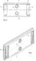
- Each plate stack 4 is formed from a plurality of individual plates 7, for example according to the embodiment of Figures 3 and 4.
- the single plate 7 is substantially rectangular and provided with two inlet openings 7a arranged on their narrow sides.
- each individual plate 7 has in the region of the center of its long sides an outlet opening 7b and an additional opening 7c. How in particular Fig. 3 reveals, the single plate 7 is in terms of their entry, exit and Additional opening 7a, 7b, 7c formed symmetrically to both plate axes.
- each inlet opening is located 7a of the plate stack 4 via a corresponding opening in the supporting wall 2 with the steam supply chamber 1a of the housing 1 in connection.
- steam supplied via the inlet connection 3 enters the channels between the individual plates 7 of each pair of plates are formed. That steam serves to thicken the sugar solution supplied to the housing 1; the residual steam or the condensate is discharged through the outlet openings 7b (see FIG. 3) deducted by a corresponding, formed in the support wall 2 Opening are connected to a condensate line 9.
- the one in the single plates 7 formed additional openings 7c are above a corresponding opening in the support wall 2 with an inert gas line 10 in connection.
- Fig. 1 further shows that the sugar solution the vapor space 1b of the housing 1 is fed through a feed line 11 which is in a juice distributor 12 flows.
- the sugar solution emerges from the underside of this juice distributor 12 in the form of fine rays that hit the top of the top stack of plates 4 hit and stack this plate from top to bottom through those Flow through channels formed by adjacent plate pairs will.
- the sugar solution is through the steam flowing inside the plate stack is thickened.
- the one here emerging vapors emerge from the side as well as above and below Plate stack 4 out. You are at the top of the housing 1 by one Vapor connector 13 deducted.
- the one above the other Supporting wall 2 attached plate stack 4 in particular for cleaning them with the sugar solution loaded channels removed from the support wall 2 are formed by the clamping screws in the exemplary embodiment Clamping elements 5 released and the pressure plates 6 removed, so that the plate stack 4 can be removed from the support wall 2. Since at Embodiment according to Figures 3 and 4, the individual plate pairs exclusively sealed with the help of the clamping elements 5 and the pressure plate 6 are held together is a disassembly of the individual plate stacks 4 possible in pairs of plates, so that the channels acted upon by the sugar solution can be easily cleaned.
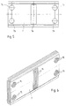
- FIGS. 5 and 6 thus results in a stack of plates 4 from fully welded individual plates 7, which, however, just like the plate stack 4 from the individual plates 7 shown in FIGS. 3 and 4 from the Support wall 2 removed and cleaned outside of the housing 1 can.
- FIG. 7 shows one the first embodiment of Figures 3 and 4 similar training.
- the openings 7a, 7b and 7c of the individual plates 7 become more adjacent Plate pairs through seals 8 compared to that of the sugar solution flowed through channels sealed when the plate pairs using the Clamping elements 5 and the pressure plate 6 releasably attached to the support wall 2 will.
- Fig. 7 shows that it is possible in this embodiment, inside of the inlet openings 7a, guide holes 7d in the individual plates 7 to train. These guide holes 7d are used to weld the plate pairs Individual plates 7 threaded onto the clamping elements 5 so that they Clamping elements 5 also serve as guides for the individual plates 7 when these are releasably attached to the support wall 2.
Landscapes
- Engineering & Computer Science (AREA)
- Chemical & Material Sciences (AREA)
- Physics & Mathematics (AREA)
- Thermal Sciences (AREA)
- Mechanical Engineering (AREA)
- General Engineering & Computer Science (AREA)
- Life Sciences & Earth Sciences (AREA)
- Biochemistry (AREA)
- Organic Chemistry (AREA)
- Heat-Exchange Devices With Radiators And Conduit Assemblies (AREA)
- Hybrid Cells (AREA)
Priority Applications (4)
| Application Number | Priority Date | Filing Date | Title |
|---|---|---|---|
| DK97100494T DK0853224T3 (da) | 1997-01-15 | 1997-01-15 | Varmeveksler |
| EP19970100494 EP0853224B1 (fr) | 1997-01-15 | 1997-01-15 | Echangeur de chaleur |
| DE59705267T DE59705267D1 (de) | 1997-01-15 | 1997-01-15 | Wärmeüberträger |
| ES97100494T ES2167622T3 (es) | 1997-01-15 | 1997-01-15 | Intercambiador de calor. |
Applications Claiming Priority (1)
| Application Number | Priority Date | Filing Date | Title |
|---|---|---|---|
| EP19970100494 EP0853224B1 (fr) | 1997-01-15 | 1997-01-15 | Echangeur de chaleur |
Publications (2)
| Publication Number | Publication Date |
|---|---|
| EP0853224A1 true EP0853224A1 (fr) | 1998-07-15 |
| EP0853224B1 EP0853224B1 (fr) | 2001-11-07 |
Family
ID=8226367
Family Applications (1)
| Application Number | Title | Priority Date | Filing Date |
|---|---|---|---|
| EP19970100494 Expired - Lifetime EP0853224B1 (fr) | 1997-01-15 | 1997-01-15 | Echangeur de chaleur |
Country Status (4)
| Country | Link |
|---|---|
| EP (1) | EP0853224B1 (fr) |
| DE (1) | DE59705267D1 (fr) |
| DK (1) | DK0853224T3 (fr) |
| ES (1) | ES2167622T3 (fr) |
Cited By (6)
| Publication number | Priority date | Publication date | Assignee | Title |
|---|---|---|---|---|
| FR2793875A1 (fr) * | 1999-05-19 | 2000-11-24 | Packinox Sa | Echangeur thermique a plaques |
| EP1098008A1 (fr) * | 1999-11-04 | 2001-05-09 | Balcke-Dürr Energietechnik GmbH | Evaporateur |
| EP1154216A1 (fr) * | 2000-05-11 | 2001-11-14 | Balcke-Dürr Energietechnik GmbH | Dispositif pour chauffage de liquides à la vapeur |
| EP1085285A3 (fr) * | 1999-09-16 | 2002-05-08 | Balcke-Dürr Energietechnik GmbH | Echangeur de chaleur à plaques et évaporateur |
| WO2024146434A1 (fr) * | 2023-01-05 | 2024-07-11 | 法雷奥汽车空调湖北有限公司 | Échangeur de chaleur intermédiaire, ensemble échange de chaleur et circuit de fluide frigorigène |
| CN118912984A (zh) * | 2024-10-10 | 2024-11-08 | 中和能(浙江)科技有限公司 | 一种单板可拆的板式换热器 |
Families Citing this family (1)
| Publication number | Priority date | Publication date | Assignee | Title |
|---|---|---|---|---|
| US12460873B2 (en) * | 2023-10-05 | 2025-11-04 | Rygan Corp. | Heat exchanger, plate element therefor, and method of construction |
Citations (3)
| Publication number | Priority date | Publication date | Assignee | Title |
|---|---|---|---|---|
| FR2523287A1 (fr) * | 1982-03-12 | 1983-09-16 | Lecomte Robert | Echangeur de chaleur de type liquide-gaz en particulier pour la recuperation de la chaleur des fumees |
| EP0729772A2 (fr) * | 1995-03-03 | 1996-09-04 | BDAG Balcke-Dürr Aktiengesellschaft | Evaporateur |
| EP0740949A1 (fr) * | 1995-05-04 | 1996-11-06 | Packinox | Echangeur thermique à plaques |
-
1997
- 1997-01-15 EP EP19970100494 patent/EP0853224B1/fr not_active Expired - Lifetime
- 1997-01-15 ES ES97100494T patent/ES2167622T3/es not_active Expired - Lifetime
- 1997-01-15 DE DE59705267T patent/DE59705267D1/de not_active Expired - Fee Related
- 1997-01-15 DK DK97100494T patent/DK0853224T3/da active
Patent Citations (3)
| Publication number | Priority date | Publication date | Assignee | Title |
|---|---|---|---|---|
| FR2523287A1 (fr) * | 1982-03-12 | 1983-09-16 | Lecomte Robert | Echangeur de chaleur de type liquide-gaz en particulier pour la recuperation de la chaleur des fumees |
| EP0729772A2 (fr) * | 1995-03-03 | 1996-09-04 | BDAG Balcke-Dürr Aktiengesellschaft | Evaporateur |
| EP0740949A1 (fr) * | 1995-05-04 | 1996-11-06 | Packinox | Echangeur thermique à plaques |
Cited By (7)
| Publication number | Priority date | Publication date | Assignee | Title |
|---|---|---|---|---|
| FR2793875A1 (fr) * | 1999-05-19 | 2000-11-24 | Packinox Sa | Echangeur thermique a plaques |
| EP1085285A3 (fr) * | 1999-09-16 | 2002-05-08 | Balcke-Dürr Energietechnik GmbH | Echangeur de chaleur à plaques et évaporateur |
| EP1098008A1 (fr) * | 1999-11-04 | 2001-05-09 | Balcke-Dürr Energietechnik GmbH | Evaporateur |
| US6793770B1 (en) | 1999-11-04 | 2004-09-21 | Balcke-Durr Energietechnik Gmbh | Evaporator |
| EP1154216A1 (fr) * | 2000-05-11 | 2001-11-14 | Balcke-Dürr Energietechnik GmbH | Dispositif pour chauffage de liquides à la vapeur |
| WO2024146434A1 (fr) * | 2023-01-05 | 2024-07-11 | 法雷奥汽车空调湖北有限公司 | Échangeur de chaleur intermédiaire, ensemble échange de chaleur et circuit de fluide frigorigène |
| CN118912984A (zh) * | 2024-10-10 | 2024-11-08 | 中和能(浙江)科技有限公司 | 一种单板可拆的板式换热器 |
Also Published As
| Publication number | Publication date |
|---|---|
| ES2167622T3 (es) | 2002-05-16 |
| DE59705267D1 (de) | 2001-12-13 |
| EP0853224B1 (fr) | 2001-11-07 |
| DK0853224T3 (da) | 2002-02-25 |
Similar Documents
| Publication | Publication Date | Title |
|---|---|---|
| DE60112767T2 (de) | Plattenwärmetauscher | |
| WO2009152830A1 (fr) | Jeu d’adaptation pour un échangeur de chaleur à faisceau tubulaire | |
| EP0256259B1 (fr) | Echangeur de chaleur, en particulier évaporateur pour réfrigérant | |
| EP0109097B2 (fr) | Echangeur de chaleur à plaques | |
| DE69401610T2 (de) | Wärmetauscher | |
| DE19709601A1 (de) | Plattenwärmeübertrager | |
| DE2231112A1 (de) | Rohrverteiler | |
| EP0853224B1 (fr) | Echangeur de chaleur | |
| EP0495184B1 (fr) | Echangeur de chaleur à plaques à écoulement à contre-courant | |
| DE4019991A1 (de) | Kolonnenkoerper zur aufnahme von plattenwaermetauschern | |
| DE2240349B2 (de) | Stuetzkonstruktion fuer waermetauscherrohre | |
| EP1139055B1 (fr) | Echangeur de chaleur à multiples faisceaux de tubes | |
| DD144601A5 (de) | Waermeaustauscher | |
| DE3834941A1 (de) | Waermeaustauscher | |
| EP1738819B1 (fr) | Dispositif pour la purification catalytique de gaz d'échappement | |
| DE3533196C2 (fr) | ||
| DE19605508C2 (de) | Atmosphärischer Gasbrenner für Heizkessel | |
| EP0331067A2 (fr) | Echangeur de masse et/ou de chaleur | |
| DE3538515A1 (de) | Vorrichtung zum kuehlen von heissen, staubbeladenen gasen | |
| DE4020754A1 (de) | Waermetauscher fuer zwei fluessige medien | |
| AT404877B (de) | Gegenstrom-plattenwärmetauscher | |
| DE2617261C2 (de) | Wärmeaustauscher | |
| DE202020106431U1 (de) | Wärmetauschermodul und Wärmetauscher | |
| DE3136866C2 (de) | Röhrenwärmetauscher mit Strömungsleiteinbauten | |
| DE3148102A1 (de) | Waermetauscher |
Legal Events
| Date | Code | Title | Description |
|---|---|---|---|
| PUAI | Public reference made under article 153(3) epc to a published international application that has entered the european phase |
Free format text: ORIGINAL CODE: 0009012 |
|
| 17P | Request for examination filed |
Effective date: 19971218 |
|
| AK | Designated contracting states |
Kind code of ref document: A1 Designated state(s): DE DK ES FR GB IT SE |
|
| AKX | Designation fees paid |
Free format text: DE DK ES FR GB IT SE |
|
| RBV | Designated contracting states (corrected) |
Designated state(s): DE DK ES FR GB IT SE |
|
| 17Q | First examination report despatched |
Effective date: 20000117 |
|
| GRAG | Despatch of communication of intention to grant |
Free format text: ORIGINAL CODE: EPIDOS AGRA |
|
| GRAG | Despatch of communication of intention to grant |
Free format text: ORIGINAL CODE: EPIDOS AGRA |
|
| GRAH | Despatch of communication of intention to grant a patent |
Free format text: ORIGINAL CODE: EPIDOS IGRA |
|
| GRAH | Despatch of communication of intention to grant a patent |
Free format text: ORIGINAL CODE: EPIDOS IGRA |
|
| RAP1 | Party data changed (applicant data changed or rights of an application transferred) |
Owner name: BALCKE-DUERR ENERGIETECHNIK GMBH |
|
| GRAA | (expected) grant |
Free format text: ORIGINAL CODE: 0009210 |
|
| AK | Designated contracting states |
Kind code of ref document: B1 Designated state(s): DE DK ES FR GB IT SE |
|
| REF | Corresponds to: |
Ref document number: 59705267 Country of ref document: DE Date of ref document: 20011213 |
|
| REG | Reference to a national code |
Ref country code: GB Ref legal event code: IF02 |
|
| GBT | Gb: translation of ep patent filed (gb section 77(6)(a)/1977) |
Effective date: 20020114 |
|
| ET | Fr: translation filed | ||
| REG | Reference to a national code |
Ref country code: DK Ref legal event code: T3 |
|
| REG | Reference to a national code |
Ref country code: ES Ref legal event code: FG2A Ref document number: 2167622 Country of ref document: ES Kind code of ref document: T3 |
|
| PLBE | No opposition filed within time limit |
Free format text: ORIGINAL CODE: 0009261 |
|
| STAA | Information on the status of an ep patent application or granted ep patent |
Free format text: STATUS: NO OPPOSITION FILED WITHIN TIME LIMIT |
|
| 26N | No opposition filed | ||
| REG | Reference to a national code |
Ref country code: GB Ref legal event code: 732E |
|
| REG | Reference to a national code |
Ref country code: FR Ref legal event code: TP |
|
| REG | Reference to a national code |
Ref country code: ES Ref legal event code: PC2A |
|
| PGFP | Annual fee paid to national office [announced via postgrant information from national office to epo] |
Ref country code: ES Payment date: 20090122 Year of fee payment: 13 Ref country code: DK Payment date: 20090113 Year of fee payment: 13 |
|
| PGFP | Annual fee paid to national office [announced via postgrant information from national office to epo] |
Ref country code: DE Payment date: 20081229 Year of fee payment: 13 |
|
| PGFP | Annual fee paid to national office [announced via postgrant information from national office to epo] |
Ref country code: GB Payment date: 20090122 Year of fee payment: 13 |
|
| PGFP | Annual fee paid to national office [announced via postgrant information from national office to epo] |
Ref country code: SE Payment date: 20090114 Year of fee payment: 13 Ref country code: IT Payment date: 20090128 Year of fee payment: 13 |
|
| PGFP | Annual fee paid to national office [announced via postgrant information from national office to epo] |
Ref country code: FR Payment date: 20090115 Year of fee payment: 13 |
|
| REG | Reference to a national code |
Ref country code: DK Ref legal event code: EBP |
|
| GBPC | Gb: european patent ceased through non-payment of renewal fee |
Effective date: 20100115 |
|
| EUG | Se: european patent has lapsed | ||
| REG | Reference to a national code |
Ref country code: FR Ref legal event code: ST Effective date: 20100930 |
|
| PG25 | Lapsed in a contracting state [announced via postgrant information from national office to epo] |
Ref country code: FR Free format text: LAPSE BECAUSE OF NON-PAYMENT OF DUE FEES Effective date: 20100201 |
|
| PG25 | Lapsed in a contracting state [announced via postgrant information from national office to epo] |
Ref country code: DE Free format text: LAPSE BECAUSE OF NON-PAYMENT OF DUE FEES Effective date: 20100803 |
|
| PG25 | Lapsed in a contracting state [announced via postgrant information from national office to epo] |
Ref country code: GB Free format text: LAPSE BECAUSE OF NON-PAYMENT OF DUE FEES Effective date: 20100115 |
|
| PG25 | Lapsed in a contracting state [announced via postgrant information from national office to epo] |
Ref country code: DK Free format text: LAPSE BECAUSE OF NON-PAYMENT OF DUE FEES Effective date: 20100131 |
|
| PG25 | Lapsed in a contracting state [announced via postgrant information from national office to epo] |
Ref country code: IT Free format text: LAPSE BECAUSE OF NON-PAYMENT OF DUE FEES Effective date: 20100115 |
|
| REG | Reference to a national code |
Ref country code: ES Ref legal event code: FD2A Effective date: 20111118 |
|
| PG25 | Lapsed in a contracting state [announced via postgrant information from national office to epo] |
Ref country code: ES Free format text: LAPSE BECAUSE OF NON-PAYMENT OF DUE FEES Effective date: 20100116 |
|
| PG25 | Lapsed in a contracting state [announced via postgrant information from national office to epo] |
Ref country code: SE Free format text: LAPSE BECAUSE OF NON-PAYMENT OF DUE FEES Effective date: 20100116 |