EP0853224B1 - Wärmeüberträger - Google Patents
Wärmeüberträger Download PDFInfo
- Publication number
- EP0853224B1 EP0853224B1 EP19970100494 EP97100494A EP0853224B1 EP 0853224 B1 EP0853224 B1 EP 0853224B1 EP 19970100494 EP19970100494 EP 19970100494 EP 97100494 A EP97100494 A EP 97100494A EP 0853224 B1 EP0853224 B1 EP 0853224B1
- Authority
- EP
- European Patent Office
- Prior art keywords
- plate
- heat exchanger
- openings
- plates
- exchanger according
- Prior art date
- Legal status (The legal status is an assumption and is not a legal conclusion. Google has not performed a legal analysis and makes no representation as to the accuracy of the status listed.)
- Expired - Lifetime
Links
Images


Classifications
-
- C—CHEMISTRY; METALLURGY
- C13—SUGAR INDUSTRY
- C13B—PRODUCTION OF SUCROSE; APPARATUS SPECIALLY ADAPTED THEREFOR
- C13B25/00—Evaporators or boiling pans specially adapted for sugar juices; Evaporating or boiling sugar juices
- C13B25/003—Evaporators or boiling pans specially adapted for sugar juices; Evaporating or boiling sugar juices with heating plates
-
- F—MECHANICAL ENGINEERING; LIGHTING; HEATING; WEAPONS; BLASTING
- F28—HEAT EXCHANGE IN GENERAL
- F28D—HEAT-EXCHANGE APPARATUS, NOT PROVIDED FOR IN ANOTHER SUBCLASS, IN WHICH THE HEAT-EXCHANGE MEDIA DO NOT COME INTO DIRECT CONTACT
- F28D9/00—Heat-exchange apparatus having stationary plate-like or laminated conduit assemblies for both heat-exchange media, the media being in contact with different sides of a conduit wall
- F28D9/0006—Heat-exchange apparatus having stationary plate-like or laminated conduit assemblies for both heat-exchange media, the media being in contact with different sides of a conduit wall the plate-like or laminated conduits being enclosed within a pressure vessel
-
- F—MECHANICAL ENGINEERING; LIGHTING; HEATING; WEAPONS; BLASTING
- F28—HEAT EXCHANGE IN GENERAL
- F28F—DETAILS OF HEAT-EXCHANGE AND HEAT-TRANSFER APPARATUS, OF GENERAL APPLICATION
- F28F3/00—Plate-like or laminated elements; Assemblies of plate-like or laminated elements
- F28F3/08—Elements constructed for building-up into stacks, e.g. capable of being taken apart for cleaning
- F28F3/083—Elements constructed for building-up into stacks, e.g. capable of being taken apart for cleaning capable of being taken apart
Definitions
- the invention relates in particular to a steam-heated thickener, Heat exchangers intended for sugar solutions Heat exchange between two separate media with one A plurality of pairs of plates, each consisting of two at their edges circumferentially welded individual plates formed and at least one in a stack of plates arranged with sealed against each other Plate pairs are joined, the one medium through which by the Individual plates formed channels and the other medium through between channels formed adjacent plate pairs flows.
- the invention has for its object to further develop such heat exchangers with the aim of easier maintenance and, if necessary, repair and a modular structure for the purpose of easier adaptation to different circumstances and output sizes.
- the solution to this problem is characterized in that the plate stack is fastened to a supporting wall with openings to the channels for the other medium, dividing the housing into a steam supply space and a vapor space containing the plate stack, the housing having at least one inlet connection and at least one outlet connection for the one acting on the medium formed between adjacent pairs of plates is provided, and that the individual plates are each provided with at least one inlet opening and at least one outlet opening, which correspond to the corresponding openings in the individual plates of the adjacent plate pair to form inflow and outflow connections for the other Medium are connected in a sealed manner.
- the sugar solution thickened by the steam flowing within the plate stack.
- the one here emerging vapors can be from the side as well as above and below emerge from individual stacks of plates. You will be at the top of the Vapor room preferably through a vapor connector from the housing deducted.
- FR-A-2 523 287 was a cross-current operated Plate heat exchanger known in which, for example, the heat emitting Medium is supplied through an opening channels that are separated from one another by a are separated by another channel to which the heat absorbing medium is separated by a further opening is fed. Every second channel is therefore from the heat emitting and the intermediate channels from the heat absorbing Medium flows through. For this it is necessary that the individual plates with corresponding nozzles are provided, which prevent the respective Medium can flow into each channel.
- the disk package from the FR-A-2 523 287 known plate heat exchanger is of a housing surround that has no media-carrying properties. So far acts it is a known heat exchanger, but not one especially as a steam-heated thickener with the heat exchanger Features of EP-A-0 729 772.
- the individual plates to form a pair of plates at their edge with each other are welded all around, it is according to further features of the Invention possible, the individual plates of the plate stack either on the edge of their Weld openings together or by only the individual Seals around the opening to seal against each other, d. H. removable to execute. In addition to a fully welded plate stack, this is also the Production of a plate stack possible, the individual plate pairs can be taken apart for maintenance, for example.
- each individual plate according to another feature of the invention except at least an inlet opening for the steam and at least one outlet opening for the Condensate at least one additional opening for the discharge of inert gases exhibit.
- the connection of adjacent individual plates of the plate stack takes place here also with respect to the additional openings either by welding the Opening edges or by only surrounding the individual opening Seals.
- the single plate is closed two plate axes are symmetrical. This gives the advantage that the plate stack can be made from identical individual plates, so that only one tool is required for the production of the individual plates and for the manufacture of heat exchangers only kept one type of plate in stock must become.
- each individual plate is in the designed essentially rectangular and with two arranged on their narrow sides Entry openings and in the middle of their long sides with one each provided as an outlet or additional opening.
- the plate stack arranged in the housing is in a preferred embodiment the invention in the vertical direction from that of the housing via Einund Medium flows through the outlet port.
- Plate stacks are preferably arranged one above the other at a distance. While the stacks are directly on top of each other, the vapors are on the side must emerge, with stacks lying one above the other at a distance also leave the space between the stacks of vapors.
- the inlet and outlet openings in the supporting wall and, if appropriate, additional openings in the individual plates corresponding openings are provided, there is a particularly simple arrangement of the Plate stack on the supporting wall, the one with the exit and, if necessary Additional openings corresponding openings with a condensate or Inert gas line to be connected.
- Those used to attach the stack of panels to the bulkhead Clamping elements can be arranged outside and / or inside the plate stack become. Furthermore, it is possible according to the invention, the clamping elements in Arrange the area of the openings in the individual panels, creating the possibility arises, these clamping elements also as guides for the individual plates train so that their attachment to the supporting wall is facilitated.
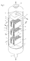
- the heat exchanger is designed as a steam-heated thickener for sugar solutions. It has a housing 1, which is vertical in the exemplary embodiment standing cylindrical drum is designed with an axial direction extending support wall 2 is provided, which the interior of the housing 1 according to FIG. 2 divided into a steam supply space 1a and a vapor space 1b. In the area of the steam supply chamber 1 a, the housing 1 has an inlet connection 3 provided for the steam.
- three plate stacks are on the front of the support wall 2 4 arranged, which in the embodiment of Figures 1 and 2 each by four clamping elements 5 using a pressure plate 6 are attached.
- the three plate stacks 4 are spaced one above the other.
- Each plate stack 4 is formed from a plurality of individual plates 7, for example according to the embodiment of Figures 3 and 4.
- the single plate 7 is substantially rectangular and provided with two inlet openings 7a arranged on their narrow sides.
- each individual plate 7 has in the region of the center of its long sides an outlet opening 7b and an additional opening 7c.
- the single plate 7 is in terms of their entry, exit and Additional opening 7a, 7b, 7c formed symmetrically to both plate axes.
- each inlet opening is located 7a of the plate stack 4 via a corresponding opening in the supporting wall 2 with the steam supply chamber 1a of the housing 1 in connection.
- steam supplied via the inlet connection 3 enters the channels between the individual plates 7 of each pair of plates are formed. That steam serves to thicken the sugar solution supplied to the housing 1; the residual steam or the condensate is discharged through the outlet openings 7b (see FIG. 3) deducted by a corresponding, formed in the support wall 2 Opening are connected to a condensate line 9.
- the one in the single plates 7 formed additional openings 7c are above a corresponding opening in the support wall 2 with an inert gas line 10 in connection.
- Fig. 1 further shows that the sugar solution the vapor space 1b of the housing 1 is fed through a feed line 11 which is in a juice distributor 12 flows.
- the sugar solution emerges from the underside of this juice distributor 12 in the form of fine rays that hit the top of the top stack of plates 4 hit and stack this plate from top to bottom through those Flow through channels formed by adjacent plate pairs become.
- the sugar solution is through the steam flowing inside the plate stack is thickened.
- the one here emerging vapors emerge from the side as well as above and below Plate stack 4 out. You are at the top of the housing 1 by one Vapor connector 13 deducted.
- the one above the other Supporting wall 2 attached plate stack 4 in particular for cleaning them with the sugar solution loaded channels removed from the support wall 2 are formed by the clamping screws in the exemplary embodiment Clamping elements 5 released and the pressure plates 6 removed, so that the plate stack 4 can be removed from the support wall 2. Since at Embodiment according to Figures 3 and 4, the individual plate pairs exclusively sealed with the help of the clamping elements 5 and the pressure plate 6 are held together is a disassembly of the individual plate stacks 4 possible in pairs of plates, so that the channels acted upon by the sugar solution can be easily cleaned.
- FIGS. 5 and 6 thus results in a stack of plates 4 from fully welded individual plates 7, which, however, just like the plate stack 4 from the individual plates 7 shown in FIGS. 3 and 4 from the Support wall 2 removed and cleaned outside of the housing 1 can.
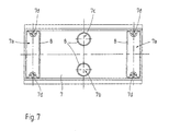
- FIG. 7 shows one the first embodiment of Figures 3 and 4 similar training.
- the openings 7a, 7b and 7c of the individual plates 7 become more adjacent Plate pairs through seals 8 compared to that of the sugar solution flowed through channels sealed when the plate pairs using the Clamping elements 5 and the pressure plate 6 releasably attached to the support wall 2 become.
- Fig. 7 shows that it is possible in this embodiment, inside of the inlet openings 7a, guide holes 7d in the individual plates 7 to train. These guide holes 7d are used to weld the plate pairs Individual plates 7 threaded onto the clamping elements 5 so that they Clamping elements 5 also serve as guides for the individual plates 7 when these are releasably attached to the support wall 2.
Landscapes
- Engineering & Computer Science (AREA)
- Chemical & Material Sciences (AREA)
- Physics & Mathematics (AREA)
- Thermal Sciences (AREA)
- Mechanical Engineering (AREA)
- General Engineering & Computer Science (AREA)
- Life Sciences & Earth Sciences (AREA)
- Biochemistry (AREA)
- Organic Chemistry (AREA)
- Heat-Exchange Devices With Radiators And Conduit Assemblies (AREA)
- Hybrid Cells (AREA)
Description
- Fig. 1
- eine perspektivische Darstellung eines Ausführungsbeispieles eines als dampfbeheizter Eindicker für Zuckerlösungen ausgebildeten Wärmeübertragers,
- Fig. 2
- einen waagerechten Schnitt durch den Wärmeübertrager gemäß der Schnittlinie II-II in Fig. 1,
- Fig. 3
- eine Seitenansicht eines ersten Ausführungsbeispiels einer Einzelplatte mit die einzelnen Öffnungen umgebenden Dichtungen,
- Fig. 4
- eine perspektivische Ansicht eines Plattenstapels, der aus vier Plattenpaaren unter Verwendung der in Fig. 3 gezeigten Einzelplatte hergestellt ist,
- Fig. 5
- ein zweites Ausführungsbeispiel einer im Bereich ihrer Öffnungen zu verschweißenden Einzelplatte anhand einer der Fig. 3 entsprechenden Seitenansicht,
- Fig. 6
- eine perspektivische Darstellung eines aus Einzelplatten gemäß Fig. 5 hergestellten Plattenstapels und
- Fig. 7
- eine Seitenansicht einer dritten Ausführungsform einer Einzelplatte, die mittels im Bereich ihrer Eintrittsöffnungen verlaufender Spannelemente lösbar an einer Tragwand befestigt wird.
- 1
- Gehäuse
- 1a
- Dampfzufuhrraum
- 1b
- Brüdenraum
- 2
- Tragwand
- 3
- Eintrittstutzen
- 4
- Plattenstapel
- 5
- Spannelement
- 6
- Druckplatte
- 7
- Einzelplatte
- 7a
- Eintrittsöffnung
- 7b
- Austrittsöffnung
- 7c
- Zusatzöffnung
- 7d
- Führungsloch
- 8
- Dichtung
- 9
- Kondensatleitung
- 10
- Inertgasleitung
- 11
- Zufuhrleitung
- 12
- Saftverteiler
- 13
- Brüdenstutzen
- 14
- Saftstutzen
- 15
- Schweißnaht
Claims (13)
- Wärmeübertrager für den Wärmeaustausch zwischen zwei voneinander getrennten Medien, insbesondere als dampfbeheizter Eindicker, vorzugsweise für Zuckerlösungen, mit einer Mehrzahl von Plattenpaaren, die jeweils aus zwei an ihrem Rand miteinander umlaufend verschweißten Einzelplatten (7) gebildet und zu mindestens einem in einem Gehäuse (1) angeordneten Plattenstapel (4) mit gegeneinander abgedichteten Plattenpaaren zusammengefügt sind, wobei das eine Medium durch die durch die Einzelplatten (7) gebildeten Kanäle und das andere Medium durch die zwischen benachbarten Plattenpaaren gebildeten Kanäle strömt,
dadurch gekennzeichnet,daß der Plattenstapel (4) an einer das Gehäuse (1) in einen Dampfzuführraum (1a) und einen den Plattenstapel (4) enthaltenden Brüdenraum (1b) unterteilenden Tragwand (2) mit Öffnungen zu den Kanälen für das andere medium befestigt ist, wobei das Gehäuse (1) mit mindestens einem Eintrittstutzen (11) und mindestens einem Austrittstutzen (13, 14) für das eine, die zwischen benachbarten Plattenpaaren gebildeten Kanäle beaufschlagende Medium versehen ist, unddaß die Einzelplatten (7) jeweils mit mindestens einer Eintrittsöffnung (7a) und mindestens einer Austrittsöffnung (7b) versehen sind, die mit den entsprechenden Öffnungen der Einzelplatten (7) des benachbarten Plattenpaares zur Bildung von Zu- und Abströmstutzen für das andere Medium abgedichtet verbunden sind. - Wärmeübertrager nach Anspruch 1, dadurch gekennzeichnet, daß die Einzelplatten (7) des Plattenstapels (4) am Rand ihrer Öffnungen (7a, 7b) miteinander verschweißt sind.
- Wärmeübertrager nach Anspruch 1, dadurch gekennzeichnet, daß die Einzelplatten (7) des Plattenstapels (4) durch ausschließlich die Eintritts- und Austrittsöffnungen Öffnung (7a, 7b) umgebende Dichtungen (8) gegeneinander abgedichtet sind.
- Wärmeübertrager nach mindestens einem der Ansprüche 1 bis 3 als dampfbeheizter Eindicker, dadurch gekennzeichnet, daß jede Einzelplatte (7) außer mindestens einer Eintrittsöffnung (7a) für den Dampf und mindestens einer Austrittsöffnung (7b) für das Kondensat mindestens eine Zusatzöffnung (7c) für den Austritt von Inertgasen aufweist.
- Wärmeübertrager nach mindestens einem der Ansprüche 1 bis 4, dadurch gekennzeichnet, daß die Einzelplatte (7) zu beiden Plattenachsen symmetrisch ausgebildet ist.
- Wärmeübertrager nach Anspruch 4 oder 5, dadurch gekennzeichnet, daß jede Einzelplatte (7) im wesentlichen rechteckig ausgebildet und mit zwei an ihren Schmalseiten angeordneten Eintrittsöffnungen (7a) sowie in der Mitte ihrer Längsseiten mit jeweils einer als Austritts- bzw. Zusatzöffnung (7b bzw. 7c) dienenden Öffnung versehen ist.
- Wärmeübertrager nach mindestens einem der Ansprüche 1 bis 6, dadurch gekennzeichnet, daß der im Gehäuse (1) angeordnete Plattenstapel (4) von dem dem Gehäuse (1) über Ein- und Austrittstutzen (11, 14) zu- bzw. abgeführten Medium in senkrechter Richtung durchströmt wird.
- Wärmeübertrager nach Anspruch 7, dadurch gekennzeichnet, daß mehrere Plattenstapel (4) vorzugsweise im Abstand übereinander im Gehäuse (1) angeordnet sind.
- Wärmeübertrager nach mindestens einem der Ansprüche 1 bis 8, dadurch gekennzeichnet, daß der oder die Plattenstapel (4) mittels Spannelementen (5) und einer Druckplatte (6) an der Tragwand (2) befestigt ist/sind.
- Wärmeübertrager nach Anspruch 1 oder 9, dadurch gekennzeichnet, daß in der Tragwand (2) den Eintritts- und Austrittsöffnungen (7a, 7b) sowie gegebenenfalls Zusatzöffnungen (7c) der Einzelplatten (7) entsprechende Öffnungen vorgesehen sind, von denen die mit den Austritts- und gegebenenfalls Zusatzöffnungen (7b bzw. 7c) korrespondierenden Öffnungen mit einer Kondensat- bzw. Inertgasleitung (9 bzw. 10) verbunden sind.
- Wärmeübertrager nach Anspruch 9, dadurch gekennzeichnet, daß die Spannelemente (5) außerhalb und/oder innerhalb des Plattenstapels (4) angeordnet sind.
- Wärmeübertrager nach Anspruch 4 und 11, dadurch gekennzeichnet, daß die Spannelemente (5) im Bereich der Öffnungen (7a, 7b, 7c) in den Einzelplatten (7) angeordnet sind.
- Wärmeübertrager nach Anspruch 11 oder 12, dadurch gekennzeichnet, daß die Spannelemente (5) als Führungen für die Einzelplatten (7) ausgebildet sind.
Priority Applications (4)
| Application Number | Priority Date | Filing Date | Title |
|---|---|---|---|
| DK97100494T DK0853224T3 (da) | 1997-01-15 | 1997-01-15 | Varmeveksler |
| EP19970100494 EP0853224B1 (de) | 1997-01-15 | 1997-01-15 | Wärmeüberträger |
| DE59705267T DE59705267D1 (de) | 1997-01-15 | 1997-01-15 | Wärmeüberträger |
| ES97100494T ES2167622T3 (es) | 1997-01-15 | 1997-01-15 | Intercambiador de calor. |
Applications Claiming Priority (1)
| Application Number | Priority Date | Filing Date | Title |
|---|---|---|---|
| EP19970100494 EP0853224B1 (de) | 1997-01-15 | 1997-01-15 | Wärmeüberträger |
Publications (2)
| Publication Number | Publication Date |
|---|---|
| EP0853224A1 EP0853224A1 (de) | 1998-07-15 |
| EP0853224B1 true EP0853224B1 (de) | 2001-11-07 |
Family
ID=8226367
Family Applications (1)
| Application Number | Title | Priority Date | Filing Date |
|---|---|---|---|
| EP19970100494 Expired - Lifetime EP0853224B1 (de) | 1997-01-15 | 1997-01-15 | Wärmeüberträger |
Country Status (4)
| Country | Link |
|---|---|
| EP (1) | EP0853224B1 (de) |
| DE (1) | DE59705267D1 (de) |
| DK (1) | DK0853224T3 (de) |
| ES (1) | ES2167622T3 (de) |
Cited By (1)
| Publication number | Priority date | Publication date | Assignee | Title |
|---|---|---|---|---|
| EP4534940A3 (de) * | 2023-10-05 | 2025-04-30 | Rygan Corp. | Wärmetauscher, plattenelement dafür und verfahren zur konstruktion |
Families Citing this family (6)
| Publication number | Priority date | Publication date | Assignee | Title |
|---|---|---|---|---|
| FR2793875B1 (fr) * | 1999-05-19 | 2001-08-03 | Packinox Sa | Echangeur thermique a plaques |
| DE19944426C2 (de) * | 1999-09-16 | 2003-01-09 | Balcke Duerr Energietech Gmbh | Plattenwärmetauscher und Verdampfer |
| DE59909532D1 (de) * | 1999-11-04 | 2004-06-24 | Balcke Duerr Energietech Gmbh | Verdampfer |
| DE50001791D1 (de) * | 2000-05-11 | 2003-05-22 | Balcke Duerr Energietech Gmbh | Dampfbeheitzter Flüssigkeitserwärmer |
| CN118293591A (zh) * | 2023-01-05 | 2024-07-05 | 法雷奥汽车空调湖北有限公司 | 中间热交换器及热交换组件 |
| CN118912984B (zh) * | 2024-10-10 | 2025-02-18 | 浙江君华智慧物联科技有限公司 | 一种单板可拆的板式换热器 |
Family Cites Families (3)
| Publication number | Priority date | Publication date | Assignee | Title |
|---|---|---|---|---|
| FR2523287A1 (fr) * | 1982-03-12 | 1983-09-16 | Lecomte Robert | Echangeur de chaleur de type liquide-gaz en particulier pour la recuperation de la chaleur des fumees |
| DE29503589U1 (de) * | 1995-03-03 | 1995-04-27 | Balcke Duerr Ag | Verdampfer |
| FR2733823B1 (fr) * | 1995-05-04 | 1997-08-01 | Packinox Sa | Echangeur thermique a plaques |
-
1997
- 1997-01-15 EP EP19970100494 patent/EP0853224B1/de not_active Expired - Lifetime
- 1997-01-15 ES ES97100494T patent/ES2167622T3/es not_active Expired - Lifetime
- 1997-01-15 DE DE59705267T patent/DE59705267D1/de not_active Expired - Fee Related
- 1997-01-15 DK DK97100494T patent/DK0853224T3/da active
Cited By (1)
| Publication number | Priority date | Publication date | Assignee | Title |
|---|---|---|---|---|
| EP4534940A3 (de) * | 2023-10-05 | 2025-04-30 | Rygan Corp. | Wärmetauscher, plattenelement dafür und verfahren zur konstruktion |
Also Published As
| Publication number | Publication date |
|---|---|
| ES2167622T3 (es) | 2002-05-16 |
| DE59705267D1 (de) | 2001-12-13 |
| EP0853224A1 (de) | 1998-07-15 |
| DK0853224T3 (da) | 2002-02-25 |
Similar Documents
| Publication | Publication Date | Title |
|---|---|---|
| EP2304370B1 (de) | Umrüstsatz für einen rohrbündelwärmetauscher | |
| EP0109097B2 (de) | Plattenförmiger Wärmetauscher | |
| EP0256259B1 (de) | Wärmetauscher, insbesondere Kältemittel-Verdampfer | |
| DE10197019B4 (de) | Vorrichtung mit einem röhrenförmigen Filterelement und einer Komponente zum Halten eines Filterelementes, Plattenwärmetauscher mit dieser Vorrichtung | |
| EP0853224A1 (de) | Wärmeüberträger | |
| DE4019991A1 (de) | Kolonnenkoerper zur aufnahme von plattenwaermetauschern | |
| WO2016131787A1 (de) | Rohrbündelwärmeübertrager mit sequentiell angeordneten rohrbündelkomponenten | |
| EP1139055B1 (de) | Mehrfachrohrbündel-Wärmeaustauscher | |
| DD144601A5 (de) | Waermeaustauscher | |
| EP0495184A1 (de) | Plattenwärmetauscher für im Gegenstrom geführte Medien | |
| DE3834941A1 (de) | Waermeaustauscher | |
| EP0223912B1 (de) | Vorrichtung zum Kühlen von heissen, staubbeladenen Gasen | |
| EP0331067A2 (de) | Stoff- und/oder Wärmetauscher | |
| DE10250287C1 (de) | Wärmetauscher, insbesondere für eine Heiz- und/oder Klimaeinrichtung eines Kraftfahzeuges | |
| DE602004007029T2 (de) | Katalytischer reaktor unter pseudo-isothermischen bedingungen | |
| DE4239798A1 (de) | ||
| DE2034353A1 (de) | Mit Lochern versehene Anordnungen | |
| EP3916334A1 (de) | Kühleinrichtung für eine kraftfahrzeugbatterie | |
| DE202020106431U1 (de) | Wärmetauschermodul und Wärmetauscher | |
| DE4020754A1 (de) | Waermetauscher fuer zwei fluessige medien | |
| DE3148102A1 (de) | Waermetauscher | |
| DE3136866C2 (de) | Röhrenwärmetauscher mit Strömungsleiteinbauten | |
| DE4223699A1 (de) | Wärmetauscher | |
| EP0394758A2 (de) | Wärmetauscher | |
| EP1530703A1 (de) | Wärmeübertrager |
Legal Events
| Date | Code | Title | Description |
|---|---|---|---|
| PUAI | Public reference made under article 153(3) epc to a published international application that has entered the european phase |
Free format text: ORIGINAL CODE: 0009012 |
|
| 17P | Request for examination filed |
Effective date: 19971218 |
|
| AK | Designated contracting states |
Kind code of ref document: A1 Designated state(s): DE DK ES FR GB IT SE |
|
| AKX | Designation fees paid |
Free format text: DE DK ES FR GB IT SE |
|
| RBV | Designated contracting states (corrected) |
Designated state(s): DE DK ES FR GB IT SE |
|
| 17Q | First examination report despatched |
Effective date: 20000117 |
|
| GRAG | Despatch of communication of intention to grant |
Free format text: ORIGINAL CODE: EPIDOS AGRA |
|
| GRAG | Despatch of communication of intention to grant |
Free format text: ORIGINAL CODE: EPIDOS AGRA |
|
| GRAH | Despatch of communication of intention to grant a patent |
Free format text: ORIGINAL CODE: EPIDOS IGRA |
|
| GRAH | Despatch of communication of intention to grant a patent |
Free format text: ORIGINAL CODE: EPIDOS IGRA |
|
| RAP1 | Party data changed (applicant data changed or rights of an application transferred) |
Owner name: BALCKE-DUERR ENERGIETECHNIK GMBH |
|
| GRAA | (expected) grant |
Free format text: ORIGINAL CODE: 0009210 |
|
| AK | Designated contracting states |
Kind code of ref document: B1 Designated state(s): DE DK ES FR GB IT SE |
|
| REF | Corresponds to: |
Ref document number: 59705267 Country of ref document: DE Date of ref document: 20011213 |
|
| REG | Reference to a national code |
Ref country code: GB Ref legal event code: IF02 |
|
| GBT | Gb: translation of ep patent filed (gb section 77(6)(a)/1977) |
Effective date: 20020114 |
|
| ET | Fr: translation filed | ||
| REG | Reference to a national code |
Ref country code: DK Ref legal event code: T3 |
|
| REG | Reference to a national code |
Ref country code: ES Ref legal event code: FG2A Ref document number: 2167622 Country of ref document: ES Kind code of ref document: T3 |
|
| PLBE | No opposition filed within time limit |
Free format text: ORIGINAL CODE: 0009261 |
|
| STAA | Information on the status of an ep patent application or granted ep patent |
Free format text: STATUS: NO OPPOSITION FILED WITHIN TIME LIMIT |
|
| 26N | No opposition filed | ||
| REG | Reference to a national code |
Ref country code: GB Ref legal event code: 732E |
|
| REG | Reference to a national code |
Ref country code: FR Ref legal event code: TP |
|
| REG | Reference to a national code |
Ref country code: ES Ref legal event code: PC2A |
|
| PGFP | Annual fee paid to national office [announced via postgrant information from national office to epo] |
Ref country code: ES Payment date: 20090122 Year of fee payment: 13 Ref country code: DK Payment date: 20090113 Year of fee payment: 13 |
|
| PGFP | Annual fee paid to national office [announced via postgrant information from national office to epo] |
Ref country code: DE Payment date: 20081229 Year of fee payment: 13 |
|
| PGFP | Annual fee paid to national office [announced via postgrant information from national office to epo] |
Ref country code: GB Payment date: 20090122 Year of fee payment: 13 |
|
| PGFP | Annual fee paid to national office [announced via postgrant information from national office to epo] |
Ref country code: SE Payment date: 20090114 Year of fee payment: 13 Ref country code: IT Payment date: 20090128 Year of fee payment: 13 |
|
| PGFP | Annual fee paid to national office [announced via postgrant information from national office to epo] |
Ref country code: FR Payment date: 20090115 Year of fee payment: 13 |
|
| REG | Reference to a national code |
Ref country code: DK Ref legal event code: EBP |
|
| GBPC | Gb: european patent ceased through non-payment of renewal fee |
Effective date: 20100115 |
|
| EUG | Se: european patent has lapsed | ||
| REG | Reference to a national code |
Ref country code: FR Ref legal event code: ST Effective date: 20100930 |
|
| PG25 | Lapsed in a contracting state [announced via postgrant information from national office to epo] |
Ref country code: FR Free format text: LAPSE BECAUSE OF NON-PAYMENT OF DUE FEES Effective date: 20100201 |
|
| PG25 | Lapsed in a contracting state [announced via postgrant information from national office to epo] |
Ref country code: DE Free format text: LAPSE BECAUSE OF NON-PAYMENT OF DUE FEES Effective date: 20100803 |
|
| PG25 | Lapsed in a contracting state [announced via postgrant information from national office to epo] |
Ref country code: GB Free format text: LAPSE BECAUSE OF NON-PAYMENT OF DUE FEES Effective date: 20100115 |
|
| PG25 | Lapsed in a contracting state [announced via postgrant information from national office to epo] |
Ref country code: DK Free format text: LAPSE BECAUSE OF NON-PAYMENT OF DUE FEES Effective date: 20100131 |
|
| PG25 | Lapsed in a contracting state [announced via postgrant information from national office to epo] |
Ref country code: IT Free format text: LAPSE BECAUSE OF NON-PAYMENT OF DUE FEES Effective date: 20100115 |
|
| REG | Reference to a national code |
Ref country code: ES Ref legal event code: FD2A Effective date: 20111118 |
|
| PG25 | Lapsed in a contracting state [announced via postgrant information from national office to epo] |
Ref country code: ES Free format text: LAPSE BECAUSE OF NON-PAYMENT OF DUE FEES Effective date: 20100116 |
|
| PG25 | Lapsed in a contracting state [announced via postgrant information from national office to epo] |
Ref country code: SE Free format text: LAPSE BECAUSE OF NON-PAYMENT OF DUE FEES Effective date: 20100116 |