EP0853260B1 - Cartouche de dévelppateur et appareil de remplissage de développateur - Google Patents
Cartouche de dévelppateur et appareil de remplissage de développateur Download PDFInfo
- Publication number
- EP0853260B1 EP0853260B1 EP98100445A EP98100445A EP0853260B1 EP 0853260 B1 EP0853260 B1 EP 0853260B1 EP 98100445 A EP98100445 A EP 98100445A EP 98100445 A EP98100445 A EP 98100445A EP 0853260 B1 EP0853260 B1 EP 0853260B1
- Authority
- EP
- European Patent Office
- Prior art keywords
- toner
- container
- cylindrical
- opening
- container body
- Prior art date
- Legal status (The legal status is an assumption and is not a legal conclusion. Google has not performed a legal analysis and makes no representation as to the accuracy of the status listed.)
- Expired - Lifetime
Links
Images


Classifications
-
- G—PHYSICS
- G03—PHOTOGRAPHY; CINEMATOGRAPHY; ANALOGOUS TECHNIQUES USING WAVES OTHER THAN OPTICAL WAVES; ELECTROGRAPHY; HOLOGRAPHY
- G03G—ELECTROGRAPHY; ELECTROPHOTOGRAPHY; MAGNETOGRAPHY
- G03G15/00—Apparatus for electrographic processes using a charge pattern
- G03G15/06—Apparatus for electrographic processes using a charge pattern for developing
- G03G15/08—Apparatus for electrographic processes using a charge pattern for developing using a solid developer, e.g. powder developer
- G03G15/0822—Arrangements for preparing, mixing, supplying or dispensing developer
- G03G15/0865—Arrangements for supplying new developer
- G03G15/0867—Arrangements for supplying new developer cylindrical developer cartridges, e.g. toner bottles for the developer replenishing opening
- G03G15/0868—Toner cartridges fulfilling a continuous function within the electrographic apparatus during the use of the supplied developer material, e.g. toner discharge on demand, storing residual toner, acting as an active closure for the developer replenishing opening
-
- G—PHYSICS
- G03—PHOTOGRAPHY; CINEMATOGRAPHY; ANALOGOUS TECHNIQUES USING WAVES OTHER THAN OPTICAL WAVES; ELECTROGRAPHY; HOLOGRAPHY
- G03G—ELECTROGRAPHY; ELECTROPHOTOGRAPHY; MAGNETOGRAPHY
- G03G2215/00—Apparatus for electrophotographic processes
- G03G2215/06—Developing structures, details
- G03G2215/066—Toner cartridge or other attachable and detachable container for supplying developer material to replace the used material
- G03G2215/0663—Toner cartridge or other attachable and detachable container for supplying developer material to replace the used material having a longitudinal rotational axis, around which at least one part is rotated when mounting or using the cartridge
- G03G2215/0665—Generally horizontally mounting of said toner cartridge parallel to its longitudinal rotational axis
- G03G2215/0668—Toner discharging opening at one axial end
-
- G—PHYSICS
- G03—PHOTOGRAPHY; CINEMATOGRAPHY; ANALOGOUS TECHNIQUES USING WAVES OTHER THAN OPTICAL WAVES; ELECTROGRAPHY; HOLOGRAPHY
- G03G—ELECTROGRAPHY; ELECTROPHOTOGRAPHY; MAGNETOGRAPHY
- G03G2215/00—Apparatus for electrophotographic processes
- G03G2215/06—Developing structures, details
- G03G2215/066—Toner cartridge or other attachable and detachable container for supplying developer material to replace the used material
- G03G2215/0685—Toner cartridge or other attachable and detachable container for supplying developer material to replace the used material fulfilling a continuous function within the electrographic apparatus during the use of the supplied developer material, e.g. toner discharge on demand, storing residual toner, not acting as a passive closure for the developer replenishing opening
-
- Y—GENERAL TAGGING OF NEW TECHNOLOGICAL DEVELOPMENTS; GENERAL TAGGING OF CROSS-SECTIONAL TECHNOLOGIES SPANNING OVER SEVERAL SECTIONS OF THE IPC; TECHNICAL SUBJECTS COVERED BY FORMER USPC CROSS-REFERENCE ART COLLECTIONS [XRACs] AND DIGESTS
- Y10—TECHNICAL SUBJECTS COVERED BY FORMER USPC
- Y10S—TECHNICAL SUBJECTS COVERED BY FORMER USPC CROSS-REFERENCE ART COLLECTIONS [XRACs] AND DIGESTS
- Y10S222/00—Dispensing
- Y10S222/01—Xerography
Definitions
- This invention relates to a developing apparatus for electrophotographic recording, and in particular to a toner container which contains toner in its cylinder-shaped container body and discharges the toner with rotation, and a toner replenishing device which is fitted with the container and replenishes toner therein to a toner storing portion by rotating the container.
- This type of device has such advantage that any means for preventing the aforesaid excessive replenishment is not necessary, because the toner container is attached to the apparatus mainframe at all time, and it enables a timely replenishment of toner to the toner storing portion by rotating the toner container on ocasion that the toner amount in the storing portion decreases.
- the function is effected by mating the toner discharge opening provided at the end surface of the toner container with the toner receiving opening provided at the end surface of the toner storing portion, so that the exact positioning of the above-mentioned discharge opening and receiving opening is required.
- toner is easy to leak from the joint portion of the toner discharging opening and the toner receiving opening on exchanging the toner container.
- the aforesaid toner container and the aforesaid toner replenishing device to be fitted with the toner container have many subjects to be considered such as how to feed efficiently the toner in its container to the toner storing portion.
- EP-A 0 604 999 discloses a cylindrical toner container used in copiers.
- the toner container body is provided with spiral ribs on the interior circumferential surface which are suitable to convey the toner towards the discharging end by the rotation of the whole container.
- a shutter mechanism inside the container which automatically opens or closes the discharge mouth during mounting and dismounting of the toner bottle.
- the rigid shutter In order to close the discharge mouth the rigid shutter has to be manufactured with care.
- it has to be installed inside the container together with biasing means for moving the shutter against the discharged mouth.
- US-4,937,265 relates to a different type of toner container with a simplified shutter mechanism compared to EP-A-0 604 999,
- a movable rigid sleeve member is movable in the axial direction provided around the end section of the toner container.
- the sleeve is biased by a biasing means, for example a spring.
- a biasing means for example a spring.
- a subject of this invention is to solve the aforesaid problems concerning the toner container and the toner replenishing device which supplies the toner from said container to the developing means.
- the toner container of this invention to solve the above-mentioned problems is defined according to claim 1.
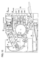
- This color printer is a color image forming apparatus which has a mode of operation as the following: color images formed on the image forming member with one color image superposed on another are transferred to a sheet of trasfer paper at a time to form a full color image at the transfer station, and then it is picked off from the surface of the image forming member.
- Fig. 1 10 is a photoreceptor drum, tne image forming member, composed of an OPC-photoreceptor (organic photoconductor) coated on a drum-shaped base member, which is grounded and driven clockwise as shown in the figure.
- 11 is a scorotron charging device which gives the peripheral surface of the photoreceptor drum a uniform electrostatic charge of a high potential V H with a grid which is kept at a grid potential V G and a corona discharging of a corona discharging wire.
- the charge on the peripheral surface of the photoreceptor is elimimated by exposure to PCL (pre-charging lamp) 12 composed of a photodiode or other proper means in order to elimimate the memory effect of the photoreceptor due to previous printings.
- PCL pre-charging lamp
- the imagewise exposure process based on the image signal is done by the imagewise exposure means 13.
- the main-scanning is done as the following: the light beam emitted from the light source of a laser diode goes through a rotating polygon mirror 131, an f ⁇ lens 132, and a cylindrical lens 133, with its path deflected by a reflection mirror 134, reaches to the surface of the photoreceptor; thus the latent image is formed together with the rotation of the photoreceptor drum 10 (sub-scanning).
- the light is emitted corresponding to the letter part of the original document, so the reversal latent image is formed, in which the potential on the photoreceptor surface corresponding to the letter part is made low as V L .
- a developing apparatus 20 composed of the developing units 20Y, 20M, 20C, and 20K, each having inside a two-component developer composed of one of the toners of yellow (Y), magenta (M), cyan (C), and black (K) respectively and carrier material.
- the yellow, the first color, development is done with a rotating developer carring member (developing sleeve) 21 which has magnets inside and holds the developer.
- the developer is composesd of carrier beads, each of them composed of a ferrite core and a coated layer of insulating resin on it, and the toner particles, each of them composed of polyester resin as main material, a pigment corresponding to the color, and a charge control agent, micro-particles of silica or tatium oxide adhering on it, forms a layer with a thickness between 100 and 600 ⁇ m, regulated with a layer forming means, and is carried to the developing region.
- the spacing from the developing sleeve 21 to the photoreceptor drum 10 at the developing region is 0.2 - 1.0 mm, which is a little larger than the developer layer thickness, and an AC bias voltage V AC and a DC bias voltage V DC overlapped on it is applied to the spacing. Because the DC bias V DC , high potential V H , and the toner charge has the same polarity, the toner particles which are given the chance of taking off from the carrier beads by the AC bias V AC will not deposit on the area having the high potential V H which is higher than the DC bias V DC , but deposit on the area having the low potential VL which is lower than the DC bias V DC to make a visible image (reversal development).
- the second color magenta image forming process starts. Again the uniform charging with the scorotron chargiing device 11 is done to form the latent image corresponding to the image data of the second color using the imagewise exposure means 13.
- the charge elimimation by PCL 12, which was made in the first color image forming process, is not practised this time in order to prevent the toner scattering due to the sudden lowering of the potential of neighboring area.
- the latent image is formed just like the first color and developed, but on those areas where the first color toner particles have been deposited, due to the light shielding by the deposited toner particles and the charge of the toner particles which they have originally, the latent image of potential V M ' is formed and developed in accordance with the potential difference between the DC bias V DC and the potential V M '.
- the image forming process like that for the second color magenta is carried out; the four color visible image is formed on the peripheral surface of the photoreceptor drum 10.
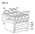
- the toner replenishing device 40 which replenishes the fresh toner of each color controlled to each of the aforesaid developing units 20Y, 20M, 20C, and 20K, is composed of a plurality of the container mounting portions 41Y, 41M, 41C, and 41K, to each of which each of the toner containers (hereinafter refered to as the containers) 30Y, 30M, 30C, and 30K are able to be mounted or dismounted respectively, a plurality of the toner storing portions 42Y, 42M, 42C, and 42K, which store temporarily the toners in said container 30Y, 30M, 30C, and 30K, and a plurality of the toner feeding portions 43Y, 43M, 43C, and 43K, which feed the toners in said toner storing portions to the aforesaid developing units 20Y, 20M, 20C, and 20K.
- a sheet of transfer material (transfer paper etc), which is conveyed out from the paper feeding casette 50 with a half-moon-shaped roller 51, goes through a pair of paper feeding rollers 52 and 53 and stops once in the vicinity of a registration roller pair 54, and is fed to the transfer region with the rotation of the registration roller pair 54 at the moment of the proper timing of the transfer.
- the transfer means 60 is pressed to contact the periphery of the photoreceptor drum 10 synchronized with the transfer timing, hold the fed transfer material sheet p to contact the drum to transfer the multicolored image at a time.
- the transfer material sheet p is processed by the pick-off means 61 to eliminate the charge on it, picked off from the peripheral surface of the photoreceptor drum 10, conveyed to the fixing apparatus 70, where the toner is fused by the heating and pressing with the heat roller (upper roller) 71 and the press roller (lower roller) 72, then discharged onto the receiving tray 83 provided out side the printer body by the paper ejecting rollers 81 and 82.
- the aforesaid transfer means 60 is retracted apart from the photoreceptor periphery after the passing through of the transfer sheet p to be ready for the next toner image forming.
- the photoreceptor drum 10 from which the transfer sheet p is picked off is subjected to the charge elimimation process by the charge eliminating device 14, the residual toner particles on it removed to clean its surface by pressing the blade 151 of the cleaning apparatus 15, is again subjected to the charge elimination by the aforesaid PCL 12 and charging by the scorotron charging device 11 to enter into the next image forming process. Further, the afore said blade 151 moves to be retracted from the photoreceptor periphery immediately after the cleaning of the photoreceptor surface. The waste toner scooped off by the blade 151 into the cleaning apparatus 15 is discharged with the screw 152 and then stored in the collecting container for the waste toner which is not shown in the drawings.
- Fig. 2 is a perspective view showing a plurality of the toner containers 30Y, 30M, 30C, and 30K, a plurality of the toner storing portions 42Y, 42M, 42C, and 42K, and a part of plural developing units 20Y, 20M, 20C, and 20K.
- Each of the container mounting portions 41Y, 41M, 41C, and 41K has each of the four toner containers 30Y, 30M, 30C, and 30K respectively placed parallelly on about the same plane and enables them to be mounted or dismounted.
- FIG. 3 is a partial cross-sectional side view of the container 30;
- Fig. 4 is an exploded side view of said container; and
- Fig. 5 is an exploded perspective view of said container.
- the container 30 is composed of a cylindrical container body 31 containing the toner inside, a fixed cover 32 fixed said container body 31, and a container opening-or-closing cover 33 which is capable of expansion and contraction.
- a guide portion (toner conducting portion) consisting of a coil-shaped protrusion 311 is formed on the inner surface of said container body 31, and the toner contained in the container body 31 is guided along the coil-shaped protrusion 311 to move to the direction of the opening 312.
- 313 is an engaging portion of a V-shaped groove provided on the cylinder surface in the vicinity of said opening 312, fitted closely with an engaging portion 322 of convex shape provided in the vicinity of an opening 321 of said fixed cover 32, which will be explained later, to make both engaging portion unite, so as to fix the opening 312 and the opening 321 of the fixed cover 32.
- an opening 321 which is opposite to the opening of the aforesaid container body 31 and the engaging portion 322 of convex shape provided in the vicinity of the opening 321, and by joining and fixing the opening 312 of the container body 31, the both openings 312 and 321 communicate with each other.
- a projected portion At the approximately central part of the other side (left-hand side) of the fixed cover 32 is formed a projected portion.
- the bumping portion 323 at the extreme end surface of said projected portion contacts with an opening-or-closing cover of the container-mounting portion 41, which will be explained later.
- a plurality of openings (openings for replenishing) 324 On the outer peripheral surface of said projected portion is provided through its wall, a plurality of openings (openings for replenishing) 324, for the purpose of discharging the toner in the aforesaid container body 31 to accumulate it in the toner storing portion of the toner replenishing device 40, which will be explained later.
- the scooping-up portion (paddle) 325 composed of 2 ⁇ 4 plate members to scrape up the toner above the center axis of rotation R of the container 30 and the toner guiding portion 326 made of sloping surface to move-to-guide the toner scooped up by said scooping-up portion 325 to the aforesaid opening 324.
- protruded claw portions are formed at three points.
- the first protruded claw portion 327 provided in the vicinity of the aforesaid bumping portion 323 of the projected portion engages with an engaging portion 331 provided in the vicinity of the left end portion, with regard to the drawing, of the aforesaid container opening-or-closing cover 33, being able to hold or disengage with the engaging portion 331.
- the second protruded claw portion 328 is fixed to engage with an engaging portion 332 provided in the vicinity of right end portion, with regard to the drawing, of the aforesaid container opening-or-closing cover 33.
- the third protruded claw portion 329 engages with a container-slipping-off preventing portion 444 of the driving-force transmitting member 44, which will be explained later, being able to engage or disengage with the preventing portion 444.
- the above-mentioned engaging portion 331 provided in the vicinity of the left end portion, with regard to the drawing, of the aforesaid container opening-or-closing cover 33 is able to be engaged or disengaged with the aforesaid first protruded claw portion 327.
- the middle part of said container opening-or-closing cover 33 is formed like a bellow and is capable of expansion and contraction in the direction of the center axis of rotation.
- Said container opening-or-closing cover 33 is formed like a bellow by blow molding method, and is fixed (fused to bond) to the aforesaid second protruded claw portion 328 by ultrasonic bonding. This bonding may be made by an adhesive.
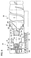
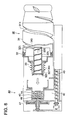
- Fig. 6 is a cross-sectional view showing the aforesaid container 30 before mounting to the container mounting portion 41 of the toner replenishing device 40, that is, as it is spaced apart from the container mounting portion 41; and Fig. 7 is a cross-sectional view of the container 30, the container mounting portion 41, the toner storing portion 42, and the toner feeding portion 43, with said container mounted to the container mounting portion 41.
- the driving-force transmitting member 44 is supported, being capable of rotation, with two parallel upright wall 421 and 422 making up the aforesaid toner storing portion (toner hopper) 42.
- the opening-or-closing cover 45 of the toner-replenishing device is placed and urged with a coil spring 46.
- the container-slipping-off preventing portion 444 is composed of a plurality of arms projected from the right-hand side, with regard to the drawing, of the driving-force transmitting member 44, each of the arms having an engaging claw at the end portion.
- Said container-slipping-off preventing portion 444 engages with the aforesaid third protruded claw portion 329 of the container 30, being capable of engaging and disengaging. Further, at the approximately central part, with regard to the direction of the center axis of ratation, of the driving-force transmitting member 44, a pluralty of openings (toner discharging openings) 441 is provided through the peripheral wall. Furthermore, at the shaft part in the neighborhood of the left-hand side, with ragard to the drawing, of said driving-force transmitting member 44 , the container rotating gear 47 is fixed. Said container rotating gear 47 is driven to ratate with a drive source which is not showh in the drawings.
- the aforesaid container is held by the container mounting portion 41 to be guided on its guide platform 411 to the left direction, with regard to the drawing, until the bumping portion 323 at the extreme end of the container 30 contacts with the right-hand side surface of the aforesaid opening-or-closing cover 45 of the toner replenishing device.
- the opening-or-closing cover 45 of the toner replenishing device is compressed against the force of the coil spring 46, gradually to open the openings (toner discharging openings) 441; when the aforesaid driving-force transmitting member 44 engages with the the third protruded claw portion 329 to be joined to it, the opening 441 comes to the full-open state.
- the bumping portion 323 of the aforesaid container opening-or-closing cover 33 capable of expansion and contraction bumps the inner wall 442 of the aforesaid driving-force transmitting member 44, prevented from going forward, and upon further moving of the container, the engaging portion 331 at the extreme end of the container opening-or-closing cover 33 disengages from the first protruded claw portion 327 at the extreme end of the container 30, to gradually open the openings (openings for replenishing) 324 on the side of the container 30; and at last when the aforesaid driving-force transmitting member 44 engages with the third protruded claw portion 329 to be joined to it, the openings 324 comes to the full-open state.
- the aforesaid container rotating gear is fixed to make them united.
- the central portion of the shaft of the driving-force transmitting member 44 is hollow, a through hole 446 being formed. Said through hole 446 is made in order that when the container 30 is mounted to the container mounting portion 41, the air in the opening-or-closing cover 45 for the toner replenishing device, compressed by the bumping portion 323 at the end of the container 30, may exhaust to the outside of the toner replenishing device. Accordingly, because the air flow doesnot come into the toner hopper when the container is being mounted and the opening-or-closing cover 45 for the toner replenishing device is being opened, the toner in the hopper will never be scattered.
- the aforesaid openings 324 on the side of the container 30 and the opening 441 on the side of the toner replenishing device 40 are brought into the state of being open to each other.
- the container 30 and the driving-force transmitting member 44 which are united with the gear are driven to rotate as a united body; thus the toner contained in the container body 31 of the container 30 is propelled with the coil-shaped protrusion 311 to the direction of the opening 312, then scooped upward by the scooping-up portion (paddle) 325, next sliding down the slope of the toner guiding portion 326 by gravity to be ejected out of the openings 324, and further, passing through the openings (toner discharging openings) 441 of the driving-force transmitting member 44, received in the hopper of the toner storing portion 42.
- the amount of the toner received in said toner storing portion 42 is detected by a photo-detector means, and when it reaches to the predetermined value, the driving of drive source is stopped to cease the replenishing of the toner from the container 30.
- the toner received in the hopper of the toner storing portion 42 is fed into the feeding screw 431 fixed to the feeding-screw gear connected to a drive source, which is not shown in the drawing, conveyed in the toner feeding portion 43, and is replenished to the aforesaid developing unit 20.
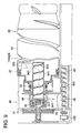
- Fig. 8 and Fig. 9 are cross-sectional views showing the second example of practice of this invention
- Fig. 8 is a cross-sectional view showing the container 30 before mounting to the container mounting portion 41 of the toner replenishing device 40, that is, as it is spaced apart from the container mounting portion 41
- Fig. 9 shows a cross-sectional view of said container 30 as it is mounted to the toner replenishing device 40.
- the toner replenishing device in this mode of practice of the invention has the same construction as that shown in the above-described Fig. 3 - Fig. 7, and only the container 30 has a different construction. Further, the same marks are used for the matters in Fig. 8 and Fig. 9 too, as long as they have the same function as those in said Fig. 3 - Fig. 7. Furthermore, only the different points from the aforesaid example of practice will be explained.
- the toner discharging portion 341 having a hollow cylinder shape is formed unitedly.
- a coil-shaped protrusion 342 is formed.
- a toner introducing opening 343 is provided through its wall.
- the toner discharging opening 344 is provided through its wall. Further, in the vicinity of the aforesaid toner introducing opening 343 inside the aforesaid fixed cover 32, the scooping-up portion (paddle) 325 is formed unitedly.
- the toner contained in the container body 31 of said container 30 is propelled by the coil-shaped protrusion 311 to the direction of the opening 312, then scooped upward by the scooping-up portion (paddle) 325, next sliding down the slope of the scooping-up portion 325 by gravity to be introduced through the toner introducing opening 343 into the toner discharging portion 341 having a hollow cylinder shape, wherein the toner moves to the left direction, with regard to the drawing, guided by the coil-shaped protrusion 342 along the center axis, then discharged from the toner discharging opening 344 in the opened state as the container opening-or-closing cover 33 has already been retracted; finally the toner passes through the opening 441 on the side of the aforesaid toner replenishing device 40, and is received in the hopper of the toner storing portion 42.
- Fig. 10 is a cross-sectional view showing the construction of a color printer.
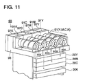
- Fig. 11 is a perspective view of the toner replenishing device 90 mounted with the toner container 80Y, 80M, 80C, and 80K.
- Each of the container mounting portions 91Y, 91M, 91C, and 91K has each of the four toner containers 80Y, 80M, 80C, and 80K respectively placed parallelly on about the same plane and enables them to be mounted or dismounted.
- Each of the toner storing portions 97Y, 97M, 97C, and 97K stores each color toner respectively, and upon decreasing of the amount of any toner in said developing units 20Y, 20M, 20C, and 20K, the corresponding toner is replenished in a controlled manner.
- toner containers 80Y, 80M, 80C, and 80K all have almost the same constrution, hereinafter the explanation will be given with reference to the container 80 as the representative of the containers 80Y, 80M, 80C, and 80K; the container mounting portion 91 is refered to as the representative of container mounting portions 91Y, 91M, 91C, and 91K; and the toner storing portion 97 is refered to as the representative of the toner storing portions 97Y, 97M, 97C, and 97K.
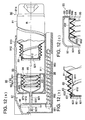
- Fig. 12 (a) shows a cross-sectional view of the aforesaid container mounting portion 91 of the toner replenishing device 90 and the toner container 80 before mounted, that is, as they are spaced apart;
- Fig. 12 (b) is an enlarged partial cross-sectional view of said container 80;
- Fig. 12 (c) is an enlarged partial cross-sectional view of the container mounting portion 91.
- the container 80 is composed of a cylindrical container body 81 containing the toner inside, a fixed cover 82 to fix the side surface, in the direction of the rotation axis, of said container body 81, and a container opening-or-closing cover 83 which is fixed at its one end to the aforesaid container body and capable of expansion and contraction.
- An opening is provided on the projected portion of one side, with regard to the direction of the rotation axis, and is closed and fixed by the aforesaid fixed cover 82.
- a guide portion (toner conducting portion) consisting of a coil-shaped protrusion 811 is formed on the inner surface of said container body 81, and the toner contained in the container body 81 is guided along the coil-shaped protrusion 811 to move to the direction of the fixed cover 82.
- a plurality of openings (toner discharging openings) 812 for discharging the toner in the container body 81 is porvided through its wall, the toner conveyed through the container mounting portion 91 of the toner replenishing device, which will be explained later, to be received and accumulated in the toner storing portion 97.
- a flat bumping portion 821 is formed, and contacts the opening-or-closing cover 94 (for the mounting portion) of the container mounting portion 91. Further, a ring-shaped projected portion is formed on the peripheral surface of the aforesaid fixed cover 82 unitedly, engages, being capable of engaging and disengaging, with the engaging portion (free end) 831 provided in the vicinity of the left end, with regard to the drawing, of the aforesaid container opening-or-closing cover, which is capable of expansion and contraction.
- the open surface at the right-hand side, with regard to the drawing, of the aforesaid container opening-or-closing cover 83 is a fixing portion (fixed end) 832 which is fixed with close contact to the peripheral surface of the aforesaid container body 81.
- Said fixing portion 832 is bonded or welded to the container body to make both united.
- the aforesaid container-opening-or-closing cover 83 is made of polyethylene resin, is formed by blow molding method, having flexibility, with its outer surface formed to have a pluralty of folds like a bellow, and is capable of expansion and contraction in the direction of the rotation axis R.
- the inside of the container opening-or-closing cover 83 forms a through hollow space.
- the aforesaid container mounting portion 91 is composed of an outer cylinder member 92, an inner cylinder member 93, the mounting-portion opening-or-closing cover 94 capable of expansion and contraction, a coil spring 95, and the container rotating gear 96.
- Said outer cylinder member 92 and said inner cylinder member 93 are formed unitedly, and making up the toner guiding means which receives the toner discharged out of the container 80, and conveys it to replenish the aforesaid toner storing portion 97 with it.
- the rotary shaft portion 921 to the left-hand side, with regard to the drawing, of the aforesaid outer cylinder member 92 is supported, being capable of rotation, by the two parallel upright walls which makes up the aforesaid toner storing portion (toner hopper) 97.
- the container rotating gear 96 is fixed. Said container rotating gear 96 is driven to rotate by a drive source which is not shown in the drawings.
- the central portion of the aforesaid rotary shaft portion 921 is hollow, with a through hole 922 formed therein. Said through hole 922 is made in order that when the container 80 is mounted to the container mounting portion 91, the air in the mounting-portion opening-or-closing cover 94, compressed by the bumping portion 821 at the end of the container 80, may exhaust through the exhausting hole 923 to the outside of the toner replenishing device 90.
- a plurality of openings (toner discharging openings) 931 is provide through its wall.
- Said opening 931 communicates with the toner conveying path 924 formed by the aforesaid outer cylinder member 92 and inner cylinder member 93, and further with the aforesaid toner storing portion 97 through the toner replenishing opening 925 provided at the side of the outer cylinder member through its wall.
- the engaging protrusion 932 projecting inward at the entrance portion on one side of the aforesaid inner cylinder member 93 engages with the end portion (free end) 942 at the entrance of the aforesaid mounting-portion opening-or-closing cover 94 to prevent the slipping off. Further, the engaging wall portion 933 at the other side of the inner cylinder member 93 is fixed (fused) with the engaging portion (fixed end) 943 at the innermost side of the mounting-portion opening-or-closing cover 94 by ultrasonic bonding. This bonding may be substituted by fixing with an adhesive.
- the aforesaid mounting-portion opening-or-closing cover 94 is made of the polyethylene resin and is formed by blow molding method, having flexibility, with its outer surface formed to have a plurality of folds like a bellow, and is capable of expansion and contraction in the direction of the rotation axis R.
- the inside of the mounting-portion opening-or-closing cover 94 forms a through hollow space.
- the aforesaid coil spring 95 is placed in said space, being capable of expansion and contraction. Said coil spring 95 extends the mounting-portion opening-or-closing cover 94 by pressing it from the inside.
- the end portion at the entrance side of the mounting-portion opening-or-closing cover 94 is urged with the aforesaid coil spring 95, but it is a free end, being movable by an external force in the direction of rotation axis R.
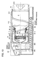
- Fig. 13 is a cross-sectional view of the toner replenishing device with the toner container 80 mounted to the container mounting portion 91, that is, a cross-sectional view showing the container 80, the container mounting portion 91, toner storing portion 97, and the toner feeding portion 98;
- Fig. 14 is an enlarged partial cross-sectional view of the toner container 80 and the container mounting portion 91; and
- Fig. 15 is a cross-sectional view through A-A of the toner container 80 and the container mounting portion 91 shown in Fig. 13.
- the aforesaid container 80 is held and placed on the guiding platform 911 of the container mounting portion 91 to be moved to the left direction, with regard to the drawing; the bumping portion of the extreme end of the container 80 is made contact the right side of the aforesaid mounting-portion opening-or-closing cover 94.
- the convex portion of the container opening-or-closing cover 83 bumps the entrance wall 934 of the aforesaid inner cylinder member 93, prevented from going forward; while the bellow portion of the container opening-or-closing cover 83 is compressed, the engaging portion 831 of the container opening-or-closing cover 83 disengages with the bumping portion 821 to be spaced apart; further, the fixed cover 82 presses the mounting-portion opening-or-closing cover 94.
- the mounting-portion opening-or-closing cover 94 is compressed against the coil spring 95, thus the aforesaid opening (toner discharging opening) 931 is gradually opened to reach to the full-open state.
- This opening 931 in the full-open state comes to the same position as that of one of the openings 812 of the aforesaid container body 81, and that enables the discharging of the toner in the container body 81 to the opening 931 through the openings 812.
- the openings 812 are provided at four positions of the container body 81 through its wall, and protrusions 813 are provided at two positions on its periphery. Said protrusions 813 are fitted to some of the concaves 935 provided at four positions on the inner wall of the inner cylinder member 93.
- each of paddles 936 which sum to four in all, is protruded.
- Said paddles 936 are skewed to the direction of the rotation axis R, and cause the toner conveyed through the toner feeding path 924 to be discharged smoothly.
- Said paddles (scooping-up portion) 936 scoop up the toner ejected from said openings 931 and convey it in the toner feeding path 924, and then discharge it through the toner replenishing opening 925.
- the toner discharged from the toner replenishing opening 925 passes through the opening 973 in the upright wall 971 of the toner storing portion 97, and is received in the hopper.
- the amount of the toner received in said toner storing portion 97 is detected by a photo-detector means, which is not shown in the drawing, and when the amount of the replenished toner reaches to a predetermined value, the driving of drive source is stopped to cease the replenishing of the toner from the toner storing portion 97.
- the toner received in the hopper of the toner storing portion 97 is fed into the feeding screw 982 fixed to the feeding-screw gear 981 linked to the drive source, not shown in the drawing, conveyed through the toner feeding portion, and replenished to the aforesaid developing unit 20.
- a cover member 912 is arranged fixedly.
- an elastic member 913 for preventing slipping off of the container mounted is fixed and engages with the step portion 814 of the container body 81.
- said elastic member 913 for preventing slipping off may be formed unitedly with a portion of the cover member 912.
- said elastic member 913 for preventing slipping off usable also as the member for preventing wrong mounting when the plural number of containers 80Y, 80M, 80C, and 80K are mounted to the prescribed container mounting portion 91Y, 91M, 91C, and 91K.
Landscapes
- Physics & Mathematics (AREA)
- General Physics & Mathematics (AREA)
- Dry Development In Electrophotography (AREA)
Claims (9)
- Réservoir de toner (30K; 30C; 30M; 30Y) utilisé dans un dispositif de production d'images pourvu d'une section de réception du toner (41) comprenant:caractérisé en ce queun corps de réservoir cylindrique (31) dans lequel le toner est livré, et dans lequel ledit corps de réservoir cylindrique (31) est pourvu d'une extrémité de décharge (312) et est pourvu d'une nervure spirale (311) disposée sur sa face circonférencielle intérieure de telle sorte que le toner peut être transporté à l'aide de la nervure spirale vers l'extrémité de décharge lorsque le corps de réservoir cylindrique est mis en rotation, et dans lequel le corps de réservoir cylindrique comprend en outre une section cylindrique (324) pourvue d'une ouverture de sortie (324) disposée à l'extrémité de sortie du toner; etun manchon (33) disposé autour de la section cylindrique (32) de telle sorte que ladite ouverture de sortie du toner peut être fermée à l'aide de ce manchon, et dans lequel ce manchon peut être déplaçé dans la direction axiale de la section cylindrique de telle sorte que lorsque le réservoir de toner est fixé à la section de réception (41) du dispositif de formation d'images ce manchon est déplaçé pour ouvrir ladite ouverture de sortie du toner (324),
le manchon (33) est capable d'expansion et de contraction. - Dispositif suivant la revendication 1,
caractérisé en ce que
le manchon (33) est un élément rétractil permettant le retour du manchon pour fermer l'ouverture de sortie du toner (324) lorsque le réservoir de toner (30) est détaché de le section de réception (41) du dispositif de formation d'images. - Dispositif suivant la revendication 2,
caractérisé en ce que
le manchon (33) a la forme d'un soufflet. - Dispositif suivant la revendication 1,
caractérisé en ce que
ce dispositif comprend en outre:un élément de louche (325) pour écoper une quantité de toner au-dessus de l'axe de rotation (R) du corps de réservoir cylindrique (30) lorsque le corps de réservoir cylindrique est mis en rotation; ainsi qu'un élément de guidage (326) transportant le toner écopé vers l'ouverture de sortie (324). - Dispositif suivant la revendication 1,
caractérisé en ce que
la section cylindrique (32) est pourvue sur sa circonférence intérieure d'une nervure spirale et d'une section de réception à travers de laquelle le toner écopé est introduit goutte-à- goutte dans ladite section cylindrique, et dans lequel le faner est transporté à l'aide de la nervure spirale de l'ouverture de réception à l'ouverture de sortie lorsque la section cylindrique est mise en rotation avec le corps de réservoir cylindrique. - Dispositif pour la fourniture d'un toner à un appareil de formation d'images incluant
un réservoir (30) comprenant
un corps de réservoir cylindrique (31) dans lequel le toner est livré, et dans lequel le corps du réservoir cylindrique est pourvu d'une ouverture de sortie (312) et étant également pourvue d'une nervure spirale (311) disposée sur sa circonférence intérieure de telle sorte que le toner peut être transporté à l'aide de cette nervure spirale vers l'ouverture de sortie lorsque le corps de réservoir cylindrique est mis en rotation, et dans lequel le corps de réservoir cylindrique comprend en outre une section cylindrique (32) pourvue d'une ouverture de sortie (324) prévue du coté de l'extrémité de sortie,
caractérisé en ce que
il comprend un manchon (33) capable d'expansion et de contraction qui est monté sur la section cylindrique (32) de telle manière que l'ouverture de sortie peut être fermée à l'aide de ce manchon; et
une section de réception (41) du toner pourvue d'une encoche (44) équipée d'une ouverture de sortie du toner (441), et que ledit manchon est déplaçable dans la direction axiale (R) de la section cylindrique de telle sorte que lorsque la section cylindrique (32) est placée dans l'encoche (44) ce manchon (33) est déplacé de telle sorte qu'il ouvre l'ouverture de sortie (324) et le toner est fourni à travers de ladite ouverture de sortie du réservoir de toner et l'ouverture de réception du toner à la section (441) de réception. - Dispositif suivant la revendication 6,
caractérisé en ce que
l'encoche (44) présente la forme d'une encoche cylindrique. - Dispositif suivant la revendication 7,
caractérisé en ce que
ladite encoche cylindrique (44) est rotative, et que sur la face circonférentielle extérieure de cette encoche cylindrique est disposé un élément de louche pour prélever une quantité de toner au-dessus de l'axe de rotation de cette encoche cylindrique, lorsque cette encoche cylindrique est tournée avec le corps de réservoir cylindrique et en ce que la quantité de toner prélevée est guidée sur la face circonférentielle extérieure de l'encoche cylindrique. - Dispositif suivant la revendication 6,
caractérisé en ce que
le manchon (33) consiste d'un soufflet, et en ce que ce soufflet est retiré de sorte à ouvrir l'ouverture de sortie (324) lorsque cette section cylindrique est insérée dans ladite encoche.
Applications Claiming Priority (6)
| Application Number | Priority Date | Filing Date | Title |
|---|---|---|---|
| JP459997 | 1997-01-14 | ||
| JP460097 | 1997-01-14 | ||
| JP460097 | 1997-01-14 | ||
| JP459997 | 1997-01-14 | ||
| JP4599/97 | 1997-01-14 | ||
| JP4600/97 | 1997-01-14 |
Publications (3)
| Publication Number | Publication Date |
|---|---|
| EP0853260A2 EP0853260A2 (fr) | 1998-07-15 |
| EP0853260A3 EP0853260A3 (fr) | 2000-01-12 |
| EP0853260B1 true EP0853260B1 (fr) | 2003-11-05 |
Family
ID=26338406
Family Applications (1)
| Application Number | Title | Priority Date | Filing Date |
|---|---|---|---|
| EP98100445A Expired - Lifetime EP0853260B1 (fr) | 1997-01-14 | 1998-01-13 | Cartouche de dévelppateur et appareil de remplissage de développateur |
Country Status (3)
| Country | Link |
|---|---|
| US (1) | US5890040A (fr) |
| EP (1) | EP0853260B1 (fr) |
| DE (1) | DE69819373T2 (fr) |
Families Citing this family (50)
| Publication number | Priority date | Publication date | Assignee | Title |
|---|---|---|---|---|
| US5970293A (en) * | 1999-01-29 | 1999-10-19 | General Plastic Industrial Co., Ltd. | Developer container for use with a developer replenishing device |
| US6169864B1 (en) * | 1999-07-06 | 2001-01-02 | Xerox Corporation | Toner container including a movably mounted sealing member |
| US6137972A (en) * | 1999-08-30 | 2000-10-24 | Xerox Corporation | Imaging material dispensing system |
| US6334037B1 (en) | 2000-02-18 | 2001-12-25 | Toshiba Tec Kabushiki Kaisha | Image forming apparatus |
| US6256470B1 (en) * | 2000-02-18 | 2001-07-03 | Toshiba Tec Kabushiki Kaisha | Toner supply device for use in image forming system and toner cartridge for use therein |
| US6289182B1 (en) | 2000-02-18 | 2001-09-11 | Toshiba Tec Kabushiki Kaisha | Method and apparatus for discriminating toner bottle types, stirring toner, and detecting the amount of remaining toner |
| EP1233311B1 (fr) * | 2001-02-19 | 2012-08-29 | Canon Kabushiki Kaisha | Récipient d'alimentation en toner |
| US6990301B2 (en) * | 2001-02-19 | 2006-01-24 | Canon Kabushiki Kaisha | Sealing member, toner accommodating container and image forming apparatus |
| ES2433741T3 (es) * | 2001-02-19 | 2013-12-12 | Canon Kabushiki Kaisha | Contenedor para suministro de tóner y sistema de suministro de tóner |
| US6922540B2 (en) * | 2001-10-03 | 2005-07-26 | Canon Kabushiki Kaisha | Developer supply kit |
| JP4124992B2 (ja) * | 2001-10-25 | 2008-07-23 | キヤノン株式会社 | トナー補給容器 |
| JP4095875B2 (ja) * | 2001-10-30 | 2008-06-04 | 株式会社リコー | 現像剤収納容器及び画像形成装置 |
| US6987942B2 (en) * | 2002-04-24 | 2006-01-17 | Canon Kabushiki Kaisha | Toner supply kit |
| DE60312426T2 (de) * | 2002-04-24 | 2007-11-29 | Canon K.K. | Entwicklerzufuhrbehälter |
| US7542703B2 (en) * | 2002-05-20 | 2009-06-02 | Ricoh Company, Ltd. | Developing device replenishing a toner or a carrier of a two-ingredient type developer and image forming apparatus including the developing device |
| JP3997112B2 (ja) * | 2002-05-24 | 2007-10-24 | キヤノン株式会社 | 現像剤補給装置 |
| EP1542088B1 (fr) * | 2002-09-20 | 2016-12-14 | Ricoh Company, Ltd. | Contenant de stockage de toner |
| JP2004139031A (ja) * | 2002-09-24 | 2004-05-13 | Ricoh Co Ltd | 画像形成装置、補給用トナー収容器およびプロセスカートリッジ |
| JP4352848B2 (ja) * | 2003-02-14 | 2009-10-28 | 富士ゼロックス株式会社 | 現像剤カートリッジ、画像形成装置および現像剤カートリッジのリサイクル方法 |
| JP4383898B2 (ja) * | 2003-02-28 | 2009-12-16 | 株式会社リコー | 現像剤収容器、現像剤供給装置及び画像形成装置 |
| JP4205531B2 (ja) * | 2003-08-25 | 2009-01-07 | 株式会社リコー | 搬送装置及び画像形成装置 |
| JP2005082152A (ja) * | 2003-09-04 | 2005-03-31 | Ricoh Co Ltd | 容器及びトナー補給装置 |
| JP2005221825A (ja) * | 2004-02-06 | 2005-08-18 | Ricoh Co Ltd | トナーボトル及びその製造方法、トナー容器、トナーカートリッジ並びに、画像形成装置 |
| JP4656561B2 (ja) * | 2004-03-05 | 2011-03-23 | 株式会社リコー | トナー容器、トナー補給装置、現像装置、プロセスカートリッジ、及び、画像形成装置 |
| JP4456957B2 (ja) * | 2004-08-06 | 2010-04-28 | 株式会社リコー | トナーカートリッジ及び画像形成装置 |
| US7720416B2 (en) * | 2004-08-16 | 2010-05-18 | Ricoh Company, Ltd. | Method and toner bottle for image forming apparatus capable of effectively supplying toner to image forming apparatus |
| MXPA06012659A (es) * | 2005-04-27 | 2007-01-16 | Ricoh Kk | Recipiente de toner y aparato formador de imagen. |
| WO2006132259A1 (fr) * | 2005-06-07 | 2006-12-14 | Ricoh Company, Limited | Conteneur de toner et dispositif de formation d’image |
| JP4376851B2 (ja) * | 2005-10-07 | 2009-12-02 | シャープ株式会社 | 現像剤補給装置 |
| JP4376852B2 (ja) * | 2005-10-07 | 2009-12-02 | シャープ株式会社 | 現像剤補給装置 |
| JP4376853B2 (ja) * | 2005-10-07 | 2009-12-02 | シャープ株式会社 | 現像剤補給装置 |
| US7729644B2 (en) * | 2006-05-11 | 2010-06-01 | Katun Corporation | Toner cartridge |
| KR100873449B1 (ko) * | 2006-07-20 | 2008-12-11 | 삼성전자주식회사 | 토너탱크, 슬라이드 셔터, 실링부재, 탄성부재, 및 이를 구비한 토너공급장치 |
| US8050597B2 (en) * | 2006-11-09 | 2011-11-01 | Ricoh Company, Limited | Toner container having a gear portion and image forming apparatus |
| JP5003788B2 (ja) * | 2010-04-26 | 2012-08-15 | 富士ゼロックス株式会社 | 現像剤搬送部材及びこれを用いた現像剤収容容器、画像形成装置 |
| BR112013013698B1 (pt) | 2010-12-03 | 2020-12-29 | Ricoh Company, Ltd | recipiente de pó, dispositivo de alimentação de pó e aparelho de formação de imagem |
| JP5640935B2 (ja) * | 2011-09-14 | 2014-12-17 | コニカミノルタ株式会社 | トナー補給機構 |
| KR102367636B1 (ko) | 2011-11-25 | 2022-02-28 | 가부시키가이샤 리코 | 분체 수납 용기 및 화상 형성 장치 |
| AU2016277648B2 (en) * | 2011-11-25 | 2019-02-07 | Ricoh Company, Limited | Powder Container And Image Forming Apparatus |
| KR102002623B1 (ko) | 2012-06-03 | 2019-07-22 | 가부시키가이샤 리코 | 분체 용기 및 화상 형성 장치 |
| US9465317B2 (en) | 2013-02-25 | 2016-10-11 | Ricoh Company, Ltd. | Nozzle insertion member, powder container, and image forming apparatus |
| ES2873974T3 (es) | 2013-03-15 | 2021-11-04 | Ricoh Co Ltd | Depósito de polvo y aparato de formación de imágenes |
| JP6025631B2 (ja) | 2013-03-22 | 2016-11-16 | キヤノン株式会社 | 現像剤補給容器 |
| US20160091827A1 (en) * | 2014-09-25 | 2016-03-31 | Fuji Xerox Co., Ltd. | Powder storage device and image-forming apparatus |
| JP6665431B2 (ja) * | 2015-06-24 | 2020-03-13 | 株式会社リコー | 粉体収容容器及び画像形成装置 |
| CN107479354B (zh) * | 2017-09-05 | 2020-11-03 | 上福全球科技股份有限公司 | 墨粉盒 |
| CN107422618A (zh) * | 2017-09-26 | 2017-12-01 | 天津市志捷科技股份有限公司 | 打印机硒鼓加粉防尘罩 |
| BR112020004447A2 (pt) | 2017-10-05 | 2020-09-15 | Hewlett-Packard Development Company, L.P. | recipiente de material de construção para uma impressora tridimensional |
| US11249420B2 (en) * | 2019-10-07 | 2022-02-15 | Katun Corporation | Toner cartridge interface mechanism and methods for same |
| US11768449B2 (en) * | 2021-04-19 | 2023-09-26 | Kyocera Document Solutions Inc. | Developer storage container capable of reducing remaining developer at time of replacement, image forming apparatus |
Family Cites Families (9)
| Publication number | Priority date | Publication date | Assignee | Title |
|---|---|---|---|---|
| US4307763A (en) * | 1979-11-29 | 1981-12-29 | International Business Machines Corporation | Toner container |
| US4937625A (en) * | 1987-08-28 | 1990-06-26 | Sharp Kabushiki Kaisha | Developing device for copier |
| JPH04372967A (ja) * | 1991-06-21 | 1992-12-25 | Toshiba Corp | 画像形成装置 |
| TW240299B (fr) * | 1992-12-30 | 1995-02-11 | Ricoh Kk | |
| US5398849A (en) * | 1993-06-28 | 1995-03-21 | Nu-Kote International | Cartridge with slide mechanism for dispensing toner |
| JP3245288B2 (ja) * | 1993-12-24 | 2002-01-07 | 株式会社リコー | トナー収納容器 |
| US5589919A (en) * | 1994-04-26 | 1996-12-31 | Konica Corporation | Toner cartridge and color image forming apparatus in use therewith |
| US5546984A (en) * | 1994-06-14 | 1996-08-20 | Hewlett-Packard Company | Bellows-type, low spillage, quick disconnect unit |
| JP3875743B2 (ja) * | 1996-01-09 | 2007-01-31 | 株式会社リコー | 現像装置及びトナーボトル |
-
1998
- 1998-01-12 US US09/020,302 patent/US5890040A/en not_active Expired - Lifetime
- 1998-01-13 EP EP98100445A patent/EP0853260B1/fr not_active Expired - Lifetime
- 1998-01-13 DE DE69819373T patent/DE69819373T2/de not_active Expired - Lifetime
Also Published As
| Publication number | Publication date |
|---|---|
| EP0853260A3 (fr) | 2000-01-12 |
| DE69819373T2 (de) | 2004-05-06 |
| EP0853260A2 (fr) | 1998-07-15 |
| DE69819373D1 (de) | 2003-12-11 |
| US5890040A (en) | 1999-03-30 |
Similar Documents
| Publication | Publication Date | Title |
|---|---|---|
| EP0853260B1 (fr) | Cartouche de dévelppateur et appareil de remplissage de développateur | |
| JP3861428B2 (ja) | トナー収納容器及びトナー補給装置 | |
| US7486916B2 (en) | Method and apparatus of image forming and process cartridge included in the apparatus | |
| KR100747728B1 (ko) | 현상제 용기, 현상제 공급 장치 및 화상 형성 장치 | |
| US5576816A (en) | Toner cartridge internal plug | |
| JP3541691B2 (ja) | 画像形成装置及び現像剤収納容器 | |
| EP1184741B1 (fr) | Unité avec une ouverture d'alimentation en développateur et appareil de formation d'images l'utilisant | |
| EP1403733A1 (fr) | Appareil de formation d'images avec un récipient de toner réapprovisionant une cartouche de traitement | |
| US7106995B2 (en) | Developer cartridge container, developer cartridge, image forming unit, recycling method of developer cartridge container, and recycling method of developer cartridge | |
| JP3572500B2 (ja) | 現像剤補給装置及び現像剤カートリッジ | |
| US5903806A (en) | Developing agent replenishing apparatus and cartridge | |
| EP0639801A1 (fr) | Appareil de formation d'images en couleurs muni d'une unité de procédé et d'une cartouche de matériau de développement en couleurs | |
| JP3861429B2 (ja) | トナー補給装置 | |
| JPH09211947A (ja) | 現像剤収納容器及び現像剤供給装置 | |
| CA2174872C (fr) | Garniture de cartouche d'alimentation en toner | |
| JPH04366877A (ja) | 画像形成装置 | |
| US7349646B2 (en) | Toner cartridge used with an electrophotographic image forming apparatus | |
| JP4039231B2 (ja) | 画像形成装置 | |
| JPH0484170A (ja) | 画像形成装置 | |
| KR100601675B1 (ko) | 전자사진방식 화상형성장치 | |
| JP2004198768A (ja) | 廃棄粉体回収装置、画像形成装置 | |
| JPH1063076A (ja) | 現像剤カートリッジ及び現像剤補給装置 | |
| JPH02300769A (ja) | カラー画像形成装置 | |
| JPH07295356A (ja) | トナーカートリッジ | |
| JPH0495980A (ja) | 画像形成装置 |
Legal Events
| Date | Code | Title | Description |
|---|---|---|---|
| PUAI | Public reference made under article 153(3) epc to a published international application that has entered the european phase |
Free format text: ORIGINAL CODE: 0009012 |
|
| AK | Designated contracting states |
Kind code of ref document: A2 Designated state(s): DE FR GB |
|
| AX | Request for extension of the european patent |
Free format text: AL;LT;LV;MK;RO;SI |
|
| PUAL | Search report despatched |
Free format text: ORIGINAL CODE: 0009013 |
|
| AK | Designated contracting states |
Kind code of ref document: A3 Designated state(s): AT BE CH DE DK ES FI FR GB GR IE IT LI LU MC NL PT SE |
|
| AX | Request for extension of the european patent |
Free format text: AL;LT;LV;MK;RO;SI |
|
| 17P | Request for examination filed |
Effective date: 20000628 |
|
| AKX | Designation fees paid |
Free format text: DE FR GB |
|
| 17Q | First examination report despatched |
Effective date: 20020715 |
|
| GRAH | Despatch of communication of intention to grant a patent |
Free format text: ORIGINAL CODE: EPIDOS IGRA |
|
| GRAS | Grant fee paid |
Free format text: ORIGINAL CODE: EPIDOSNIGR3 |
|
| GRAA | (expected) grant |
Free format text: ORIGINAL CODE: 0009210 |
|
| AK | Designated contracting states |
Kind code of ref document: B1 Designated state(s): DE FR GB |
|
| REG | Reference to a national code |
Ref country code: GB Ref legal event code: FG4D |
|
| REF | Corresponds to: |
Ref document number: 69819373 Country of ref document: DE Date of ref document: 20031211 Kind code of ref document: P |
|
| PGFP | Annual fee paid to national office [announced via postgrant information from national office to epo] |
Ref country code: GB Payment date: 20040107 Year of fee payment: 7 |
|
| PGFP | Annual fee paid to national office [announced via postgrant information from national office to epo] |
Ref country code: FR Payment date: 20040108 Year of fee payment: 7 |
|
| ET | Fr: translation filed | ||
| PLBE | No opposition filed within time limit |
Free format text: ORIGINAL CODE: 0009261 |
|
| STAA | Information on the status of an ep patent application or granted ep patent |
Free format text: STATUS: NO OPPOSITION FILED WITHIN TIME LIMIT |
|
| 26N | No opposition filed |
Effective date: 20040806 |
|
| PG25 | Lapsed in a contracting state [announced via postgrant information from national office to epo] |
Ref country code: GB Free format text: LAPSE BECAUSE OF NON-PAYMENT OF DUE FEES Effective date: 20050113 |
|
| GBPC | Gb: european patent ceased through non-payment of renewal fee |
Effective date: 20050113 |
|
| PG25 | Lapsed in a contracting state [announced via postgrant information from national office to epo] |
Ref country code: FR Free format text: LAPSE BECAUSE OF NON-PAYMENT OF DUE FEES Effective date: 20050930 |
|
| REG | Reference to a national code |
Ref country code: FR Ref legal event code: ST |
|
| PGFP | Annual fee paid to national office [announced via postgrant information from national office to epo] |
Ref country code: DE Payment date: 20160105 Year of fee payment: 19 |
|
| REG | Reference to a national code |
Ref country code: DE Ref legal event code: R119 Ref document number: 69819373 Country of ref document: DE |
|
| PG25 | Lapsed in a contracting state [announced via postgrant information from national office to epo] |
Ref country code: DE Free format text: LAPSE BECAUSE OF NON-PAYMENT OF DUE FEES Effective date: 20170801 |