EP0853263A2 - Anschluss für Uhrenarmband - Google Patents
Anschluss für Uhrenarmband Download PDFInfo
- Publication number
- EP0853263A2 EP0853263A2 EP97308354A EP97308354A EP0853263A2 EP 0853263 A2 EP0853263 A2 EP 0853263A2 EP 97308354 A EP97308354 A EP 97308354A EP 97308354 A EP97308354 A EP 97308354A EP 0853263 A2 EP0853263 A2 EP 0853263A2
- Authority
- EP
- European Patent Office
- Prior art keywords
- component
- connector
- lugs
- bottom component
- watch case
- Prior art date
- Legal status (The legal status is an assumption and is not a legal conclusion. Google has not performed a legal analysis and makes no representation as to the accuracy of the status listed.)
- Withdrawn
Links
Images


Classifications
-
- A—HUMAN NECESSITIES
- A44—HABERDASHERY; JEWELLERY
- A44C—PERSONAL ADORNMENTS, e.g. JEWELLERY; COINS
- A44C5/00—Bracelets; Wrist-watch straps; Fastenings for bracelets or wrist-watch straps
- A44C5/14—Bracelets; Wrist-watch straps; Fastenings for bracelets or wrist-watch straps characterised by the way of fastening to a wrist-watch or the like
-
- Y—GENERAL TAGGING OF NEW TECHNOLOGICAL DEVELOPMENTS; GENERAL TAGGING OF CROSS-SECTIONAL TECHNOLOGIES SPANNING OVER SEVERAL SECTIONS OF THE IPC; TECHNICAL SUBJECTS COVERED BY FORMER USPC CROSS-REFERENCE ART COLLECTIONS [XRACs] AND DIGESTS
- Y10—TECHNICAL SUBJECTS COVERED BY FORMER USPC
- Y10T—TECHNICAL SUBJECTS COVERED BY FORMER US CLASSIFICATION
- Y10T24/00—Buckles, buttons, clasps, etc.
- Y10T24/47—Strap-end-attaching devices
- Y10T24/4718—Watch pintle connected
-
- Y—GENERAL TAGGING OF NEW TECHNOLOGICAL DEVELOPMENTS; GENERAL TAGGING OF CROSS-SECTIONAL TECHNOLOGIES SPANNING OVER SEVERAL SECTIONS OF THE IPC; TECHNICAL SUBJECTS COVERED BY FORMER USPC CROSS-REFERENCE ART COLLECTIONS [XRACs] AND DIGESTS
- Y10—TECHNICAL SUBJECTS COVERED BY FORMER USPC
- Y10T—TECHNICAL SUBJECTS COVERED BY FORMER US CLASSIFICATION
- Y10T24/00—Buckles, buttons, clasps, etc.
- Y10T24/47—Strap-end-attaching devices
- Y10T24/4782—Watch strap
Definitions
- This invention relates to an improved end connector assembly for coupling the ends of an expansible watchband to a watch case molded from a plastic material, such as for example ABS.
- end connectors comprising an assembly of top and bottom metal components having a plastic insert interposed therebetween.
- the watch case and the plastic insert each have spaced lugs which are interengaged in a tongue-and-groove type joint.
- a metal pin is inserted through aligned apertures in the interengaged lugs to connect the end connector to the watch case.
- the primary function of the plastic insert is to exert an elastic clamping force on the pin, thereby opposing any tendency of the pin to work its way free.
- the present inventors have sought primarily to obviate the aforesaid problem by eliminating the plastic insert from the end connector assembly.
- an end connector assembly comprising metal bottom and top components configured and dimensioned to be joined together with only a terminal top link of the watchband securely captured therebetween.
- the bottom component includes hollow guides which can be aligned axially with apertured lugs on the watch case to receive the metal connecting pin.
- the bottom component preferably further includes a spring member in resilient contact with the connecting pin.
- the hollow guides have reduced diameter portions serving to contact and guide the connecting pin, and enlarged diameter portions around which flanges of the top component are bent during assembly of the top component onto the bottom component.
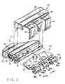
- an expansible watchband 10 is shown coupled to a plastic watch case 12 by means of an end connector assembly 14 in accordance with the present invention.
- the end connector assembly at the opposite end of the band is shown uncoupled from the watch case as a result of the extraction of a metallic cross pin 16.
- the watchband 10 is of the conventional type, having rows of top links 18 connected to rows of bottom links 20 by U-shaped staples and internal springs (not shown) in a manner well known to those skilled in the art. With the exception of the terminal top link 18, all of the other top links are covered by decorative metallic top shells 22.
- the watch case 12 has lugs 25 separated by sockets 26. Aligned apertures 28 extend through the lugs 24 in a direction transverse to the length of the watchband.
- the end connector 14 is comprised of a bottom component 30 and a top component 32.
- Bottom component 30 has a planar rear end 34 with an upwardly projecting tooth 36, and a front end with mutually spaced projections 38, 40.
- At least the two projections 38 on either side of the center projection 40 define hollow substantially cylindrical guides.
- the projections 38 have reduced diameter central wall portions 38a located between and joined to enlarged diameter end wall portions 38b by intermediate conical sections 38c.
- the central projection 40 is only partially cylindrical and is configured to be resiliently deflectable.
- Projection 40 also has a reduced diameter central wall portion 40a located between and joined to enlarged diameter end wall portions 40b by intermediate conical sections 40c.
- the wall portions 38a and 38b of projections 38 have a common central axis A 1 .
- the wall portions 40a and 40b of central projection 40 have a common axis A 2 , with axis A 2 being offset from axis A 1 .
- the top component 32 has a front end with mutually spaced flanges 42, 44 and a box-shape rear end defined by a top wall 46, side walls 48 with depending tabs 50, and a rear wall 52.
- the top wall 46 is configured and dimensioned to provide a continuation of the decorative appearance provided by the top shells 22 applied to the top links 18.
- the planar rear end 34 of the bottom component 30 is first inserted beneath the terminal top link 18.
- the tooth 36 of the bottom component is engaged in a notch 60 on the underside of the terminal top link.
- the top component 32 is then assembled onto the bottom component 30.
- the flanges 42, 44 are bent respectively around the projections 38, 40 to thereby form second lugs 54 separated by second sockets 56 (see Figures 1 and 4).
- the rear wall 52 of the top component is engaged behind the terminal top link 18, the latter being firmly captured between the top wall 46 of the top component and the planar rear end 34 of the bottom component.
- the tabs 50 are bent under the planar rear end 34 to complete the assembly.
- the end connector 14 is attached to the watch case 12 in the following manner: the second lugs 54 of the end connector are located in the sockets 26 of the watch case, with the lugs 24 of the watch case being located in the sockets 56 of the end connector.
- the metallic pin 16 then inserted through the apertures 28 of the watch case lugs 24 and the tubular guides provided by the projections 38 of the bottom component 30.
- the pin 16 has a reduced diameter middle section 58. As the pin progresses through the assembly, the center projection 40 on the bottom component is momentarily deflected, placing its axis A 2 in alignment with the axis A 1 of the projections 38.
- the end connector of the present invention can be subjected along with the watchband to PVD coating without suffering the deleterious effects of plastic components.
- the resulting reduction in the number of components making up the connector reduces overall costs and simplifies assembly procedures. All this is achieved while still providing a reliable means for retaining the connecting pin in its inserted position following assembly of the watchband onto the plastic watch case.
- end connector of the present invention is not restricted in use to expansible watchbands.
- non-expansible watchbands having links interconnected by pins or the like could be joined to a watch case with the same end connector assembly.
Landscapes
- Connector Housings Or Holding Contact Members (AREA)
- Coupling Device And Connection With Printed Circuit (AREA)
- Connection Of Plates (AREA)
Applications Claiming Priority (2)
| Application Number | Priority Date | Filing Date | Title |
|---|---|---|---|
| US08/758,726 US5724708A (en) | 1996-12-03 | 1996-12-03 | End connector assembly for watchband |
| US758726 | 2001-01-11 |
Publications (2)
| Publication Number | Publication Date |
|---|---|
| EP0853263A2 true EP0853263A2 (de) | 1998-07-15 |
| EP0853263A3 EP0853263A3 (de) | 2000-12-27 |
Family
ID=25052848
Family Applications (1)
| Application Number | Title | Priority Date | Filing Date |
|---|---|---|---|
| EP97308354A Withdrawn EP0853263A3 (de) | 1996-12-03 | 1997-10-21 | Anschluss für Uhrenarmband |
Country Status (3)
| Country | Link |
|---|---|
| US (1) | US5724708A (de) |
| EP (1) | EP0853263A3 (de) |
| CN (1) | CN1183934A (de) |
Families Citing this family (12)
| Publication number | Priority date | Publication date | Assignee | Title |
|---|---|---|---|---|
| CA2341370A1 (en) * | 1998-08-20 | 2000-03-02 | Smithkline Beecham Corporation | Novel substituted triazole compounds |
| JP3559794B2 (ja) * | 1999-11-30 | 2004-09-02 | 高島産業株式会社 | 時計用連結構造および時計 |
| JP2002062374A (ja) * | 2000-08-18 | 2002-02-28 | Takashima Sangyo Kk | 時計用連結構造および時計 |
| USD581811S1 (en) * | 2005-10-05 | 2008-12-02 | Rado Uhren AG (Rado Watch Co. Ltd.) (Montres Rado SA) | Wristwatch |
| US7954680B2 (en) * | 2007-03-01 | 2011-06-07 | Nike, Inc. | Watch band with reinforced construction |
| CA120808S (fr) * | 2007-03-26 | 2008-03-03 | Rado Uhren Ag | Montre-bracelet |
| USD583682S1 (en) * | 2007-11-27 | 2008-12-30 | Rado Watch Co. Ltd. | Wristwatch |
| USD631377S1 (en) * | 2008-02-11 | 2011-01-25 | Skagen Designs, Inc. | Watch |
| USD631373S1 (en) * | 2010-06-29 | 2011-01-25 | Worldwide Watch Company Limited | Watch |
| JP2017029289A (ja) * | 2015-07-30 | 2017-02-09 | セイコーエプソン株式会社 | 生体情報検出装置 |
| JP2017196104A (ja) * | 2016-04-27 | 2017-11-02 | セイコーエプソン株式会社 | 携帯型電子機器 |
| EP3474084A1 (de) * | 2017-10-20 | 2019-04-24 | Montres Breguet S.A. | Vorrichtung zum befestigen eines armbands |
Family Cites Families (19)
| Publication number | Priority date | Publication date | Assignee | Title |
|---|---|---|---|---|
| FR552395A (fr) * | 1922-05-31 | 1923-04-30 | Zuccolo | Agrafe-fermoir |
| CH251700A (fr) * | 1945-03-23 | 1947-11-15 | Porcellana Maurice | Barrette pour la fixation d'un lien, notamment d'un bracelet de montre, et procédé de fabrication de ladite barrette. |
| GB703494A (en) * | 1950-10-11 | 1954-02-03 | Jaeger Ets Ed | Improvements in clasps for bracelets particularly for wrist-watch bracelets |
| US2871655A (en) * | 1955-04-19 | 1959-02-03 | Jeweler S Own Brand Inc | Adjustment link for wristband |
| US3675284A (en) * | 1971-04-23 | 1972-07-11 | Textron Inc | End attachment for watch bands |
| US3678544A (en) * | 1971-04-30 | 1972-07-25 | Textron Inc | End attachment for watch bands |
| US3740804A (en) * | 1971-09-15 | 1973-06-26 | Pale Corp | Watch end |
| US3889323A (en) * | 1974-08-23 | 1975-06-17 | Textron Inc | End attachment for watch bands |
| US4375713A (en) * | 1980-12-22 | 1983-03-08 | Textron, Inc. | Clasp for adjusting bracelet length |
| CH647917GA3 (de) * | 1982-06-11 | 1985-02-28 | ||
| US4805271A (en) * | 1988-03-04 | 1989-02-21 | Textron, Inc. | Expansible watch band end connector |
| US4837901A (en) * | 1988-04-25 | 1989-06-13 | Textron, Inc. | End connector for expansible watch band |
| CH673073B5 (de) * | 1988-08-24 | 1990-08-15 | Ebauchesfabrik Eta Ag | |
| US4949433A (en) * | 1989-02-02 | 1990-08-21 | Textron Inc. | End connector for expansible watch band |
| US4987655A (en) * | 1990-05-04 | 1991-01-29 | Textron, Inc. | End connector for expansible watch band |
| US5090094A (en) * | 1990-11-27 | 1992-02-25 | Textron Inc. | End connector with integral pivotal clam shell |
| US5176301A (en) * | 1991-06-14 | 1993-01-05 | Textron Inc. | Non-expansible wrist band segment |
| US5272683A (en) * | 1992-05-20 | 1993-12-21 | Textron Inc. | End connector assembly for watch band |
| US5657515A (en) * | 1996-07-16 | 1997-08-19 | Textron, Inc. | End connector |
-
1996
- 1996-12-03 US US08/758,726 patent/US5724708A/en not_active Expired - Fee Related
-
1997
- 1997-10-21 EP EP97308354A patent/EP0853263A3/de not_active Withdrawn
- 1997-10-30 CN CN97121287A patent/CN1183934A/zh active Pending
Also Published As
| Publication number | Publication date |
|---|---|
| US5724708A (en) | 1998-03-10 |
| EP0853263A3 (de) | 2000-12-27 |
| CN1183934A (zh) | 1998-06-10 |
Similar Documents
| Publication | Publication Date | Title |
|---|---|---|
| US5724708A (en) | End connector assembly for watchband | |
| US4759600A (en) | Holder for fiber optic connectors | |
| US7128595B2 (en) | Electrical connector with positive lock | |
| US5975964A (en) | Female terminal fitting | |
| US5318457A (en) | Electrical plug and socket connection with housing halves that can be locked | |
| EP0877390A2 (de) | Elektrische Anschlussbuchse | |
| EP0390007A2 (de) | Schnalle | |
| EP1276174A2 (de) | Elektrische Verbindungseinrichtung | |
| JP3361308B2 (ja) | 雌型コンタクト及びそれを用いた電気コネクタ | |
| US5463912A (en) | Lever-operated connector | |
| EP0231129B1 (de) | Drehbare Verbindung | |
| US6088884A (en) | Jewelry clasp | |
| CA1249643A (en) | Coaxial cable connector | |
| US5735629A (en) | Band connection fitting | |
| EP0429274B1 (de) | Spannband | |
| US5775962A (en) | Joining structure for box-shaped portion of terminal lug | |
| EP0034251B1 (de) | Verfahren zur Befestigung des Zugorganes an einen Reissverschlussschieber | |
| EP0570639A1 (de) | Anschluss für Uhrenarmband | |
| US4266326A (en) | Watchband connector | |
| US4949433A (en) | End connector for expansible watch band | |
| JP3559794B2 (ja) | 時計用連結構造および時計 | |
| US4641899A (en) | Multi-part electrical connector assembly | |
| US5657515A (en) | End connector | |
| US4805271A (en) | Expansible watch band end connector | |
| US3477107A (en) | Adjustable end connector |
Legal Events
| Date | Code | Title | Description |
|---|---|---|---|
| PUAI | Public reference made under article 153(3) epc to a published international application that has entered the european phase |
Free format text: ORIGINAL CODE: 0009012 |
|
| AK | Designated contracting states |
Kind code of ref document: A2 Designated state(s): AT BE CH DE DK ES FI FR GB GR IE IT LI LU MC NL PT SE |
|
| RAP1 | Party data changed (applicant data changed or rights of an application transferred) |
Owner name: HIRSCH SPEIDEL INC. |
|
| PUAL | Search report despatched |
Free format text: ORIGINAL CODE: 0009013 |
|
| AK | Designated contracting states |
Kind code of ref document: A3 Designated state(s): AT BE CH DE DK ES FI FR GB GR IE IT LI LU MC NL PT SE |
|
| RIC1 | Information provided on ipc code assigned before grant |
Free format text: 7G 04B 37/16 A, 7A 44C 5/14 B |
|
| 17P | Request for examination filed |
Effective date: 20010620 |
|
| AKX | Designation fees paid |
Free format text: AT BE CH DE DK ES FI FR GB GR IE IT LI LU MC NL PT SE |
|
| STAA | Information on the status of an ep patent application or granted ep patent |
Free format text: STATUS: THE APPLICATION IS DEEMED TO BE WITHDRAWN |
|
| 18D | Application deemed to be withdrawn |
Effective date: 20020501 |