EP0853396A2 - Système de transmission optique comportant des répéteurs optiques avec égaliseurs de gain activés sélectivement et contenus dans ces répéteurs et incluant un dispositif d'insertion/extraction avec plusieurs filtres sélectionnés individuellement - Google Patents
Système de transmission optique comportant des répéteurs optiques avec égaliseurs de gain activés sélectivement et contenus dans ces répéteurs et incluant un dispositif d'insertion/extraction avec plusieurs filtres sélectionnés individuellement Download PDFInfo
- Publication number
- EP0853396A2 EP0853396A2 EP97118169A EP97118169A EP0853396A2 EP 0853396 A2 EP0853396 A2 EP 0853396A2 EP 97118169 A EP97118169 A EP 97118169A EP 97118169 A EP97118169 A EP 97118169A EP 0853396 A2 EP0853396 A2 EP 0853396A2
- Authority
- EP
- European Patent Office
- Prior art keywords
- optical
- wavelength
- signal
- filter
- selected filter
- Prior art date
- Legal status (The legal status is an assumption and is not a legal conclusion. Google has not performed a legal analysis and makes no representation as to the accuracy of the status listed.)
- Granted
Links
Images


Classifications
-
- H—ELECTRICITY
- H04—ELECTRIC COMMUNICATION TECHNIQUE
- H04B—TRANSMISSION
- H04B10/00—Transmission systems employing electromagnetic waves other than radio-waves, e.g. infrared, visible or ultraviolet light, or employing corpuscular radiation, e.g. quantum communication
- H04B10/29—Repeaters
- H04B10/291—Repeaters in which processing or amplification is carried out without conversion of the main signal from optical form
- H04B10/293—Signal power control
- H04B10/294—Signal power control in a multiwavelength system, e.g. gain equalisation
- H04B10/2941—Signal power control in a multiwavelength system, e.g. gain equalisation using an equalising unit, e.g. a filter
-
- H—ELECTRICITY
- H04—ELECTRIC COMMUNICATION TECHNIQUE
- H04B—TRANSMISSION
- H04B10/00—Transmission systems employing electromagnetic waves other than radio-waves, e.g. infrared, visible or ultraviolet light, or employing corpuscular radiation, e.g. quantum communication
- H04B10/29—Repeaters
- H04B10/291—Repeaters in which processing or amplification is carried out without conversion of the main signal from optical form
- H04B10/297—Bidirectional amplification
- H04B10/2972—Each direction being amplified separately
-
- H—ELECTRICITY
- H04—ELECTRIC COMMUNICATION TECHNIQUE
- H04B—TRANSMISSION
- H04B10/00—Transmission systems employing electromagnetic waves other than radio-waves, e.g. infrared, visible or ultraviolet light, or employing corpuscular radiation, e.g. quantum communication
- H04B10/29—Repeaters
- H04B10/291—Repeaters in which processing or amplification is carried out without conversion of the main signal from optical form
- H04B10/298—Two-way repeaters, i.e. repeaters amplifying separate upward and downward lines
-
- H—ELECTRICITY
- H04—ELECTRIC COMMUNICATION TECHNIQUE
- H04J—MULTIPLEX COMMUNICATION
- H04J14/00—Optical multiplex systems
- H04J14/02—Wavelength-division multiplex systems
- H04J14/0201—Add-and-drop multiplexing
- H04J14/0202—Arrangements therefor
- H04J14/0206—Express channels arrangements
-
- H—ELECTRICITY
- H04—ELECTRIC COMMUNICATION TECHNIQUE
- H04J—MULTIPLEX COMMUNICATION
- H04J14/00—Optical multiplex systems
- H04J14/02—Wavelength-division multiplex systems
- H04J14/0201—Add-and-drop multiplexing
- H04J14/0202—Arrangements therefor
- H04J14/021—Reconfigurable arrangements, e.g. reconfigurable optical add/drop multiplexers [ROADM] or tunable optical add/drop multiplexers [TOADM]
- H04J14/0212—Reconfigurable arrangements, e.g. reconfigurable optical add/drop multiplexers [ROADM] or tunable optical add/drop multiplexers [TOADM] using optical switches or wavelength selective switches [WSS]
-
- H—ELECTRICITY
- H04—ELECTRIC COMMUNICATION TECHNIQUE
- H04J—MULTIPLEX COMMUNICATION
- H04J14/00—Optical multiplex systems
- H04J14/02—Wavelength-division multiplex systems
- H04J14/0201—Add-and-drop multiplexing
- H04J14/0202—Arrangements therefor
- H04J14/0213—Groups of channels or wave bands arrangements
-
- H—ELECTRICITY
- H04—ELECTRIC COMMUNICATION TECHNIQUE
- H04J—MULTIPLEX COMMUNICATION
- H04J14/00—Optical multiplex systems
- H04J14/02—Wavelength-division multiplex systems
- H04J14/0201—Add-and-drop multiplexing
- H04J14/0215—Architecture aspects
- H04J14/0219—Modular or upgradable architectures
-
- H—ELECTRICITY
- H04—ELECTRIC COMMUNICATION TECHNIQUE
- H04J—MULTIPLEX COMMUNICATION
- H04J14/00—Optical multiplex systems
- H04J14/02—Wavelength-division multiplex systems
- H04J14/0221—Power control, e.g. to keep the total optical power constant
- H04J14/02216—Power control, e.g. to keep the total optical power constant by gain equalization
Definitions
- the present invention relates to an optical transmission system for transmitting wavelength division multiplexed (WDM) signals. More specifically, the present invention relates to an optical transmission system having optical repeaters arranged along a transmission line, where each optical repeater has a gain equalizer that can be selectively enabled or disabled.
- WDM wavelength division multiplexed
- the present invention also relates to an optical transmission system having an add/drop apparatus with a plurality of individually selectable filters for adding/dropping individual wavelength signals from a WDM signal.
- Erbium-doped fiber amplifiers are typically arranged along the transmission line to amplify the optical signals.
- FIG. 1 is a graph illustrating the wavelength versus power output of a typical erbium-doped fiber amplifier (EDFA).
- EDFA erbium-doped fiber amplifier
- FIG. 2 is a graph illustrating the gain versus wavelength relationship of an EDFA near the gain peak of 1558.8 nm.
- an EDFA has a single-peak characteristic curve with a bell shape centered around a gain peak at the wavelength of 1558.8 nm.
- the curve is relatively flat over a specific wavelength range.
- wavelengths in this range will experience relatively equal gain when a single EDFA is used.
- wavelength-gain relationships of each EDFA are accumulated due to the self-filtering effect of an EDFA.
- the total characteristic curve is represented by a steep curve.
- FIG. 3 is a graph illustrating the wavelength versus power level caused by the cumulative characteristics of a plurality of EDFAs. Referring now to FIG. 3, the curve is relatively steep, and can be contrasted to the relatively flat curve in FIG. 1.
- the step curve in FIG. 3 causes many problems in transmission systems using wavelength division multiplexing (WDM), since different wavelengths experience a significantly different effect.
- WDM wavelength division multiplexing
- FIG. 4 is a diagram illustrating the wavelength versus power level caused by the cumulative characteristics of a plurality of EDFAs, for a WDM signal having eight wavelength signals multiplexed together.
- the optical signal-to-noise ratio (SNR) of the WDM signal greatly deteriorates because of the self-filtering effect for wavelengths ⁇ 1 and ⁇ 8, which are far from the wavelength having the peak gain. This deterioration is so serious that signal transmission is virtually impossible.
- SNR optical signal-to-noise ratio
- an optical transmission system according to claim 1, and such a system or an optical repeater according to claim 3.
- embodiments of the present invention can provide optical transmission systems that can transmit a WDM signal without or with reduced deterioration of the optical SNR, and that minimize the required number of spare optical repeaters.
- Embodiments of the present invention can also provide for reduction of the cost required for installing and configuring optical equipment, including optical repeaters and add/drop apparatuses, in a WDM optical transmission system.
- Embodiments of the present invention can also provide an add/drop apparatus which can be configured to add/drop different wavelength signals in a WDM signal.
- an optical transmission system which includes a plurality of optical repeaters arranged along a transmission line.
- a plurality of gain equalizers are also arranged along the transmission line.
- Each gain equalizer is arranged along the transmission line after an integer number of optical repeaters and equalizes the gain of upstream optical repeaters.
- an optical repeater which includes an optical amplifier, a gain equalizer and a connection mechanism.
- the connection mechanism has a first state and a second state so that (a) when the connection mechanism is in the first state, the gain equalizer of the optical repeater performs an equalization process on the light signal, and (b) when the connection mechanism is in the second state, the gain equalizer of the optical repeater does not perform an equalization process on the light signal.
- an apparatus for adding/dropping an individual wavelength signal from a wavelength division multiplexed (WDM) signal includes a plurality of filters, and a selection mechanism. Each filter affects a different wavelength.
- the plurality of filters includes at least one filter affecting a wavelength corresponding to a wavelength signal in the WDM signal.
- the selection mechanism selects a respective filter of the at least one filter to allow the apparatus to add/drop the wavelength signal in the WDM signal corresponding to the wavelength of the selected filter.
- an apparatus for dropping a wavelength signal from a WDM signal includes a plurality of filters and a selection mechanism.
- the plurality of filters each affect a different wavelength, and include at least one filter affecting a wavelength corresponding to a wavelength signal in the WDM signal.
- the selection mechanism selects a respective filter of the at least one filter to allow the apparatus to drop the wavelength signal in the WDM signal corresponding to the wavelength of the selected filter.
- an apparatus for adding a wavelength signal to WDM signal includes a plurality of filters and a selection mechanism.
- the plurality of filters each affect a different wavelength, and include a filter affecting a wavelength corresponding to the wavelength signal to be added to the WDM signal.
- the selection mechanism selects the filter that affects the wavelength corresponding to the wavelength signal to be added, to allow the apparatus to add the wavelength signal to the WDM signal.
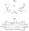
- FIG. 5 is a diagram of an optical submarine transmission system, according to an embodiment of the present invention.
- ground base stations 10 and 20 are interconnected by an optical fiber cable 30.
- Optical amplifier-repeaters 40 1 to 40 (in + 3) are spaced along optical fiber cable 30 at nearly equal intervals, where i and n are positive integers.
- n optical amplifier-repeaters 40 (n) , 40 (2n) , ..., 40 (in) have built-in gain-equalizing filters (not illustrated).
- Each optical amplifier-repeaters 40 1 to 40 (in + 1) , 40 (n + 1) , 40 (n + 2) , and 40 (in + 1) to 40 (in + 3) do not have a built-in gain-equalizing filter.
- Each optical amplifier-repeaters 40 1 to 40 (in + 3) includes an erbium-doped fiber amplifier (EDFA) (not illustrated) for amplification of optical signals.
- EDFA erbium-doped fiber amplifier
- gain-equalizing filters are provided within every n (for example, every ten) amplifier-repeaters.
- These amplifier-repeaters provided with gain-equalizing filters are denoted by 40 (n) , 40 (2n) , and 40 (in) .
- an optical transmission system includes a plurality of optical repeaters arranged along a transmission line.
- a plurality of gain equalizers are also arranged along the transmission line.
- Each gain equalizer is arranged along the transmission line after an integer number of optical repeaters, and equalizes the gain of upstream optical repeaters.
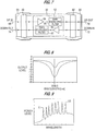
- FIG. 6 is a diagram illustrating a cross-section of an optical amplifier-repeater 401 that does not have a gain-equalizing filter, according to an embodiment of the present invention.
- a cylinder houses an internal unit 52.
- Internal unit 52 includes EDFAs 54 and 56.
- Cylinder 50 is sealed with cover assemblies 60 and 62, which are fitted into the ends of cylinder 50. Further, the ends of cylinder 50 are furnished with joint rings 64 and 66 that cover the cover assemblies 60 and 62.
- An optical signal travelling through an optical fiber 68 is amplified by EDFA 54 and then output to an optical fiber 70.
- An optical signal travelling through optical fiber 72 is amplified by EDFA 56 and then output to optical fiber 74.
- An "X" mark on optical fibers 68, 70, 72, and 74 denotes a splice.
- FIG. 7 is a diagram illustrating a cross-section of an optical amplifier-repeater (such as optical amplifier-repeater 40(n)) having gain-equalizing filters, according to an embodiment of the present invention.
- internal unit 52 is contained in cylinder 50.
- Internal unit 52 includes optical circuits including EDFAs 54 and 56 and gain-equalizing filters 55 and 57.
- Cylinder 50 is sealed with cover assemblies 60 and 62, which are fitted into both ends of the cylinder 50. Further, the ends of cylinder 50 are furnished with joint rings 64 and 66 that cover the cover assemblies 60 and 62.
- optical signal travelling through optical fiber 68 is amplified by EDFA 54, equalized by gain-equalizing filter 55 and then output to optical fiber 70.
- An optical signal travelling through optical fiber 72 is amplified by EDFA 56, equalized by gain-equalizing filter 57 and then output to optical fiber 74.
- the "X" mark on the optical fibers 68, 70, 72, and 74 denotes a splice.
- FIG. 8 is a graph illustrating a characteristic curve of gain-equalizing filters 55 and 57, according to an embodiment of the present invention.
- gain-equalizing filters 55 and 57 each have a notch-shaped characteristic curve having an attenuation valley at a wavelength of approximately 1558.5 nm. This characteristic curve is opposite that of the combination of n EDFAs connected in series.
- FIG. 9 is a graph illustrating a wavelength division multiplexed (WDM) signal having eight wavelength signals ⁇ 1 to ⁇ 8 multiplexed together, after being transmitted through an optical transmission system having gain-equalizing filters, according to an embodiment of the present invention.
- WDM wavelength division multiplexed
- FIG. 9 the optical signal-to-noise ratios (SNRs) of all wavelength ⁇ 1 to ⁇ 8 is significantly increased, compared to a transmission system as illustrated in FIG. 4.
- an optical transmission system such as that shown in FIG. 5, includes a mixture of optical amplifier-repeaters that have gain-equalizing filters and optical amplifier-repeaters that do not have gain-equalizing filters.
- This type of optical transmission system requires two different types of spare optical amplifier-repeaters, one which has a gain-equalizing filter and one which does not have a gain-equalizing filter. If, for example, the system contains approximately seventy (70) repeaters, it is necessary to provide approximately three (3) spare repeaters having gain-equalizing filters and approximately two (2) spare repeaters that do not have gain-equalizing filters. This is a relatively high number of spare repeaters. As a result, the overall cost of the optical transmission system will be relatively high.
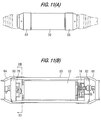
- FIG. 10 is a diagram illustrating an optical amplifier-repeater, according to an embodiment of the present invention.
- FIGS. 11(A) and 11(B) are side and cross-sectional views, respectively, of the optical amplifier-repeater in FIG. 10, according to an embodiment of the present invention.
- internal unit 52 is contained in cylinder 50.
- Internal unit 52 includes EDFAs 54 and 56 and gain-equalizing filters 55 and 57.
- Cylinder 50 is sealed with cover assemblies 60 and 62 which are fitted into both ends of cylinder 50. Further, the ends of cylinder 50 are furnished with joint rings 64 and 66 that cover the cover assemblies 60 and 62.
- the output of EDFA 54, and both the input and output of gain-equalizing filter 55, are carried by optical fibers drawn into a surplus-length fiber holder 78 external to internal unit 52.
- the output of EDFA 56, and the input and output of gain-equalizing filter 57, are carried by optical fibers drawn into a surplus-length fiber holder 76 external to internal unit 52.
- FIG. 12 is a diagram illustrating a view along the direction XII-XII in FIG. 11(B). Therefore, FIG. 12 shows surplus-length fiber holder 76 when viewed from internal unit 52.
- surplus-length fiber is wound inside cylinder 50 for approximately, for example, eighty (80) turns.
- a field-through assembly 82 passes through cover assembly 60.
- An optical fiber tube 82 containing a bundle of optical fibers is introduced through field-through assembly 82 from outside cover assembly 60.
- an optical fiber introduced from outside is spliced to an optical fiber drawn from internal unit 52.
- the splice is supported and fixed by support members 86 and 88.
- the spare optical amplifier-repeater illustrated in FIGS. 10, 11(A) and 11(B) can be used as an optical amplifier-repeater without a gain-equalizing filter. This can be done by appropriately configuring the EDFAs and the gain-equalizing filters so that they are not optically connected together. For example, referring to FIG. 10, an optical fiber connected to the output of EDFA 54 is spliced to optical fiber 70 by surplus-length fiber holder 78, thereby bypassing gain-equalizing filter 55.
- the spare optical amplifier-repeater can also be used as an optical amplifier-repeater containing gain-equalizing filters. This can be done by appropriately configuring the EDFAs and the gain-equalizing filters so that they are optically connected together. For example, referring to FIG. 10, an optical fiber connected to the output of EDFA 56 is spliced to an optical fiber connected to the input of gain-equalizing filter 57. Also, an optical fiber connected to the output of gain-equalizing filter 57 is spliced to optical fiber 74 in surplus-length fiber holder 76. As a result, optical fibers from multiple optical circuits can be selectively connected at surplus-length fiber holders 76 and 78.
- a spare optical amplifier-repeater as shown in FIG. 10 can be used with or without gain-equalizing filters. Whether or not to use the gain-equalizing filters is easily selectable by using the splices on the optical fibers in joint rings 64 and 66. In an optical transmission system that requires approximately seventy (70) repeaters, all that is needed is to provide about three of such spare optical amplifier-repeaters. This is a relatively small amount of spare repeaters, thereby reducing the complexity and cost of the optical transmission system.
- a configuration as illustrated, for example, in FIG. 7, can be used for optical amplifier-repeaters 40(n), 40(2n), ..., 40(in) having built-in gain-equalizing filters.
- an optical repeater includes an optical amplifier, a gain equalizer and a connection mechanism.
- the connection mechanism has a first state and a second state so that (a) when the connection mechanism is in the first state, the gain equalizer of the optical repeater performs an equalization process on a light signal, and (b) when the connection mechanism is in the second state, the gain equalizer of the optical repeater does not perform an equalization process on the light signal.
- FIGS. 10, 11(A) and 11(B an optical repeater includes an optical amplifier, a gain equalizer and a connection mechanism.
- the connection mechanism has a first state and a second state so that (a) when the connection mechanism is in the first state, the gain equalizer of the optical repeater performs an equalization process on a light signal, and (b) when the connection mechanism is in the second state, the gain equalizer of the optical repeater does not perform an equalization process on the light signal.
- surplus-length fiber holders 76 and 78 together operated as a connection mechanism to provide the first state and the second state, by allowing various fibers to be spliced together in an appropriate manner.
- optical switches can be used as a connection mechanism to switch between a state where the gain equalizer and the optical amplifier are optically connected together and a state where the gain equalizer and the optical amplifier are not optically connected together.
- FIG. 13 is a diagram illustrating a cross-section of an optical amplifier-repeater having gain-equalizing filters, according to an additional embodiment of the present invention.
- optical circuits such as optical amplifiers and gain-equalizing filters
- FIG. 12 optical fibers from optical amplifier-repeaters and gain-equalizing filters are selectively connected in surplus-length fiber holders 64 and 66.
- the optical amplifier-repeater includes a first housing 200 and a second housing 300.
- First housing 200 and second housing 300 are both preferably constructed to be air-tight.
- Cylinder 50 in first housing 200 includes an optical amplifier and a gain-equalizing filter.
- Optical fibers drawn out of the optical amplifier, the gain equalizer, and other optical components included in cylinder 50 are led to second housing 300 by a feeder 34 laid out in the form of a pipeline.
- Second housing 300 includes a coupling 91, a universal joint 100 providing a link between first housing 200 and second housing 300, and a polyethylene housing 90 having a surplus-length optical fiber holder which can accommodate the surplus post-connection lengths of the optical fibers.
- a joint ring 66 joins first housing 200 to second housing 300.
- Polyethylene housing 90 contains a surplus-length of optical fiber 80 on which a splicing point is provided so that multiple optical fibers 73 from within tube-like feeder 34 coming from first housing 200 can be selectively connected to optical fibers 71 from a submarine cable.
- the multiple optical fibers 73 are connected to optical circuits (such as optical amplifiers and gain-equalizing filters).
- the surplus-length of optical fiber 80 on which this splicing point is provided is used to lead the output of the optical amplifier to the input of the gain equalizer, and to connect the output fiber of the gain equalizer to the optical fiber from the optical fiber cable 30.
- the surplus-length of optical fiber 80 can directly connect to the optical fiber from optical fiber cable 30 without the intervention of a gain equalizer.
- FIG. 13 also illustrates feeders 31, 32 and 33.
- Optical amplifier-repeaters used in submarine communication systems must endure more extensive reliability tests than ground repeaters. Without the present invention, an optical communication system that contains a mixture of optical amplifier-repeaters that require gain equalizing and those that do not require gain equalizing would need two types of products for optical amplification and repeating. Testing of two types of products would also be necessary. In addition, if an optical amplifier-repeater malfunctions after it is installed underwater, it is extremely difficult to determine whether it is equipped with gain equalizers. Therefore, it would be necessary to provide both types of spare amplifier-repeaters for each installed amplifier-repeater.
- the above embodiments of the present invention allows the first and second housings to be manufactured in advance so that the gain-equalizing filter can be connected as necessary, thus contributing to improved manufacturing.
- the above embodiments of the present invention use the same structure for several types of optical amplifier-repeaters regardless of whether they are equipped with gain-equalizing filters. As a consequence, the number of spare components required after submarine installation is reduced by sharing the same type of repeater. The resulting equipment is thus cost-effective.
- the following embodiment of the present invention demonstrates that the usefulness of the present invention is not limited to optical repeaters that perform optical amplification and gain equalization.
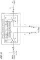
- FIG. 14 is a diagram illustrating an add/drop apparatus which performs optical add/drop processing.
- the apparatus includes an input optical fiber 1 to receive a WDM signal, and an output optical fiber 2 to output the WDM signal after add/drop processing.
- An optical fiber 3 is to output a dropped wavelength signal to an add/drop terminal.
- An optical fiber 4 is to receive a new wavelength signal from the add/drop terminal.
- An optical filter circuit 7 includes an optical isolator 7-1, a first fiber grating filter 7-2 and a second fiber grating filter 7-3.
- a first optical circulator 5 and a second optical circulator 6 are for directing various optical signals to the proper destination. Generally, first and second optical circulators 5 and 6 cyclically pass light in only one direction.
- An "X" mark denotes a splice, and indicates a connecting point between a cable and the add/drop apparatus.
- a WDM signal is received from a first terminal (not illustrated) through optical fiber 1.
- the WDM signal comprises optical signals (also referred to herein as "wavelength signals") with different wavelengths.
- Optical filter circuit 7 isolates certain wavelengths from the WDM signal. Moreover, optical filter 7 can multiplex certain wavelengths from the add/drop terminal to the WDM signal.
- multiple wavelength signals from the first terminal are wavelength-multiplexed to a single WDM signal that is delivered to the optical add/drop apparatus through optical fiber 1.
- the WDM signal goes through the path from a to b of optical circulator 5 and is fed to filter circuit 7.
- first fiber grating filter 7-2 When the WDM signal is passed through filter circuit 7, only the wavelength signal with the wavelength to be sent to the add/drop terminal is reflected by first fiber grating filter 7-2. This reflected wavelength signal then travels through the path from b to c of first optical circulator 5, and is delivered to the add/drop terminal through optical fiber 3.
- a new wavelength signal with the selected wavelength from the add/drop terminal is delivered to the add/drop apparatus through optical fiber 4.
- This new wavelength signals travels through the path from a to b of optical circulator 6 and is delivered to filter circuit 7.
- the new wavelength signal is then reflected by second fiber grating filter 7-3 in filter circuit 7, combined with the WDM signal passing through optical isolator 7-1 in filter circuit 7, then delivered to a second terminal (not illustrated) through optical fiber 2.
- FIG. 15 is a diagram illustrating an optical communication system utilizing add/drop apparatuses.
- systems 1 and 2 transmit WDM signals between terminal stations A and B.
- Each WDM signal includes four wavelength signals at wavelengths ⁇ 1 to ⁇ 4, respectively.
- Add/drop terminals C, D and F receive dropped wavelength signals and provide new wavelength signals, and require the use of three add/drop apparatuses BU1 to BU3.
- each add/drop apparatus BU1 to BU3 is configured as illustrated in FIG. 14.
- one type of add/drop apparatus must be manufactured and provided for each wavelength because each add/drop apparatus includes an optical filter that can handle only one wavelength. If systems 1 and 2 have wavelength signals of different wavelengths to be added/dropped, the number of types of optical add/drop apparatuses will be further increased.
- a solution to these problems is to standardize the structures of the optical add/drop apparatuses used in an optical transmission system that transmits WDM signals over optical fibers between first and second terminals. This minimizes the number of spare optical add/drop apparatuses required, thus contributing to an improvement in system maintainability.
- FIG. 16 is a diagram illustrating an add/drop apparatus, according to an embodiment of the present invention.
- This add/drop apparatus provides a standard configuration which can be used to add/drop many different wavelength signals from a WDM signal.
- WDM signals are received on input optical fibers 1 and 1' for system 1 (SYS1) and system 2 (SYS2), respectively.
- Add/drop processed WDM signals are output for systems 1 and 2 on output optical fibers 2 and 2', respectively.
- Optical fibers 3 and 3' are to output dropped wavelength signals from systems 1 and 2, respectively, to the add/drop terminal.
- Optical fibers 4 and 4' are to receive new wavelength signals for systems 1 and 2, respectively, from the add/drop terminal.
- An optical filter circuit 7 includes optical filters 7-41 to 7-46.
- Each optical filter 7-41 to 7-46 includes a first fiber grating filter, a second fiber grating filter and an optical isolator.
- optical filters 7-41 to 7-46 include input fiber grating filters 7-21 to 7-26, respectively.
- Optical filters 7-41 to 7-46 include output fiber grating filters 7-31 to 7-36, respectively.
- Optical filters 7-41 to 7-46 include optical isolators 7-11 to 7-16, respectively.
- First optical circulator 5 and second optical circulator 6 direct the various optical signals.
- the apparatus also includes an input link 8-1, an output link 8-2, an equipment housing 14, an input port 15, an output port 16 and an add/drop port 17.
- An "X" mark denotes a splice.
- optical filter circuit 7 includes optical filters 7-41 to 7-46 which each reflect only wavelength signals with certain wavelengths out of multiple wavelengths ( ⁇ 1 to ⁇ 6).
- optical filter circuit 7 should included optical filters to cover all the wavelengths in an optical communication system which may be subject to add/drop processing. Therefore, in FIG. 16, optical filter circuit 7 includes optical filters 7-41 to 7-46 to cover the wavelengths ⁇ 1 to ⁇ 6, respectively, that are subject to add/drop processing within the system.
- Light with wavelength ⁇ 1 is reflected by input fiber grating filter 7-21 and output fiber grating filter 7-31 in optical filter 7-41.
- Light with wavelength ⁇ 2 is reflected by input fiber grating filter 7-22 and output fiber grating filter 7-32 in optical filter 7-42.
- Light with wavelength ⁇ 3 is reflected by input fiber grating filter 7-23 and output fiber grating filter 7-33 in optical filter 7-43.
- Light with wavelength ⁇ 4 is reflected by input fiber grating filter 7-24 and output fiber grating filter 7-34 in optical filter 7-44.
- Light with wavelength ⁇ 5 is reflected by input fiber grating filter 7-25 and output fiber grating filter 7-35 in optical filter 7-45.
- Light with wavelength ⁇ 6 is reflected by input fiber grating filter 7-26 and output fiber grating filter 7-36 in optical filter 7-46.
- the input/output fibers and through-fibers on optical filters 7-41 to 7-46 and the input/output fibers on optical circulators 5 and 6 or optical circulators 5' and 6' are laid out so that they can be connected to the optical fibers from the optical circulators when they reach input link 8-1 or output link 8-2 provided outside equipment housing 14.
- FIG. 15 illustrated optical circulators 5 and 6 being optically connected to optical filter 7-44, and optical circulators 5' and 6' being optically connected to optical filter 7-41. Therefore, the WDM signal from optical fiber 1 of system 1 in the cable is fed to optical circulator 5 via input port 15. The WDM signal from optical circulator 5 is fed to optical filter 7-44 in filter circuit 7 via input link 8-1.
- the wavelength signal with wavelength ⁇ 4 is reflected by fiber grating filter 7-24 in optical filter 7-44, is fed to optical circulator 5 via input link 8-1, passes through add/drop port 17, and is then delivered to the add/drop terminal via optical fiber 3.
- optical signal with the selected wavelength from the add/drop terminal is fed to add/drop port 17 via optical fiber 4.
- optical signal fed to add/drop port 17 passes through optical circulator 6 and is delivered to optical filter 7-44 in optical filter circuit 7.
- the wavelength signal with wavelength ⁇ 4 fed to optical filter 7-44 is reflected by output fiber grating filter 7-34, combined with the WDM signal having passed through optical isolator 7-14 in optical filter 7-44, is fed to optical fiber 2, then sent to the second terminal.
- the optical signal from the add/drop terminal may be a WDM signal resulting from the wavelength multiplexing of waves with different wavelengths from the WDM signal in optical fiber 1.
- the wavelength of the wavelength signal reflected by the output fiber grating filter must match the wavelength of the optical signal from the add/drop terminal.
- wavelength signals having wavelengths unequal to ⁇ 4 pass through input fiber grating filter 7-24, optical isolator 7-14, and output fiber grating filter 7-34, and are then output from the apparatus.
- optical add/drop apparatuses in the system can be fabricated with the same design if connections are selectively made from optical circulators 5 and 6 and the optical filters within optical filter circuit 7. These connections can be made in input link 8-1 and output link 8-2.
- An add/drop apparatus as in FIG. 16 can be used for each of the add/drop apparatuses BU1 to BU3 in FIG. 15.
- system 2 is connected to optical filter 7-1. Therefore, regarding a WDM signal travelling in System 2, wavelength signals having wavelengths unequal to ⁇ 1 pass through input fiber grating filter 7-21, optical isolator 7-11, and output fiber grating filter 7-31, and are then output from the apparatus.
- optical fibers are spliced in input link 8-1, output link 8-2, input port 15, output port 16, and add/drop port 17. This layout solves the problem of reflection at joints.
- optical connectors are used to connect optical fibers to input link 8-1, output link 8-2, input port 15, output port 16, and add/drop port 17. This facilitates modification to the connections within input link 8-1 and output link 8-2.
- system 1 uses optical fibers 1 and 2 and System 2 uses optical fibers 1' and 2'.
- These optical fiber cables are used for the transmission of WDM signals resulting from the wavelength multiplexing of multiple wavelength signals with different wavelengths transmitted between multiple terminals.
- optical filter 7-41 can be used exclusively for System 2. This assures effective use of filters.
- the System 1 and System 2 lines may be the inbound and outbound transmission paths, respectively, or vice versa.
- the apparatus does not have to be configured or used for both add/drop processing. Instead, the apparatus can be configured or used for only add processing or only drop processing.
- the term add/drop terminal is not intended to be limited a single, physically connected terminal. Instead, physically separated terminals can function together as an add/drop terminal.
- the apparatus can be used with only an add terminal and/or a drop terminal.
- Equipment housing 14 shown in FIG. 16 may be of the same structure as cylinder 50 shown in FIG. 6. Similarly, input link 8-1, output link 8-2, add/drop port 17, input port 15, and output port 16 can be connected within support members 86 and 88 contained in cover assemblies 60 and 62, as shown in FIG. 12.
- an apparatus can add/drop an individual wavelength signal from a WDM signal.
- the apparatus includes a plurality of filters, and a selection mechanism. Each filter affects a different wavelength.
- the plurality of filters includes at least one filter affecting a wavelength corresponding to a wavelength signal in the WDM signal.
- the selection mechanism selects a respective filter of the at least one filter to allow the apparatus to add/drop the wavelength signal in the WDM signal corresponding to the wavelength of the selected filter.
- input link 8-1 and output link 8-2 together operate as such a selection mechanism.
- FIG. 17 is a diagram illustrating an add/drop apparatus, according to an additional embodiment of the present invention.
- joint boxes 9-1, 9-2 and 9-3 are used for inter-cable connections at the end of cables or extended optical fibers.
- joint box 9-1 includes input link 8-1 and input port 15.
- Joint box 9-2 includes output link 8-2 and output port 16.
- Joint box 9-3 includes add/drop port 17. This configuration makes it possible to selectively connect optical filters 7-41 to 7-46 in optical filter circuit 7.
- Joint boxes 9-1, 9-2, and 9-3 can be constructed in a similar manner as second housing 200 in FIG. 13 because the optical fibers from optical filter circuit 7 and optical circulators 5, 5', 6, and 6' are provided to the feeder in FIG. 13.
- joint boxes 9-1, 9-2, and 9-3 outside the add/drop apparatus by treating the fibers from optical filter circuit 7 and the optical fibers from optical circulators 5, 5', 6, and 6', as cables. Therefore, the equipment can be built so that joint boxes 9-1, 9-2, and 9-3 are provided in optical repeaters which are located before or after the optical add/drop apparatus.
- the present embodiment of the present invention is designed so that a spare optical add/drop apparatus can be stored in the condition that any cumbersome coupling has already been completed. All that must be done at the time of use is to switch connections on the optical filter circuit by simply reconnecting the optical fibers in the joint boxes. In the configuration shown in FIG. 17, it is preferable to use splicing or optical connectors at the connections.
- FIG. 18 is a diagram illustrating an add/drop apparatus, according to a further embodiment of the present invention.
- optical switches 11-1 and 11-2 and control circuit 12 are used to select an appropriate optical filters 7-41 to 7-4n.
- Optical filters 7-41 to 7-4n can extract wavelength signals with specific wavelengths from the WDM signal resulting from the wavelength multiplexing of multiple optical wavelength signals, and can combine wavelength signals having specific wavelengths.
- Optical circulators 5 and 6 cyclically pass optical signals only in one direction.
- Optical switches 11-1 and 11-2 change connections between optical circulators 5 and 6 and optical filters 7-41 to 7-4n.
- An optical amplifier 13 amplifies the WDM signal received into the apparatus.
- Control circuit 12 controls switching of optical switches 11-1 and 11-2.
- a WDM signal from the first terminal is fed to the apparatus via optical fiber 1.
- the WDM signal then travels through a path from a to b of optical circulator 5 and is fed to optical filter circuit 7 via optical switch 11-1.
- wavelength signal with the wavelength to be sent to the add/drop terminal is reflected by a certain optical filter, such as optical filter 7-41, in optical filter circuit 7. This reflected wavelength signal then travels along a path from b to c of optical circulator 5, and is delivered to the add/drop terminal.
- a control signal is sent from control circuit 12 to change the wavelength to be chosen or change optical switches 11-1 and/or 11-2 from the first or second terminal. By sending this signal, control circuit 12 changes optical switches 11-1 and 11-2 to choose the wavelength signal with the desired wavelength.
- Control circuit 12 preferably relies on monitoring/control signals being sent from the terminals connected to the add/drop apparatus, to change optical switches 11-1 and 11-2.
- an apparatus can add/drop an individual wavelength signal from a WDM signal.
- the apparatus includes a plurality of filters, and a selection mechanism. Each filter affects a different wavelength.
- the plurality of filters includes at least one filter affecting a wavelength corresponding to a wavelength signal in the WDM signal.
- the selection mechanism selects a respective filter of the at least one filter to allow the apparatus to add/drop the wavelength signal in the WDM signal corresponding to the wavelength of the selected filter.
- optical switch 11-1, optical switch 11-2 and control circuit 12 together operate as such a selection mechanism.
- an optical filter processes an optical signal by reflecting at least a portion of the optical signal.
- optical fibers 7-41 to 7-46 include fiber grating filters which reflect light.
- the present invention is not intended to be limited to filters which reflect light, and other types of filtering mechanism can be used to appropriately process light signals.
- an add/drop apparatus contains multiple optical filters. It also contains optical switches, an optical amplifier, and control circuits to select the appropriate optical filter. This causes the internal structure of the apparatus to be relatively large, complex, and energy-consuming. However, it is advantageous in that change-over at the time of failure can be performed under control from terminals.
- optical fibers or optical elements are “optically connected” together.
- optical connected is intended to refer to a connection where various fibers or optical elements are connected together so that an optical signal can be transferred through the fibers, or processed by the optical elements. Therefore, for example, if a gain equalizer is "optically connected” to an optical amplifier, a WDM signal can be amplified by the optical amplifier and then travel to the gain equalizer for equalization processing. If the gain equalizer is not “optically connected” to the optical amplifier, the gain equalizer could be considered to be “off-line” so as not to affect the WDM signal.
Landscapes
- Engineering & Computer Science (AREA)
- Computer Networks & Wireless Communication (AREA)
- Signal Processing (AREA)
- Physics & Mathematics (AREA)
- Electromagnetism (AREA)
- Optical Communication System (AREA)
- Lasers (AREA)
Priority Applications (2)
| Application Number | Priority Date | Filing Date | Title |
|---|---|---|---|
| EP04017871A EP1487138B1 (fr) | 1996-10-21 | 1997-10-20 | Appareil comprenant des circuits optiques liés à un câble à fibres optiques |
| EP04017870A EP1471670A3 (fr) | 1996-10-21 | 1997-10-20 | Système de transmission optique incluant un dispositif d'insertion/extraction avec plusieurs filtres sélectionnés individuellement |
Applications Claiming Priority (6)
| Application Number | Priority Date | Filing Date | Title |
|---|---|---|---|
| JP27827896 | 1996-10-21 | ||
| JP8278278A JPH10126384A (ja) | 1996-10-21 | 1996-10-21 | 光分岐/挿入装置 |
| JP278278/96 | 1996-10-21 | ||
| JP06691697A JP3580979B2 (ja) | 1997-03-19 | 1997-03-19 | 光増幅中継器 |
| JP6691697 | 1997-03-19 | ||
| JP66916/97 | 1997-03-19 |
Related Child Applications (2)
| Application Number | Title | Priority Date | Filing Date |
|---|---|---|---|
| EP04017870A Division EP1471670A3 (fr) | 1996-10-21 | 1997-10-20 | Système de transmission optique incluant un dispositif d'insertion/extraction avec plusieurs filtres sélectionnés individuellement |
| EP04017871A Division EP1487138B1 (fr) | 1996-10-21 | 1997-10-20 | Appareil comprenant des circuits optiques liés à un câble à fibres optiques |
Publications (3)
| Publication Number | Publication Date |
|---|---|
| EP0853396A2 true EP0853396A2 (fr) | 1998-07-15 |
| EP0853396A3 EP0853396A3 (fr) | 2001-12-05 |
| EP0853396B1 EP0853396B1 (fr) | 2005-12-28 |
Family
ID=26408121
Family Applications (3)
| Application Number | Title | Priority Date | Filing Date |
|---|---|---|---|
| EP97118169A Expired - Lifetime EP0853396B1 (fr) | 1996-10-21 | 1997-10-20 | Système de transmission optique comportant des répéteurs optiques avec égaliseurs de gain activés sélectivement et contenus dans ces répéteurs et incluant un dispositif d'insertion/extraction avec plusieurs filtres sélectionnés individuellement |
| EP04017871A Expired - Lifetime EP1487138B1 (fr) | 1996-10-21 | 1997-10-20 | Appareil comprenant des circuits optiques liés à un câble à fibres optiques |
| EP04017870A Withdrawn EP1471670A3 (fr) | 1996-10-21 | 1997-10-20 | Système de transmission optique incluant un dispositif d'insertion/extraction avec plusieurs filtres sélectionnés individuellement |
Family Applications After (2)
| Application Number | Title | Priority Date | Filing Date |
|---|---|---|---|
| EP04017871A Expired - Lifetime EP1487138B1 (fr) | 1996-10-21 | 1997-10-20 | Appareil comprenant des circuits optiques liés à un câble à fibres optiques |
| EP04017870A Withdrawn EP1471670A3 (fr) | 1996-10-21 | 1997-10-20 | Système de transmission optique incluant un dispositif d'insertion/extraction avec plusieurs filtres sélectionnés individuellement |
Country Status (2)
| Country | Link |
|---|---|
| US (1) | US6144474A (fr) |
| EP (3) | EP0853396B1 (fr) |
Cited By (15)
| Publication number | Priority date | Publication date | Assignee | Title |
|---|---|---|---|---|
| GB2320828B (en) * | 1996-12-30 | 2001-05-02 | Furukawa Res & Engineering | Isolated multiple grating systems for filtering requirements |
| EP1014606A3 (fr) * | 1998-12-24 | 2001-05-02 | KDD Submarine Cable Systems Inc. | Système de transmission optique et station terminale correspondante |
| US6236487B1 (en) | 1998-07-21 | 2001-05-22 | Corvis Corporation | Optical communication control system |
| US6344925B1 (en) | 2000-03-03 | 2002-02-05 | Corvis Corporation | Optical systems and methods and optical amplifiers for use therein |
| US6356383B1 (en) | 1999-04-02 | 2002-03-12 | Corvis Corporation | Optical transmission systems including optical amplifiers apparatuses and methods |
| US6771859B2 (en) | 2001-07-24 | 2004-08-03 | 3M Innovative Properties Company | Self-aligning optical micro-mechanical device package |
| US6775056B2 (en) | 1998-07-21 | 2004-08-10 | Corvis Corporation | Optical transmission systems including signal varying devices and methods |
| US6798954B2 (en) | 2001-07-24 | 2004-09-28 | 3M Innovative Properties Company | Packaged optical micro-mechanical device |
| US6834154B2 (en) | 2001-07-24 | 2004-12-21 | 3M Innovative Properties Co. | Tooling fixture for packaged optical micro-mechanical devices |
| US6839522B2 (en) | 1998-07-21 | 2005-01-04 | Corvis Corporation | Optical signal varying devices, systems and methods |
| US6941037B2 (en) | 1999-10-22 | 2005-09-06 | Corvis Algety Sa | Optical fiber transmission system using RZ pulses |
| US7085042B2 (en) | 1999-05-24 | 2006-08-01 | Corvis Corporation | Optical transmission systems including optical amplifiers and methods of use therein |
| US7127173B2 (en) | 1999-10-22 | 2006-10-24 | Corvis Algety Sa | Method of adjusting power for a wavelength-division multiplexed optical transmission system |
| US7903978B2 (en) | 1999-05-21 | 2011-03-08 | Broadwing, Llc | Optical transmission systems and amplifier control apparatuses and methods |
| CN110301105A (zh) * | 2017-02-22 | 2019-10-01 | 日本电气株式会社 | 光中继系统 |
Families Citing this family (17)
| Publication number | Priority date | Publication date | Assignee | Title |
|---|---|---|---|---|
| JP3052886B2 (ja) * | 1997-04-25 | 2000-06-19 | 日本電気株式会社 | 光海底利得等化器、光海底伝送路及びその敷設方法 |
| US6552834B2 (en) * | 2000-02-18 | 2003-04-22 | Corning Incorporated | Methods and apparatus for preventing deadbands in an optical communication system |
| US20010046350A1 (en) * | 2000-02-25 | 2001-11-29 | Tedesco James M. | Configurable Wavelength routing device |
| JP2001255423A (ja) * | 2000-03-13 | 2001-09-21 | Furukawa Electric Co Ltd:The | 光部品 |
| JP4588282B2 (ja) * | 2000-08-31 | 2010-11-24 | 富士通株式会社 | 光通信システムの立ち上げ方法およびチャンネル増減設方法、ならびに、コンピュータ読み取り可能な記録媒体 |
| US20020080447A1 (en) * | 2000-12-21 | 2002-06-27 | Julian Fells | Transmission system with enhanced repeaters |
| US6333798B1 (en) | 2001-02-13 | 2001-12-25 | Seneca Networks, Inc. | Bidirectional WDM optical communication network |
| US20030002104A1 (en) * | 2001-06-29 | 2003-01-02 | Caroli Carl A. | Wavelength-selective add/drop arrangement for optical communication systems |
| US6747774B2 (en) | 2001-07-19 | 2004-06-08 | Coadna Photonics, Inc. | Apparatus and method for controlling optical gain profiles |
| US6614572B2 (en) | 2001-07-19 | 2003-09-02 | Coadna Photonics, Inc. | Apparatus and method for controlling optical gain profiles in a temperature independent manner |
| JP2003069116A (ja) * | 2001-08-22 | 2003-03-07 | Fujitsu Ltd | 光増幅器及び利得偏差補償方法 |
| AU2003265935A1 (en) | 2002-05-03 | 2003-11-17 | Harman International Industries, Incorporated | Sound detection and localization system |
| US9246597B2 (en) * | 2010-04-15 | 2016-01-26 | Infinera Corporation | Dual rate QPSK/TCM-QPSK optical modulation |
| WO2017022231A1 (fr) * | 2015-08-03 | 2017-02-09 | 日本電気株式会社 | Dispositif de multiplexage à insertion/extraction optique et procédé de multiplexage à insertion/extraction optique |
| CN108702215B (zh) * | 2016-02-24 | 2021-03-30 | 日本电气株式会社 | 多频带信号处理系统、接线盒、以及用于容纳系统的方法 |
| GB201803543D0 (en) | 2018-03-06 | 2018-04-18 | Neptune Subsea Ip Ltd | Submarine optical system |
| KR102491712B1 (ko) * | 2022-07-07 | 2023-01-27 | (주)엠이엘 텔레콤 | 광섬유 연결성 측정기 |
Family Cites Families (7)
| Publication number | Priority date | Publication date | Assignee | Title |
|---|---|---|---|---|
| IT1184648B (it) * | 1985-06-26 | 1987-10-28 | Pirelli Cavi Spa | Linea sottomarina per telecomunicazioni a firbre ottiche |
| JPS6290043A (ja) * | 1985-10-16 | 1987-04-24 | Nec Corp | 光海底中継器 |
| DE3812143A1 (de) * | 1988-04-12 | 1989-10-26 | Siemens Ag | Verfahren zur identifizierung einzelner lichtwellenleiter innerhalb eines vieladrigen optischen kabels |
| US5225922A (en) * | 1991-11-21 | 1993-07-06 | At&T Bell Laboratories | Optical transmission system equalizer |
| AU664449B2 (en) * | 1992-06-22 | 1995-11-16 | Nec Corporation | Optical communication transmission system |
| FR2731082B1 (fr) * | 1995-02-28 | 1997-04-04 | France Telecom | Multiplexeur optique a insertion-extraction utilisant des circulateurs optiques et des reseaux de bragg photoinscrits |
| FR2738698B1 (fr) * | 1995-09-08 | 1997-10-17 | Alcatel Nv | Procede et systeme d'egalisation des niveaux respectifs de puissance des canaux d'un signal optique spectralement multiplexe |
-
1997
- 1997-10-14 US US08/949,690 patent/US6144474A/en not_active Expired - Lifetime
- 1997-10-20 EP EP97118169A patent/EP0853396B1/fr not_active Expired - Lifetime
- 1997-10-20 EP EP04017871A patent/EP1487138B1/fr not_active Expired - Lifetime
- 1997-10-20 EP EP04017870A patent/EP1471670A3/fr not_active Withdrawn
Cited By (21)
| Publication number | Priority date | Publication date | Assignee | Title |
|---|---|---|---|---|
| GB2320828B (en) * | 1996-12-30 | 2001-05-02 | Furukawa Res & Engineering | Isolated multiple grating systems for filtering requirements |
| US6775056B2 (en) | 1998-07-21 | 2004-08-10 | Corvis Corporation | Optical transmission systems including signal varying devices and methods |
| US6236487B1 (en) | 1998-07-21 | 2001-05-22 | Corvis Corporation | Optical communication control system |
| US6839522B2 (en) | 1998-07-21 | 2005-01-04 | Corvis Corporation | Optical signal varying devices, systems and methods |
| US7046430B2 (en) | 1998-07-21 | 2006-05-16 | Corvis Corporation | Optical transmission systems including signal varying devices and methods |
| EP1014606A3 (fr) * | 1998-12-24 | 2001-05-02 | KDD Submarine Cable Systems Inc. | Système de transmission optique et station terminale correspondante |
| US7133193B2 (en) | 1999-04-02 | 2006-11-07 | Corvis Corporation | Optical transmission systems including optical amplifiers, apparatuses and methods |
| US6771413B2 (en) | 1999-04-02 | 2004-08-03 | Corvis Corporation | Optical transmission systems including optical amplifiers, apparatuses and methods |
| US6356383B1 (en) | 1999-04-02 | 2002-03-12 | Corvis Corporation | Optical transmission systems including optical amplifiers apparatuses and methods |
| US7903978B2 (en) | 1999-05-21 | 2011-03-08 | Broadwing, Llc | Optical transmission systems and amplifier control apparatuses and methods |
| US7085042B2 (en) | 1999-05-24 | 2006-08-01 | Corvis Corporation | Optical transmission systems including optical amplifiers and methods of use therein |
| US7127173B2 (en) | 1999-10-22 | 2006-10-24 | Corvis Algety Sa | Method of adjusting power for a wavelength-division multiplexed optical transmission system |
| US6941037B2 (en) | 1999-10-22 | 2005-09-06 | Corvis Algety Sa | Optical fiber transmission system using RZ pulses |
| US6459529B1 (en) | 2000-03-03 | 2002-10-01 | Corvis Corporation | Optical systems and methods and optical amplifiers for use therein |
| US6704139B2 (en) | 2000-03-03 | 2004-03-09 | Corvis Corporation | Optical systems and methods and optical amplifiers for use therein |
| US6344925B1 (en) | 2000-03-03 | 2002-02-05 | Corvis Corporation | Optical systems and methods and optical amplifiers for use therein |
| US6834154B2 (en) | 2001-07-24 | 2004-12-21 | 3M Innovative Properties Co. | Tooling fixture for packaged optical micro-mechanical devices |
| US6798954B2 (en) | 2001-07-24 | 2004-09-28 | 3M Innovative Properties Company | Packaged optical micro-mechanical device |
| US6771859B2 (en) | 2001-07-24 | 2004-08-03 | 3M Innovative Properties Company | Self-aligning optical micro-mechanical device package |
| CN110301105A (zh) * | 2017-02-22 | 2019-10-01 | 日本电气株式会社 | 光中继系统 |
| EP3588809A4 (fr) * | 2017-02-22 | 2020-02-26 | Nec Corporation | Système de relais optique |
Also Published As
| Publication number | Publication date |
|---|---|
| EP1471670A3 (fr) | 2006-09-20 |
| EP0853396B1 (fr) | 2005-12-28 |
| US6144474A (en) | 2000-11-07 |
| EP1487138B1 (fr) | 2006-06-07 |
| EP0853396A3 (fr) | 2001-12-05 |
| EP1487138A1 (fr) | 2004-12-15 |
| EP1471670A2 (fr) | 2004-10-27 |
Similar Documents
| Publication | Publication Date | Title |
|---|---|---|
| US6144474A (en) | Optical transmission system including optical repeaters with selectively enabled gain equalizers contained therein and including an add/drop apparatus with a plurality of individually selectable filters | |
| US12085771B2 (en) | Submarine cable branching units with fiber pair switching | |
| EP1296470B1 (fr) | Systèmes de transmission optique utilisant des amplificateurs optiques et le multiplexage en longueurs d'ondes | |
| US7136586B2 (en) | Optical communication system | |
| US6556340B1 (en) | Optical amplifiers and upgrade modules | |
| EP2510641B1 (fr) | Gestion de puissance de canal dans système de communication optique ramifié | |
| US5748363A (en) | Wavelength dependent crossover system for bi-directional transmission | |
| EP2297889A1 (fr) | Multiplexeur d'insertion/extraction optique comprenant des filtres reconfigurables et système le comprenant | |
| EP3404855B1 (fr) | Utilisation de filtres passe-bande dans des trajets de signal de surveillance d'un système de transport optique | |
| US6684005B1 (en) | Connection of an add/drop node | |
| US6934442B2 (en) | Undersea branching unit for an undersea optical transmission system | |
| EP1351416B1 (fr) | Système et méthode d'amplification des signaux dans un réseau optique | |
| US6304351B1 (en) | Universal branching unit | |
| US6552834B2 (en) | Methods and apparatus for preventing deadbands in an optical communication system | |
| US11582539B2 (en) | Method and apparatus for management of a spectral capacity of a wavelength division multiplexing system | |
| US7085456B1 (en) | Electrical and optical isolating unit for an undersea branching unit | |
| EP3758257A1 (fr) | Technique permettant de surveiller des trajectoires optiques | |
| JP3580979B2 (ja) | 光増幅中継器 | |
| GB2359434A (en) | Optical wavelength dependent routing interface | |
| JP2001197001A (ja) | 光学装置 | |
| HK1054135B (en) | Optical transmission systems using optical amplifiers and wavelength division multiplexing |
Legal Events
| Date | Code | Title | Description |
|---|---|---|---|
| PUAI | Public reference made under article 153(3) epc to a published international application that has entered the european phase |
Free format text: ORIGINAL CODE: 0009012 |
|
| AK | Designated contracting states |
Kind code of ref document: A2 Designated state(s): AT BE CH DE DK ES FI FR GB GR IE IT LI LU MC NL PT SE Kind code of ref document: A2 Designated state(s): FR GB |
|
| AX | Request for extension of the european patent |
Free format text: AL;LT;LV;RO;SI |
|
| PUAL | Search report despatched |
Free format text: ORIGINAL CODE: 0009013 |
|
| RIC1 | Information provided on ipc code assigned before grant |
Free format text: 7H 04B 10/18 A, 7H 04B 10/17 B, 7H 04J 14/02 B, 7H 04Q 11/00 B, 7G 02B 6/04 B |
|
| AK | Designated contracting states |
Kind code of ref document: A3 Designated state(s): AT BE CH DE DK ES FI FR GB GR IE IT LI LU MC NL PT SE |
|
| AX | Request for extension of the european patent |
Free format text: AL;LT;LV;RO;SI |
|
| 17P | Request for examination filed |
Effective date: 20020529 |
|
| AKX | Designation fees paid |
Free format text: FR GB |
|
| REG | Reference to a national code |
Ref country code: DE Ref legal event code: 8566 |
|
| 17Q | First examination report despatched |
Effective date: 20040408 |
|
| GRAP | Despatch of communication of intention to grant a patent |
Free format text: ORIGINAL CODE: EPIDOSNIGR1 |
|
| GRAS | Grant fee paid |
Free format text: ORIGINAL CODE: EPIDOSNIGR3 |
|
| GRAA | (expected) grant |
Free format text: ORIGINAL CODE: 0009210 |
|
| AK | Designated contracting states |
Kind code of ref document: B1 Designated state(s): FR GB |
|
| REG | Reference to a national code |
Ref country code: GB Ref legal event code: FG4D |
|
| ET | Fr: translation filed | ||
| PLBE | No opposition filed within time limit |
Free format text: ORIGINAL CODE: 0009261 |
|
| STAA | Information on the status of an ep patent application or granted ep patent |
Free format text: STATUS: NO OPPOSITION FILED WITHIN TIME LIMIT |
|
| 26N | No opposition filed |
Effective date: 20060929 |
|
| PGFP | Annual fee paid to national office [announced via postgrant information from national office to epo] |
Ref country code: GB Payment date: 20101020 Year of fee payment: 14 |
|
| PGFP | Annual fee paid to national office [announced via postgrant information from national office to epo] |
Ref country code: FR Payment date: 20111103 Year of fee payment: 15 |
|
| GBPC | Gb: european patent ceased through non-payment of renewal fee |
Effective date: 20121020 |
|
| REG | Reference to a national code |
Ref country code: FR Ref legal event code: ST Effective date: 20130628 |
|
| PG25 | Lapsed in a contracting state [announced via postgrant information from national office to epo] |
Ref country code: GB Free format text: LAPSE BECAUSE OF NON-PAYMENT OF DUE FEES Effective date: 20121020 |
|
| PG25 | Lapsed in a contracting state [announced via postgrant information from national office to epo] |
Ref country code: FR Free format text: LAPSE BECAUSE OF NON-PAYMENT OF DUE FEES Effective date: 20121031 |