EP0853564B1 - Lame d'essuie-glace pour vehicules a moteur - Google Patents
Lame d'essuie-glace pour vehicules a moteur Download PDFInfo
- Publication number
- EP0853564B1 EP0853564B1 EP97923798A EP97923798A EP0853564B1 EP 0853564 B1 EP0853564 B1 EP 0853564B1 EP 97923798 A EP97923798 A EP 97923798A EP 97923798 A EP97923798 A EP 97923798A EP 0853564 B1 EP0853564 B1 EP 0853564B1
- Authority
- EP
- European Patent Office
- Prior art keywords
- supporting element
- wiper blade
- longitudinal
- longitudinal rails
- blade according
- Prior art date
- Legal status (The legal status is an assumption and is not a legal conclusion. Google has not performed a legal analysis and makes no representation as to the accuracy of the status listed.)
- Expired - Lifetime
Links
- 230000009467 reduction Effects 0.000 claims description 9
- 229910000831 Steel Inorganic materials 0.000 claims description 3
- 239000000463 material Substances 0.000 claims description 3
- 239000010959 steel Substances 0.000 claims description 3
- 230000000087 stabilizing effect Effects 0.000 claims 4
- 239000011521 glass Substances 0.000 claims 2
- 210000000078 claw Anatomy 0.000 description 10
- 239000003381 stabilizer Substances 0.000 description 2
- 229910000639 Spring steel Inorganic materials 0.000 description 1
- 230000015572 biosynthetic process Effects 0.000 description 1
- 230000008859 change Effects 0.000 description 1
- 230000003247 decreasing effect Effects 0.000 description 1
- 239000012530 fluid Substances 0.000 description 1
- 230000008719 thickening Effects 0.000 description 1
- 210000000689 upper leg Anatomy 0.000 description 1
Images

Classifications
-
- B—PERFORMING OPERATIONS; TRANSPORTING
- B60—VEHICLES IN GENERAL
- B60S—SERVICING, CLEANING, REPAIRING, SUPPORTING, LIFTING, OR MANOEUVRING OF VEHICLES, NOT OTHERWISE PROVIDED FOR
- B60S1/00—Cleaning of vehicles
- B60S1/02—Cleaning windscreens, windows or optical devices
- B60S1/04—Wipers or the like, e.g. scrapers
- B60S1/32—Wipers or the like, e.g. scrapers characterised by constructional features of wiper blade arms or blades
- B60S1/38—Wiper blades
- B60S1/3848—Flat-type wiper blade, i.e. without harness
- B60S1/3849—Connectors therefor; Connection to wiper arm; Attached to blade
- B60S1/3851—Mounting of connector to blade assembly
- B60S1/3856—Gripping the blade
-
- B—PERFORMING OPERATIONS; TRANSPORTING
- B60—VEHICLES IN GENERAL
- B60S—SERVICING, CLEANING, REPAIRING, SUPPORTING, LIFTING, OR MANOEUVRING OF VEHICLES, NOT OTHERWISE PROVIDED FOR
- B60S1/00—Cleaning of vehicles
- B60S1/02—Cleaning windscreens, windows or optical devices
- B60S1/04—Wipers or the like, e.g. scrapers
- B60S1/32—Wipers or the like, e.g. scrapers characterised by constructional features of wiper blade arms or blades
- B60S1/38—Wiper blades
- B60S1/3848—Flat-type wiper blade, i.e. without harness
- B60S1/3874—Flat-type wiper blade, i.e. without harness with a reinforcing vertebra
- B60S1/3875—Flat-type wiper blade, i.e. without harness with a reinforcing vertebra rectangular section
- B60S1/3879—Flat-type wiper blade, i.e. without harness with a reinforcing vertebra rectangular section placed in side grooves in the squeegee
Definitions
- the invention is based on a wiper blade according to the Preamble of Claim 1.
- US-A-3,659,310 is a Wiper blade became known in which the contact pressure starting from the wiper arm on a bracket frame on a Wiper strip is transmitted.
- the wiper strip shows Supporting element that is made of special claws subordinate bracket of the bracket system is taken.
- Around the wiper strip, especially the support element simple It is proposed to be able to replace the support element to be hairpin-shaped and with an outer and an inner ramp and an external tooth structure in the Area of the inner ramp.
- With the inner The squeegee becomes a ramp in the support element by pressing the claw of the claw bracket acting from the outside.
- the outer ramp as well as the tooth structure are required around to keep the wiper strip inside the claw bracket.
- This Setup is complex and requires precise coordination of the outer ramp and the tooth structure by a certain To ensure mobility of the squeegee.
- Such a reduction in cross section can also be achieved by achieved a reduction in the thickness of the support element be, the greatest thickness in the central portion of the Supporting element is located.
- bracket of the trained stabilizer it may be appropriate be if these are non-positive or positive with the Longitudinal rails is connected. It goes without saying a powerful and fluid connection possible.
- the longitudinal extension of the support element exceeds a certain level, so that a certain Lability of the longitudinal rails may result in the required Stability of the support element can be ensured that between that at the free ends of the longitudinal rails arranged bracket and one the base of the hairpin shape forming web at least one additional intermediate bracket is arranged, which face away from each other Grips the longitudinal edges of the longitudinal rails with claw attachments.
- a further simplification of the wiper blade results if in an embodiment of the invention, the further bracket with a Connection device for the driven wiper arm Is provided.
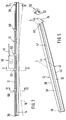
- FIG. 1 shows a side view of an inventive Wiper blade
- Figure 2 shows a section through the wiper blade along the line II - II in Figure 1, with a Perspective middle section of the wiper blade in an enlarged view
- Figure 3 shows a section through the Wiper blade along the line III - III in Figure 1, with a intermediate section shown in perspective
- in 4 shows the sectional area of an enlarged representation Cut through the wiper blade along the line IV - IV in Figure 1, in an enlarged view
- Figure 5 a perspective, to scale representation of a for Wiper blade supporting element and one to this belonging bracket.
- a wiper blade 10 shown in FIG. 1 has one elastic, in the embodiment made of spring steel manufactured support member 12 for one of a wiper strip 14 made of rubber-like material.
- Figure 1 is the elongated wiper blade 10 of the For simplicity, drawn in a position where it is can not be in practice because the elastic Support element is biased so that the wiper strip 14th is curved, as is by a dash-dotted line 16 is indicated in Figure 1.
- This curvature is stronger than the maximum curvature of the to be wiped, as a rule spherically curved motor vehicle window. It means that the wiper blade 10 when applied to the window to be wiped first with its two end areas on the disc Finally, the middle section of the plant also comes Wiper blade rests on the window.
- the Wiper strip 14 has a wiper lip that can be placed on the window 17, which is connected to the body 22 via a so-called tilting web 20 the wiper strip 14 is connected.
- longitudinal grooves 24 and 26 arranged, which extends over the entire length of the elongate wiper strip 14 extend.
- longitudinal rails 28 and 30 of the support element 12 housed, the structure of which can be seen from FIG.
- the support member 12 is made of one Spring band steel manufactured. It has its entire length a uniform thickness 34.
- the support member 12 has the shape a hairpin.
- the described hairpin shape of the support element 12 sees So before that the two longitudinal rails 28 and 30 parallel and are spaced from each other. It follows thus in the support member 12, a longitudinal slot 47 which in Area of the free ends of the longitudinal rails 28 and 30 opens.
- This mouth 48 enables easy assembly of the Wiper strip 14 and support element 12. To do this, only the Wiper strip 14 from the mouth 48 so on the support member 12 are pushed on that the two longitudinal rails 28 and 30 into the longitudinal grooves 24 and 26 of the wiper strip body 22 come to lie ( Figures 2 and 3). In doing so, the wiper strip 14 inserted into the support element up to the web 36. to Securing the wiper strip 14 on the support member 12 is on the free ends of the longitudinal strips 28 and 30 as Stabilizer acting clamp 50 applied.
- the clip 50 will cause some deformation of the wiper body 22 reached, which also a Securing the support element 12 on the wiper strip and a Securing the bracket 50 belonging to the support element 12 the wiper strip 14 is reached.
- it is also one positive locking of the clip 50 on the longitudinal rails 28, 30 and / or on the wiper strip 14 are conceivable.
- FIGS. 1 and 2 Another advantageous embodiment of the intermediate claws 60 can be seen from FIGS. 1 and 2.
Landscapes
- Engineering & Computer Science (AREA)
- Mechanical Engineering (AREA)
- Body Structure For Vehicles (AREA)
- Seal Device For Vehicle (AREA)
- Cleaning In General (AREA)
- Brushes (AREA)
- Transmission Devices (AREA)
Claims (9)
- Balai d'essuie-glace (10) pour des vitres de véhicule, comprenant un raidisseur (12) allongé, élastique, pour recevoir une raclette (14), allongée, réalisée en une matière souple et destinée à s'appliquer contre la vitre à essuyer, cette raclette ayant dans ses grands côtés opposés, des rainures longitudinales (24, 26) recevant des rails longitudinaux (28, 30) du raidisseur (12), ces rails étant écartés l'un de l'autre, et ce raidisseur a une forme d'épingle à cheveux dont les deux branches sont formées par les rails longitudinaux (28, 30), les extrémités libres des branches étant maintenues réunies par un moyen de stabilisation (50) en étant notamment reliées l'une à l'autre,
caractérisé en ce que
le moyen de stabilisation (50) est constitué par un composant séparé, le segment central (42) comporte un dispositif d'accrochage (66) pour le bras d'entraínement (18) et la section des deux rails longitudinaux va en diminuant en partant de la zone centrale vers les extrémités des rails. - Balai d'essuie-glace selon la revendication 1,
caractérisé en ce que
la réduction de la section du raidisseur (12) est réalisée par une réduction de la largeur (44, 46) du raidisseur, la plus grande largeur (44) se trouvant au niveau du segment central (42) du raidisseur (12). - Balai d'essuie-glace selon l'une quelconque des revendications 1 ou 2,
caractérisé en ce que
la réduction de section du raidisseur (12) correspond à une réduction de l'épaisseur (34) de l'élément de support et la plus grande épaisseur (34) se trouve dans le segment central (42) du raidisseur (12). - Balai d'essuie-glace selon l'une quelconque des revendications 1 à 3,
caractérisé en ce que
les moyens de stabilisation sont réalisés sous la forme d'une pince (50) et les pinces sont reliées par une liaison par la force aux rails longitudinaux (28, 30) du raidisseur (12). - Balai d'essuie-glace selon l'une quelconque des revendications 1 à 3,
caractérisé en ce que
les moyens de stabilisation réalisés sous la forme de pinces (50) sont reliés par une liaison de forme aux rails longitudinaux (28, 30) du raidisseur (12). - Balai d'essuie-glace selon l'une quelconque des revendications 1 à 5,
caractérisé par
au moins une pince intermédiaire (60) entre les pinces (50) prévues aux extrémités libres des rails longitudinaux (28, 30) et l'entretoise (36) qui constitue la base de la forme d'épingle à cheveux. - Balai d'essuie-glace selon la revendication 6,
caractérisé en ce que
la pince (50, 60) entoure les arêtes longitudinales opposées (38, 40) des rails longitudinaux (28, 30) avec des griffes (68). - Balai d'essuie-glace selon l'une quelconque des revendications 6 ou 7,
caractérisé en ce que
la pince intermédiaire (60) est munie d'un dispositif d'accrochage (66) pour le bras d'entraínement (18). - Balai d'essuie-glace selon l'une quelconque des revendications 1 à 8,
caractérisé en ce que
le raidisseur (12) est réalisé dans un ruban d'acier à ressort.
Applications Claiming Priority (3)
| Application Number | Priority Date | Filing Date | Title |
|---|---|---|---|
| DE19627114 | 1996-07-05 | ||
| DE1996127114 DE19627114A1 (de) | 1996-07-05 | 1996-07-05 | Wischblatt für Scheiben von Kraftfahrzeugen |
| PCT/DE1997/000947 WO1998001326A1 (fr) | 1996-07-05 | 1997-05-10 | Lame d'essuie-glace pour vehicules a moteur |
Publications (2)
| Publication Number | Publication Date |
|---|---|
| EP0853564A1 EP0853564A1 (fr) | 1998-07-22 |
| EP0853564B1 true EP0853564B1 (fr) | 2002-01-16 |
Family
ID=7799029
Family Applications (1)
| Application Number | Title | Priority Date | Filing Date |
|---|---|---|---|
| EP97923798A Expired - Lifetime EP0853564B1 (fr) | 1996-07-05 | 1997-05-10 | Lame d'essuie-glace pour vehicules a moteur |
Country Status (6)
| Country | Link |
|---|---|
| EP (1) | EP0853564B1 (fr) |
| JP (1) | JPH11512994A (fr) |
| CN (1) | CN1114538C (fr) |
| DE (2) | DE19627114A1 (fr) |
| ES (1) | ES2170952T3 (fr) |
| WO (1) | WO1998001326A1 (fr) |
Families Citing this family (15)
| Publication number | Priority date | Publication date | Assignee | Title |
|---|---|---|---|---|
| DE19856300A1 (de) * | 1998-12-07 | 2000-06-08 | Bosch Gmbh Robert | Wischblatt für Scheiben von Kraftfahrzeugen |
| DE19860644A1 (de) * | 1998-12-29 | 2000-07-06 | Bosch Gmbh Robert | Vorrichtung zum gelenkigen Verbinden eines Wischblatts für Scheiben von Kraftfahrzeugen mit einem Wischerarm und Verfahren zum Herstellen dieser Verbindung |
| DE19907629A1 (de) * | 1999-02-23 | 2000-08-24 | Bosch Gmbh Robert | Vorrichtung zum gelenkigen Verbinden eines Wischblatts für Scheiben von Kraftfahrzeugen mit einem Wischerarm |
| DE19909971A1 (de) * | 1999-03-06 | 2000-09-07 | Bosch Gmbh Robert | Wischblatt zum Reinigen von Fahrzeugscheiben und Verfahren zum Montieren des Wischblatts |
| DE10025706A1 (de) * | 2000-05-25 | 2001-11-29 | Bosch Gmbh Robert | Wischblatt zum Reinigen von Fahrzeugscheiben |
| DE10025708A1 (de) * | 2000-05-25 | 2001-11-29 | Bosch Gmbh Robert | Wischblatt zum Reinigen von Fahrzeugscheiben |
| DE10038992B4 (de) * | 2000-08-10 | 2015-10-08 | Valeo Auto-Electric Wischer Und Motoren Gmbh | Wischvorrichtung |
| DE10043427B4 (de) * | 2000-09-04 | 2010-09-23 | Valeo Wischersysteme Gmbh | Wischvorrichtung |
| DE10120467A1 (de) | 2001-04-26 | 2002-10-31 | Bosch Gmbh Robert | Wischblatt zum Reinigen von Scheiben, insbesondere von Kraftfahrzeugen |
| JP4202940B2 (ja) * | 2003-06-13 | 2008-12-24 | アスモ株式会社 | ワイパブレード |
| DE102008000708A1 (de) * | 2008-03-17 | 2009-09-24 | Robert Bosch Gmbh | Wischblatt |
| CN101780790B (zh) * | 2009-01-15 | 2011-06-22 | 张继鸿 | 可稳定刮条的雨刷 |
| PL2233375T3 (pl) * | 2009-03-25 | 2014-07-31 | Unipoint Electric Mfg Co Ltd | Konstrukcja pióra wycieraczki przedniej szyby |
| WO2011134502A1 (fr) * | 2010-04-28 | 2011-11-03 | Federal-Mogul S.A. | Dispositif d'essuie-glace |
| CN112572359B (zh) * | 2020-12-01 | 2024-06-11 | 贵阳万江航空机电有限公司 | 一种长度大于550mm的六爪塑料骨架雨刮片 |
Family Cites Families (5)
| Publication number | Priority date | Publication date | Assignee | Title |
|---|---|---|---|---|
| US3192551A (en) * | 1964-08-31 | 1965-07-06 | Walter D Appel | Windshield wiper blade assembly |
| US3659310A (en) * | 1970-06-03 | 1972-05-02 | Wypco Corp The | Spine piece for squeegee blades |
| IT1032660B (it) * | 1975-04-11 | 1979-06-20 | Arman Sas Di Dario Arman Ec | Supporto lamellare per spazzole tergenti negli impianti tergivetro abordo di autoveicoli in genere |
| DE3827875C2 (de) * | 1988-08-13 | 1999-05-12 | Teves Gmbh Alfred | Ersatzwischleiste und Montageverfahren dazu |
| FR2716853B1 (fr) * | 1994-03-01 | 1996-04-19 | Valeo Systemes Dessuyage | Balai d'essuie-glace comportant des moyens perfectionnés d'immobilisation longitudinale de la raclette de renfort. |
-
1996
- 1996-07-05 DE DE1996127114 patent/DE19627114A1/de not_active Withdrawn
-
1997
- 1997-05-10 DE DE59706012T patent/DE59706012D1/de not_active Expired - Lifetime
- 1997-05-10 EP EP97923798A patent/EP0853564B1/fr not_active Expired - Lifetime
- 1997-05-10 WO PCT/DE1997/000947 patent/WO1998001326A1/fr not_active Ceased
- 1997-05-10 JP JP10504630A patent/JPH11512994A/ja active Pending
- 1997-05-10 ES ES97923798T patent/ES2170952T3/es not_active Expired - Lifetime
- 1997-05-10 CN CN97190852A patent/CN1114538C/zh not_active Expired - Fee Related
Also Published As
| Publication number | Publication date |
|---|---|
| CN1114538C (zh) | 2003-07-16 |
| WO1998001326A1 (fr) | 1998-01-15 |
| DE19627114A1 (de) | 1998-01-08 |
| JPH11512994A (ja) | 1999-11-09 |
| EP0853564A1 (fr) | 1998-07-22 |
| CN1197431A (zh) | 1998-10-28 |
| DE59706012D1 (de) | 2002-02-21 |
| ES2170952T3 (es) | 2002-08-16 |
Similar Documents
| Publication | Publication Date | Title |
|---|---|---|
| EP0853566B1 (fr) | Lame d'essuie-glace pour les vitres de vehicules a moteur | |
| EP0853565B1 (fr) | Lame d'essuie-glace pour vitres de vehicules a moteur | |
| EP1140586B1 (fr) | Emballage unitaire pour balai d'essuie-glace pour vitres d'automobiles, place au moins en partie dans ledit emballage | |
| EP0850163B1 (fr) | Balai d'essuie-glace | |
| EP0624133B1 (fr) | Ensemble balai d'essuie-glace pour le nettoyage des vitres de vehicules automobiles | |
| DE19833666B4 (de) | Wischblatt für Scheiben von Kraftfahrzeugen | |
| EP1547883B1 (fr) | Balai d'essuie-glace pour nettoyer des pare-brise de vehicules | |
| EP1332075B1 (fr) | Dispositif de connexion articulee amovible d'un balai d'essuie-glace destine au nettoyage de vitres avec un bras d'essuie-glace | |
| EP1053145B1 (fr) | Raclette d'essuie-glace pour des vitres de vehicules automobiles | |
| EP0853564B1 (fr) | Lame d'essuie-glace pour vehicules a moteur | |
| EP0935546A1 (fr) | Essuie-glace destine au nettoyage de vitres de vehicules automobiles | |
| EP1289804A1 (fr) | Raclette d'essuie-glace pour le nettoyage de vitres de vehicules | |
| EP1289806A1 (fr) | Raclette d'essuie-glace pour le nettoyage de vitres, notamment de vehicules automobiles | |
| DE10065014A1 (de) | Wischvorrichtung, insbesondere für Scheiben von Kraftfahrzeugen | |
| EP0810936A1 (fr) | Ensemble raclette d'essuie-glace pour pare-brise de vehicule a moteur | |
| EP0847346B1 (fr) | Lame d'essuie-glace a brise-vent pour systemes essuie-glace de vehicules a moteur | |
| DE4320637A1 (de) | Scheibenwischblatt mit einem mehrgliedrigen Tragbügelgestell | |
| EP0816194B1 (fr) | Raclette d'essuyage pour pare-brise de véhicule automobile | |
| DE10228494A1 (de) | Wischblatt zum Reinigen von Fahrzeugscheiben sowie ein Wischhebel an dessen Wischerarm ein solches Wischblatt angelenkt ist | |
| EP0930991A1 (fr) | Raclette d'essuie-glace pour le nettoyage de vitres de vehicules automobiles | |
| DE69303107T2 (de) | Scheibenwischanlage mit Windableiter | |
| EP0499829B1 (fr) | Installation d'essuyage pour vitres des véhicules automobiles | |
| DE10312979A1 (de) | Wischblatt zum Reinigen von Scheiben insbesondere von Kraftfahrzeugen | |
| DE19959259B4 (de) | Wischblatt zum Reinigen von Scheiben an Kraftfahrzeugen | |
| WO2002012035A1 (fr) | Dispositif d'essuie-glace, notamment pour automobiles |
Legal Events
| Date | Code | Title | Description |
|---|---|---|---|
| PUAI | Public reference made under article 153(3) epc to a published international application that has entered the european phase |
Free format text: ORIGINAL CODE: 0009012 |
|
| AK | Designated contracting states |
Kind code of ref document: A1 Designated state(s): DE ES FR GB IT |
|
| 17P | Request for examination filed |
Effective date: 19980715 |
|
| 17Q | First examination report despatched |
Effective date: 20000320 |
|
| GRAG | Despatch of communication of intention to grant |
Free format text: ORIGINAL CODE: EPIDOS AGRA |
|
| GRAG | Despatch of communication of intention to grant |
Free format text: ORIGINAL CODE: EPIDOS AGRA |
|
| GRAH | Despatch of communication of intention to grant a patent |
Free format text: ORIGINAL CODE: EPIDOS IGRA |
|
| GRAH | Despatch of communication of intention to grant a patent |
Free format text: ORIGINAL CODE: EPIDOS IGRA |
|
| GRAA | (expected) grant |
Free format text: ORIGINAL CODE: 0009210 |
|
| REG | Reference to a national code |
Ref country code: GB Ref legal event code: IF02 |
|
| AK | Designated contracting states |
Kind code of ref document: B1 Designated state(s): DE ES FR GB IT |
|
| REF | Corresponds to: |
Ref document number: 59706012 Country of ref document: DE Date of ref document: 20020221 |
|
| GBT | Gb: translation of ep patent filed (gb section 77(6)(a)/1977) |
Effective date: 20020406 |
|
| ET | Fr: translation filed | ||
| REG | Reference to a national code |
Ref country code: ES Ref legal event code: FG2A Ref document number: 2170952 Country of ref document: ES Kind code of ref document: T3 |
|
| PLBE | No opposition filed within time limit |
Free format text: ORIGINAL CODE: 0009261 |
|
| STAA | Information on the status of an ep patent application or granted ep patent |
Free format text: STATUS: NO OPPOSITION FILED WITHIN TIME LIMIT |
|
| 26N | No opposition filed | ||
| PGFP | Annual fee paid to national office [announced via postgrant information from national office to epo] |
Ref country code: GB Payment date: 20050425 Year of fee payment: 9 |
|
| PGFP | Annual fee paid to national office [announced via postgrant information from national office to epo] |
Ref country code: FR Payment date: 20050519 Year of fee payment: 9 |
|
| PGFP | Annual fee paid to national office [announced via postgrant information from national office to epo] |
Ref country code: ES Payment date: 20050531 Year of fee payment: 9 |
|
| PG25 | Lapsed in a contracting state [announced via postgrant information from national office to epo] |
Ref country code: GB Free format text: LAPSE BECAUSE OF NON-PAYMENT OF DUE FEES Effective date: 20060510 |
|
| PG25 | Lapsed in a contracting state [announced via postgrant information from national office to epo] |
Ref country code: ES Free format text: LAPSE BECAUSE OF NON-PAYMENT OF DUE FEES Effective date: 20060511 |
|
| PGFP | Annual fee paid to national office [announced via postgrant information from national office to epo] |
Ref country code: IT Payment date: 20060531 Year of fee payment: 10 |
|
| GBPC | Gb: european patent ceased through non-payment of renewal fee |
Effective date: 20060510 |
|
| REG | Reference to a national code |
Ref country code: FR Ref legal event code: ST Effective date: 20070131 |
|
| REG | Reference to a national code |
Ref country code: ES Ref legal event code: FD2A Effective date: 20060511 |
|
| PG25 | Lapsed in a contracting state [announced via postgrant information from national office to epo] |
Ref country code: FR Free format text: LAPSE BECAUSE OF NON-PAYMENT OF DUE FEES Effective date: 20060531 |
|
| PG25 | Lapsed in a contracting state [announced via postgrant information from national office to epo] |
Ref country code: IT Free format text: LAPSE BECAUSE OF NON-PAYMENT OF DUE FEES Effective date: 20070510 |
|
| PGFP | Annual fee paid to national office [announced via postgrant information from national office to epo] |
Ref country code: DE Payment date: 20130723 Year of fee payment: 17 |
|
| REG | Reference to a national code |
Ref country code: DE Ref legal event code: R119 Ref document number: 59706012 Country of ref document: DE |
|
| REG | Reference to a national code |
Ref country code: DE Ref legal event code: R119 Ref document number: 59706012 Country of ref document: DE Effective date: 20141202 |
|
| PG25 | Lapsed in a contracting state [announced via postgrant information from national office to epo] |
Ref country code: DE Free format text: LAPSE BECAUSE OF NON-PAYMENT OF DUE FEES Effective date: 20141202 |