EP0853746B1 - Vorrichtung und verfahren zur erwärmung eines flüssigen mediums - Google Patents
Vorrichtung und verfahren zur erwärmung eines flüssigen mediums Download PDFInfo
- Publication number
- EP0853746B1 EP0853746B1 EP96933847A EP96933847A EP0853746B1 EP 0853746 B1 EP0853746 B1 EP 0853746B1 EP 96933847 A EP96933847 A EP 96933847A EP 96933847 A EP96933847 A EP 96933847A EP 0853746 B1 EP0853746 B1 EP 0853746B1
- Authority
- EP
- European Patent Office
- Prior art keywords
- liquid medium
- liquid
- pressure
- reservoir
- temperature
- Prior art date
- Legal status (The legal status is an assumption and is not a legal conclusion. Google has not performed a legal analysis and makes no representation as to the accuracy of the status listed.)
- Expired - Lifetime
Links
Images

Classifications
-
- F—MECHANICAL ENGINEERING; LIGHTING; HEATING; WEAPONS; BLASTING
- F24—HEATING; RANGES; VENTILATING
- F24V—COLLECTION, PRODUCTION OR USE OF HEAT NOT OTHERWISE PROVIDED FOR
- F24V40/00—Production or use of heat resulting from internal friction of moving fluids or from friction between fluids and moving bodies
- F24V40/10—Production or use of heat resulting from internal friction of moving fluids or from friction between fluids and moving bodies the fluid passing through restriction means
Definitions
- the present invention pertains to an apparatus for generating heat through the use of friction for the purpose of heating a liquid medium, as well as a method for heating a liquid medium.
- Oil and gas burner units can be more cost effective to operate than electrical resistance based units, but oil and gas burner units also have their drawbacks such as limitations based on availability of the respective combustible fluids in particular localities, the potential for operating cost fluxuations based on various global factors and the bulkiness of the overall units.
- the method and apparatus for heating a liquid medium in accordance with the present invention is based upon the concept of utilizing the heat generated through frictional forces acting on the liquid medium.
- an apparatus for heating a liquid medium according to claim 1 there is provided a method of heating a liquid medium according to claim 11.
- a fluid medium is thus drawn into a motor driven, high pressure pump at an initial pressure.
- the pressure of the liquid medium is greatly increased, generally in the range of fifteen to one hundred-fifty times the initial pressure, and its temperature substantially increased due to frictional forces acting thereon as it is retained in a confined volume defined between the pump and a pressure relieving unit.
- the liquid medium is permitted to pass through the pressure relieving unit which greatly reduces the pressure of the liquid medium while further heating the liquid medium by means of the frictional forces acting between the liquid medium and the pressure relieving unit.
- the heated medium can be constituted by various liquids and can be used for various purposes.
- the liquid medium would constitute water which would simply be heated to various degrees depending on a desired output temperature with the temperature being readily varied, for instance, depending upon the pressure rise/reduction range utilized. Since only a motor, pump and pressure relief unit are required, the apparatus can be made quite compact and mobile. Such an apparatus can have various beneficial uses, for instance as a portable heating supply that can be readily hooked-up to a standard garden hose to provide for a constant supply of heated water such as for washing vehicles or the like, to replace a standard hot water heater in a home and in a pool heating system.
- the heated liquid medium may also be used to heat another liquid medium.
- the liquid medium could be directed through a heat exchanger for use in heating another medium.
- Such an arrangement would also have numerous applications from a building heating system wherein the heat from the heated liquid is conducted to another medium such as air which is then blown into desired heating areas, to a home hot water system that incorporates a storage tank, to a clothes dryer and a boiler to name a few.
- the preferred liquid medium is hydraulic fluid and is designed to replace conventional liquid heating arrangements while representing a more compact and energy efficient system.
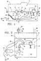
- Apparatus 2 includes a high pressure pump 5 that is adapted to be driven by an electric motor 7 through a shaft 9.
- Pump 5 includes an inlet port 11, connected to an inlet line 13 carrying a first connector 15, and an outlet port 17 connected to a liquid passage 19.
- passage 19 leads to a unit that is adapted to retain a liquid delivered into passage 19 by pump 5 until the temperature and pressure of the liquid are raised desired amounts.
- this retaining unit is constituted by a pressure relief valve 22 which is fluidly connected to an output line 27 having a second connector 29, however, other types of valving arrangements including needle valve, orifices or other types of flow restricting valves, as well as other types of units that would perform the desired retaining function such as a fluid motor, could also be utilized. Since the particular structure of pressure relief valve 22 is known in the art, it will not be detailed herein.
- valve 22 will prevent a liquid drawn through pump 5 into passage 19 from exiting passage 19 until the liquid has been heated by frictional forces acting on the liquid by means the operation of pump 5 and the presence of valve 22.
- Valve 22 is pre-set to a predetermined relief pressure or flow restricting degree depending on the particular use of apparatus 2 and the specific liquid utilized therewith.
- the apparatus 2 of Figure 1 is particularly adapted for use as an in-line water heater, either as a portable unit wherein first and second connectors 15 and 29 are adapted to be readily connected to standard garden hoses or as a home hot water supplying arrangement.
- the water connected to inlet line 13 will typically be at approximately 20 psi (138kPa) and about 50°F (10C). Knowing these parameters and the desired output temperature of the liquid will enable the size of pump 5 and the preset pressure relief level to be selected.
- pump 5 will operate at a rate corresponding to pumping approximately 8 gallons per minute and valve 22 is set at approximately 1500 psi (10340kPa) and will allow a continuous output flow of heated water at the rate of approximately 2 gallons per minute at 20 psi (138kPa).
- valve 22 is set at approximately 1500 psi (10340kPa) and will allow a continuous output flow of heated water at the rate of approximately 2 gallons per minute at 20 psi (138kPa).
- these test numbers are presented for exemplary purposes only and the actual pumping rate, the set pressure relief level, output temperature and output flow rate can be readily determined experimentally.
- a check valve 31 which prevents back pressure on pump 5, particularly after motor 7 de-activated, so as to unload the pump 5 and motor 7.
- one or more sensors 34-36 is provided and signal, through respective lines 38-40, a relay switching unit 42 for controlling the de-activation of motor 7.
- relay switching unit 42 is connected through an electrical line 44 to an ON/OFF switch 45 that is also connected to a power cord 47 having a plug 48.
- the entire heater structure can be located within a portable housing 50.
- sensors 34-36 are provided for safety reasons and, more specifically, to prevent the possibility of the liquid from being heated or pressurized to a dangerous level due to a potential malfunction of one of the components of heating apparatus 2.
- sensor 34 constitutes a pressure sensor
- sensor 35 constitutes a temperature sensor
- sensor 36 constitutes a temperature sensor.
- various types of sensors can be utilized and only one such sensor need be provided, preferably either pressure sensor 34 or temperature sensor 35, for safety reasons, with other sensors merely providing an added level of safety.
- the heating apparatus 2 of Figure 1 has been found to continuously provide a supply of heated water with a greatly reduced power consumption rate over known hot water heaters.
- heating apparatus 2 is extremely compact and lightweight so that it is readily portable.
- FIGS. 2-8 illustrate other arrangements and various preferred embodiments for heating apparatus 2 as will be discussed below. Since the heating apparatus 2 can be used in many environments with little or no change in its structure or function, like reference numerals will be used to represent corresponding structure to that described above and therefore this corresponding structure will not be reiterated.
- FIG. 2 illustrates an arrangement of heating apparatus 2 used in a boiler for generating a supply of steam.
- a tank 53 defines a closed chamber that is filled with a liquid medium to a level 56 so as to define a reservoir 58.
- the apparatus 2 functions as described above to heat the liquid to a predetermined temperature that is greater than the boiling point of water and measured by a thermo-sensor 61 which sends a signal to relay switching unit 42 to de-activate motor 7 when this temperature is reached in reservoir 58.
- a water inlet line 64 extends into tank 53 through an inlet port 65 and a one-way check valve 66.
- a steam outlet line 69 extends from an outlet port 70 of tank 53.
- the liquid medium that is heated constitutes water, however, it is easily possible to utilize other liquids such as hydraulic fluid or an ammonia based liquid and to simply arranged this heated liquid in heat exchange relationship with the incoming water entering tank 53 through inlet line 64 in order to generate the desired steam.
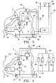
- FIG. 3 illustrates an arrangement wherein the heating apparatus 2 is used as the heat source for a conventional hot water heater.
- a reservoir 76 of fluid preferably hydraulic fluid, is provided through which pump 5 draws the liquid medium to be heated.
- liquid passage 19 is fluidly connected to a liquid conduit 78 that leads to a heat exchanger 82.
- Heat exchanger 82 also has associated therewith a return conduit 85 that leads back to the reservoir 76.
- located in liquid conduit 78 is an solenoid valve 88 which is connected to a thermocouple 90 located in reservoir 76 through a signal line 91.
- Heat exchanger 82 is positioned in a hot water tank 93 and is therefore in heat exchange relationship with water placed in the hot water tank 93.
- a temperature sensor 95 is also positioned in hot water tank 93 and is connected through a line 96 to relay switching unit 42.
- the water for hot water tank 93 is provided via an inlet line 98 and the flow of water from hot water tank 93 is taken through outlet line 99. Also shown at 100 is a pressure relief for the hot water tank 93.
- thermocouple 90 will sense the temperature of the liquid medium in reservoir 76.
- thermocouple 90 If the temperature signaled by thermocouple 90 is above a prescribed limit needed to sufficiently heat the water in tank 93 (generally in the order of 71C (160°F)), solenoid valve 88 will open liquid conduit 78 and the pumped liquid medium will flow to the heat exchanger 82 to heat the water in tank 93 as desired. Preferably, a fraction of the pumped liquid will still flow through liquid passage 19 to be further heated as well.
- solenoid valve 88 will remain closed and all the liquid pumped will have to flow through liquid passage 19 and therefore will be heated in the manner described above. This recirculation process will then continue until the temperature in the reservoir 76 is high enough to open solenoid valve 88. If the temperature in reservoir gets dangerously high as sensed by thermosensor 61, motor 7 will be de-activated as described above with respect to the Figure 2 arrangement. In addition, sensors 34 and 35 are shown here, while sensor 36 has not been shown for simplicity of the drawing.
- the arrangement of Figure 4 represents utilizing the heating apparatus 2 in a radiant heating system.
- the heating apparatus 2 is arranged and works essentially the same in this arrangement as that described above with respect to the Figure 3 arrangement, except as mentioned below.
- Liquid conduit 78 flows into a branch line 103 that lead through sub-conduits (not labeled) to a plurality of radiant heat exchangers 105-108 arranged in parallel. Each heat exchanger 105-108 leads to a common return line 110 to deliver the liquid medium back to the reservoir 76.
- no corresponding temperature sensor to sensor 95 is utilized here. Instead, motor 7 is controlled during normal operation depending on the setting of a thermostat such as that indicated at 112 which, of course, still senses an operating parameter which is, at least indirectly, related to the raised pressure and/or temperature of the liquid medium.
- FIG. 5 The embodiment of Figure 5 is presented to illustrate the use of heating apparatus 2 in a pool, spa or the like water heating environment.
- heating apparatus 2 essentially works in the same manner as that described above, but located downstream of solenoid valve 88 and before heat exchanger 82 is a fluid motor 117.
- motor 117 constitutes an hydraulic motor of preferably fixed displacement. Fluid motor 117 is driven when the liquid medium is sent through liquid conduit 78 upon the opening of valve 88.
- thermostat 112 is adjusted to set a desired water temperature for the pool, spa or the like.
- Fluid motor 117 is drivingly connected to a water pump 120 having an associated inlet line 121 and a water outlet line 123 with the water outlet line 123 being in heat transfer relationship with heat exchanger 82 for heating of the water flowing therethrough.
- a water pump 120 having an associated inlet line 121 and a water outlet line 123 with the water outlet line 123 being in heat transfer relationship with heat exchanger 82 for heating of the water flowing therethrough.
- liquid conduit 78 is provided with an anti-cavitation device in the form of a check valve 127 which opens the inlet to fluid motor 117 to either atmosphere (as shown) or reservoir 76 when there is no pressure in the line due to the closing of solenoid valve 88.
- thermostat 112 could operate on a timer basis without affecting the overall operation of the invention and solenoid valve 08 could be opened, either fully or partially, and motor 7 could be readily controlled to operate in a non-heating mode to simply circulate the pool water, such as by providing a valve at the juncture of liquid passage 19 and liquid conduit 78 to prevent flow through passage 19 or by providing a valve which would enable the flow through water outlet line 123 to bypass heat exchanger 82.
- FIG. 6 The embodiment of Figure 6 is almost identical to the embodiment described above with reference to Figure 5 except that fluid motor 117 drives a blower 139 that directs a flow of air over heat exchanger 82 such that a forced air heating system is provided.
- fluid motor 117 drives a blower 139 that directs a flow of air over heat exchanger 82 such that a forced air heating system is provided.
- a conventional forced air heating system incorporating a resistance heating element can be replaced in accordance with the present invention and operated at well below, i.e. approximately half, the cost associated with operating the conventional system. Again, this arrangement could also readily be used for simply driving blower 139 in a fan or air circulating mode.
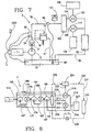
- Figure 7 illustrates the heating apparatus 2 of a preferred embodiment incorporated in a clothes dryer.
- a flow divider 152 is provided in liquid conduit 78 downstream of solenoid valve 88 to divide liquid conduit 78 into sub-conduits 154 and 155.
- Sub-conduit 154 leads to a second fluid motor 157 which is adapted to drive a rotary drum 158 of the clothes dryer.
- Sub-conduit 155 leads to a fluid motor 117 which drives blower 139.
- Blower 139 functions in this embodiment to direct a flow of heated air into rotary drum 158 commensurate with the operation of known clothes drying units.
- the thermostat of the above-described embodiments is replaced with a timer unit 160 provided on a conventional clothes dryer control panel.
- the operation of the heating apparatus 2 in accordance with this embodiment is the same as that described above given the like reference numerals which refer to corresponding parts in the embodiments and therefore the operation will not be further described here.
- motor 7 directly drives a first pump 172 through a first shaft 173.
- first pump 172 provides a flow of fluid to drive a first motor 175 through a first line 177 and first motor 175 has an output shaft 179 which drives a second pump 181.
- Second pump 181 is interconnected through a second line 183 to a second motor 185 which has associated therewith a third output shaft 187 that drives a third pump 189.
- Third pump 189 has an output that leads into a passage 192.
- each of first, second and third pumps 172, 181 and 189, as well as first and second motors 175 and 185, are submerged within a reservoir 195 into which fluid, preferably hydraulic fluid, can be filled at fill port 196 which also preferably functions to vent reservoir 195.
- first pump 172 can draw fluid from within reservoir 195 and the output is delivered to passage 192. Since these various components are submerged within reservoir 195, the heat generated by the operation of these components merely advantageously adds to the heating of the fluid within reservoir 195.
- this arrangement is shown in the embodiment of Figure 5, it should be readily understood that such a multiple pump and motor drive combination that is submerged within a reservoir can be readily incorporated in the various embodiments described above, particularly the embodiment of Figure 6.
- Figure 8 does not include a bypass loop similar to that in the embodiments described above which can be used for initial preheating of the fluid medium. Therefore, Figure 8 exemplifies that such a preheating bypass loop is not mandatory in connection with the present invention but the actual operation of the unit can progressively heat the fluid in the reservoir.
- a heating element electric or otherwise as generically indicated at 197, could be provided within reservoir 195 to preheat the fluid or to maintain the fluid in reservoir 195 at a minimal desired temperature. Heating element 197, although not particularly illustrated in this Figure, could be connected to a temperature relay for automatically controlling this desired fluid temperature.
- passage 192 includes a first branch line 201 leading to a first drive motor 204 that is connected to a blower 207 through a first driveshaft 210.
- First drive motor 204 is also connected to a first return line 213 that dumps fluid, reduced in pressure and increased in temperature, back to reservoir 195.
- Passage 192 also has associated therewith a second branch line 216 that leads to a second drive motor 218.
- second drive motor 218 is connected to a compressor 221 through a second driveshaft 223 and has associated therewith a second return line 224 leading to reservoir 195.
- Compressor 221 forms part of a circuit generally indicated at 226 that also includes first and second heat exchangers 229 and 232.
- heat exchanger 229 actually constitutes an evaporator that is submerged within the fluid of reservoir 195 and heat exchanger 232 constitutes a condenser.
- Evaporator 229 is connected to compressor 221 through a first flow line 235, compressor 221 is fluidly connected to condenser 232 by a second flow line 237 and condenser 232 is connected to evaporator 229 through a third flow line 239.
- circuit 226 illustrates a general circuit associated with a heat pump.
- evaporator 229 will receive heat from the fluid within the reservoir 195.
- the arrangement of Figure 8 attempts to simulate a geothermal heat pump system in that the fluid medium within reservoir 195 is not adversely affected by ambient atmosphere such that this system does not have the associate disadvantages of current heat pumps but rather can be used in much colder environments.
- first and second drive motors 204 and 218 will perform a retaining function similar to that of pressure relief valve 22, especially considering the back pressure that is generated due to the presence of drive blower 207 and compressor 221. Therefore, passage 192 and first and second branch lines 201 and 216 will have associated fluid pressures greater than at least fifteen times the pressure within the reservoir 195 in order to generate a sufficient amount of heat.
- operation of first and second drive motors 204 and 218, which are needed to heat the fluid medium in reservoir 195 also perform mechanical work by driving blower 207 and compressor 221 and therefore operating circuit 226. With blower 207 being arranged adjacent condenser 232, the generated air flow will be heated and then can be directed to a desired zone, such as throughout a residential house, for heating purposes.
- the heating apparatus 2 of the present invention is versatile and can readily supply a heated fluid which can be used for various purposes either directly or as a medium for heating another fluid.
- supplemental fluid motors could be readily incorporated to drive other auxiliary components such as, for example, a generator, an exhaust fan or the like.
- the heating apparatus is extremely compact and energy efficient.
Landscapes
- Engineering & Computer Science (AREA)
- Physics & Mathematics (AREA)
- Thermal Sciences (AREA)
- Chemical & Material Sciences (AREA)
- Combustion & Propulsion (AREA)
- Mechanical Engineering (AREA)
- General Engineering & Computer Science (AREA)
- Steam Or Hot-Water Central Heating Systems (AREA)
- Physical Or Chemical Processes And Apparatus (AREA)
- General Induction Heating (AREA)
Claims (13)
- Vorrichtung (2) zum Erwärmen eines flüssigen Mediums, umfassend:einen Vorrat (76);einen Flüssigkeitskanal (19) in Fließverbindung mit dem Vorrat (76);Mittel (5) zum Abziehen eines flüssigen Mediums aus dem Vorrat (76) in den Flüssigkeitskanal (19) bei einem ersten Druck und einer ersten Temperatur,Mittel zum Halten des flüssigen Mediums in dem Flüssigkeitskanal (19), bis das flüssige Medium auf einen zweiten Druck gebracht ist, der ein Mehrfaches höher ist als der erste Druck, und durch Reibung auf eine zweite Temperatur aufgeheizt ist, die größer ist als die erste Temperatur;Mittel zum Freisetzen des flüssigen Mediums in einem erwärmten Zustand aus dem Flüssigkeitskanal (19) bei einem dritten Druck, der niedriger ist als der zweite Druck;eine Flüssigkeitsleitung (78), die eingerichtet ist zum Aufnehmen eines Flusses des flüssigen Mediums;einen Flüssigkeitsmotor (117), der in Fließverbindung mit der Flüssigkeitsleitung (78) angeordnet ist;einen Wärmetauscher (82) mit einem Einlass in Fließverbindung mit der Flüssigkeitsleitung (78) und mit einem Auslass, der zum Vorrat (76) führt, wobei der Wärmetauscher (82) dazu eingerichtet ist, durch das flüssige Medium erwärmt zu werden;Mittel (34, 35, 61) zum Bestimmen einer Betriebsgröße des flüssigen Mediums; undMittel (42) zum automatischen Steuern des Betriebs der Abziehmittel auf Grundlage der bestimmten Betriebsgröße.
- Vorrichtung nach Anspruch 1, wobei jedes der Haltemittel und der Freisetzungsmittel umfasst, zumindest teilweise: einen Abschnitt eines Druckreduzierventils (22), angeordnet in dem Flüssigkeitskanal (19) stromabwärts von den Abziehmitteln (5).
- Vorrichtung nach Anspruch 1, wobei die Vorrichtung eingerichtet ist zum Entwickeln eines zweiten Drucks im Bereich von 2068 kPa (300 psi) bis 20684 kPa (3000 psi).
- Vorrichtung nach Anspruch 1, wobei die Vorrichtung eingerichtet ist zum Entwickeln der zweiten Temperatur in einem Bereich von -6,7°C (20°F) bis 104°C (220°F).
- Vorrichtung nach Anspruch 1, wobei das Freisetzmittel das flüssige Medium zurück in den Vorrat (76) abführt.
- Vorrichtung nach Anspruch 1, wobei die Flüssigkeitsleitung (78) mit dem Flüssigkeitskanal (19) verbunden ist zwischen den Abziehmitteln und den Freisetzmitteln, und wobei die Vorrichtung ferner umfasst: Mittel zum Steuern des Flusses des flüssigen Mediums zu der Flüssigkeitsleitung (78), wobei die Mittel zum Steuern des Flusses des flüssigen Mediums zu der Flüssigkeitsleitung (78) zumindest ein Ventil (88) umfassen, das in der Flüssigkeitsleitung angeordnet ist.
- Vorrichtung nach Anspruch 1, ferner umfassend: ein Pumpmittel (120) in Antriebsverbindung mit dem ersten Flüssigkeitsmotor (117), zum Abziehen eines Flusses von Wasser und Pumpen des Wassers in eine Wärmeaustauschbeziehung mit dem ersten Wärmetauscher (82).
- Vorrichtung nach Anspruch 1, ferner umfassend eine Luftgebläseeinheit (139) in Antriebsverbindung mit dem Flüssigkeitsmotor (117), um einen Luftstrom in Richtung auf den Wärmetauscher (82) zu erzeugen.
- Vorrichtung nach Anspruch 1, ferner umfassend:Mittel (152) zum Teilen der Flüssigkeitsleitung in erste (154) und zweite (155) Unter-Leitungen; undeinen weiteren Flüssigkeitsmotor (157), wobei der Flüssigkeitsmotor (117) und der weitere Flüssigkeitsmotor (157) in Fließverbindung eingerichtet sind mit der ersten (154) bzw. zweiten (155) Unter-Leitung, so dass die Flüssigkeitsmotoren (117, 157) angetrieben werden, wenn das flüssige Medium durch die ersten (154) und zweiten (155) Unter-Leitungen fließt.
- Vorrichtung nach Anspruch 9, ferner gleichzeitig umfassend: eine Rotationstrommel (158), die in Antriebsverbindung mit dem Flüssigkeitsmotor (117) und einer Gebläseeinheit (139) steht, die in Antriebsverbindung steht mit dem weiteren Flüssigkeitsmotor (157), wobei die Gebläseeinheit (139) eingerichtet ist zum Hervorrufen eines Luftstroms in Richtung auf die Trommel (158), während sie in Wärmeaustauschbeziehung mit dem ersten Wärmetauscher (82) steht.
- Verfahren zum Erwärmen eines flüssigen Mediums, umfassend:Abziehen eines flüssigen Mediums aus einem Vorrat (76);Abgeben des flüssigen Mediums in eine Flüssigkeitsleitung (78) bei einem ersten Druck und einer ersten Temperatur;Bringen des flüssigen Mediums in der Flüssigkeitsleitung (78) auf einen um ein Mehrfaches höheren Druck als den ersten Druck, während das flüssige Medium durch Reibung auf eine zweite Temperatur erwärmt wird, die größer ist als die erste Temperatur;Ausgeben des flüssigen Mediums, in einem erwärmten Zustand, bei einem Druck innerhalb des fünffachen des ersten Drucks;Antreiben eines Flüssigkeitsmotors (117) durch das flüssige Medium;Übertragen von Wärme von dem flüssigen Medium auf einen Wärmetauscher (82);Rückführen des flüssigen Mediums in den Vorrat (76);Bestimmen einer Betriebsgröße des flüssigen Mediums; undSteuern der Abgabe des flüssigen Mediums in die Flüssigkeitsleitung (78) in Abhängigkeit von der bestimmten Betriebsgröße.
- Verfahren nach Anspruch 11, ferner umfassend:Antreiben einer Gebläseeinheit (139) durch den Flüssigkeitsmotor (117); undRichten eines Luftstroms, der durch den Betrieb der Gebläseeinheit (139) hervorgerufen wird, in eine Wärmeaustauschbeziehung mit dem Wärmetauscher (82).
- Verfahren nach Anspruch 11, ferner umfassend:Abziehen des flüssigen Mediums aus dem Vorrat (76) durch eine motorgetriebene Pumpe (5);Feststellen wann die bestimmte Betriebsgröße erreicht ist; undDeaktivieren der motorgetriebenen Pumpe (5).
Applications Claiming Priority (3)
| Application Number | Priority Date | Filing Date | Title |
|---|---|---|---|
| US538339 | 1995-10-03 | ||
| US08/538,339 US5709201A (en) | 1995-10-03 | 1995-10-03 | Method and apparatus for heating a liquid medium |
| PCT/US1996/015157 WO1997013103A1 (en) | 1995-10-03 | 1996-09-30 | Method and apparatus for heating a liquid medium |
Publications (3)
| Publication Number | Publication Date |
|---|---|
| EP0853746A1 EP0853746A1 (de) | 1998-07-22 |
| EP0853746A4 EP0853746A4 (de) | 1998-12-23 |
| EP0853746B1 true EP0853746B1 (de) | 2005-07-20 |
Family
ID=24146511
Family Applications (1)
| Application Number | Title | Priority Date | Filing Date |
|---|---|---|---|
| EP96933847A Expired - Lifetime EP0853746B1 (de) | 1995-10-03 | 1996-09-30 | Vorrichtung und verfahren zur erwärmung eines flüssigen mediums |
Country Status (7)
| Country | Link |
|---|---|
| US (2) | US5709201A (de) |
| EP (1) | EP0853746B1 (de) |
| JP (1) | JPH11512813A (de) |
| AT (1) | ATE300019T1 (de) |
| AU (1) | AU715990B2 (de) |
| DE (1) | DE69634958T2 (de) |
| WO (1) | WO1997013103A1 (de) |
Families Citing this family (26)
| Publication number | Priority date | Publication date | Assignee | Title |
|---|---|---|---|---|
| US6154978A (en) * | 1999-05-05 | 2000-12-05 | American Dryer Corporation | Apparatus and method for confirming initial conditions of clothes drying equipment prior to start of drying cycle |
| US6596178B1 (en) * | 2001-12-18 | 2003-07-22 | Hydro Development Llc | Fluid purification system |
| EP1541811A3 (de) * | 2003-09-18 | 2005-06-22 | Matsushita Electric Industrial Co., Ltd. | Wärme-Kraft Kopplungssystem |
| US20050184167A1 (en) * | 2004-02-24 | 2005-08-25 | Stanley Bach | Heating, ventilating, and air-conditioning system utilizing a pressurized liquid and a fluid-turbine generator |
| KR100624815B1 (ko) * | 2004-08-17 | 2006-09-20 | 엘지전자 주식회사 | 코제너레이션 시스템의 배기가스 열교환기 |
| KR100579576B1 (ko) * | 2004-08-17 | 2006-05-15 | 엘지전자 주식회사 | 열병합 발전 시스템 |
| US7523873B1 (en) * | 2004-11-04 | 2009-04-28 | Lopes Walter R | Heating system |
| WO2006101360A1 (en) * | 2005-03-25 | 2006-09-28 | Lg Electronics Inc. | Laundry machine |
| DE102007007354B4 (de) * | 2006-02-20 | 2013-10-10 | Lg Electronics Inc. | Wäschetrockner und Verfahren zur Steuerung |
| US7451753B2 (en) * | 2006-04-21 | 2008-11-18 | Pratt & Whitney Canada Corp. | Pre-heating of a liquid in an aircraft reservoir |
| US20070246302A1 (en) * | 2006-04-21 | 2007-10-25 | Pratt & Whitney Canada Corp. | Pre-heating an aircraft oil reservoir |
| KR100830514B1 (ko) * | 2006-06-12 | 2008-05-21 | 엘지전자 주식회사 | 건조기 및 그 제어방법 |
| US7997006B2 (en) * | 2007-01-12 | 2011-08-16 | Lg Electronics Inc. | Laundry machine and control method thereof |
| US8275516B2 (en) * | 2009-07-21 | 2012-09-25 | Trimble Navigation Limited | Agricultural vehicle autopilot rollover risk assessment system |
| US20120205075A1 (en) * | 2011-02-16 | 2012-08-16 | Labadini Richard D | Heating system |
| DE102011106177B4 (de) * | 2011-06-30 | 2021-11-25 | Airbus Operations Gmbh | Temperaturregelung eines Zirkulationsfluidsystems durch thermo-optimierten Betrieb einer Zirkulationspumpe |
| US9109806B2 (en) * | 2011-08-19 | 2015-08-18 | Tai-Her Yang | Heating/cooling system that utilizes secondary fluid pumped through a heat exchanger by the pressure of a thermal exchange fluid |
| US9228760B2 (en) | 2012-04-27 | 2016-01-05 | Mac, Inc. | Flameless heating system |
| GB2503512B (en) * | 2012-06-29 | 2016-06-01 | Ford Global Tech Llc | Apparatus and method for heating engine oil in a pump by use of friction |
| US9982585B2 (en) * | 2013-03-15 | 2018-05-29 | Conleymax Inc. | Flameless fluid heater |
| US10495025B2 (en) | 2013-03-15 | 2019-12-03 | Conleymax Inc. | Flameless combo heater |
| US10408548B2 (en) | 2013-09-25 | 2019-09-10 | Conleymax Inc. | Flameless glycol heater |
| US10145586B2 (en) | 2015-01-20 | 2018-12-04 | Wacker Neuson Production Americas Llc | Flameless heater |
| CA3207446A1 (en) * | 2022-07-29 | 2024-01-29 | Stewart & Stevenson Llc | Adaptable inline fluid heating system |
| CN116624270B (zh) * | 2023-04-03 | 2026-04-10 | 中国航发湖南动力机械研究所 | 一种滑油加温装置 |
| DE102024118226A1 (de) * | 2024-06-27 | 2025-12-31 | Liebherr-Werk Telfs Gmbh | Mobile Arbeitsmaschine |
Citations (1)
| Publication number | Priority date | Publication date | Assignee | Title |
|---|---|---|---|---|
| EP0543606A1 (de) * | 1991-11-18 | 1993-05-26 | Sanden Corporation | Verfahren und Vorrichtung für die Klimaanlage eines Fahrzeug |
Family Cites Families (13)
| Publication number | Priority date | Publication date | Assignee | Title |
|---|---|---|---|---|
| US3791167A (en) * | 1972-01-20 | 1974-02-12 | M Eskeli | Heating and cooling wheel with dual rotor |
| US4060194A (en) * | 1976-03-08 | 1977-11-29 | Lutz George H | Heating system and element therefor |
| DE2750894A1 (de) * | 1977-09-14 | 1979-03-15 | Elmapa Nv | Einrichtung zur erzeugung von waermeenergie und elektrischer energie |
| DE2932448A1 (de) * | 1979-08-10 | 1981-02-26 | Kloeckner Humboldt Deutz Ag | Einrichtung zum beheizen der bedienungskabine einer von einer brennkraftmaschine angetriebenen maschine |
| DE2940643A1 (de) * | 1979-10-06 | 1981-04-16 | Klöckner-Humboldt-Deutz AG, 5000 Köln | Einrichtung zum an- bzw. aufheizen von maschinen |
| DE3012760A1 (de) * | 1980-04-02 | 1981-10-08 | Klöckner-Humboldt-Deutz AG, 5000 Köln | Fluessigkeitsheizungssystem |
| US4357931A (en) * | 1980-09-11 | 1982-11-09 | Wolpert Kenneth R | Flameless heat source |
| DE3123633A1 (de) * | 1981-06-15 | 1982-12-30 | Klöckner-Humboldt-Deutz AG, 5000 Köln | Heizungssystem mit schmieroeldrosselung fuer kraftfahrzeuge |
| FI832133L (fi) * | 1982-06-17 | 1983-12-18 | Etienne Vandervelden | Anordning foer att producera vaermeenergi fraon en vaederkvarn eller vindturbin |
| US4685443A (en) * | 1986-05-12 | 1987-08-11 | Lloyd S. Myster | Hydraulic friction heat generator |
| US4926904A (en) * | 1988-08-08 | 1990-05-22 | Power Flo Products Corp. | Pressure washer |
| US5385298A (en) * | 1991-04-08 | 1995-01-31 | Hydro Dynamics, Inc. | Apparatus for heating fluids |
| US5188090A (en) * | 1991-04-08 | 1993-02-23 | Hydro Dynamics, Inc. | Apparatus for heating fluids |
-
1995
- 1995-10-03 US US08/538,339 patent/US5709201A/en not_active Expired - Lifetime
-
1996
- 1996-09-30 AT AT96933847T patent/ATE300019T1/de not_active IP Right Cessation
- 1996-09-30 JP JP9514291A patent/JPH11512813A/ja active Pending
- 1996-09-30 AU AU72422/96A patent/AU715990B2/en not_active Ceased
- 1996-09-30 US US09/044,000 patent/US5979435A/en not_active Expired - Lifetime
- 1996-09-30 EP EP96933847A patent/EP0853746B1/de not_active Expired - Lifetime
- 1996-09-30 DE DE69634958T patent/DE69634958T2/de not_active Expired - Lifetime
- 1996-09-30 WO PCT/US1996/015157 patent/WO1997013103A1/en not_active Ceased
Patent Citations (1)
| Publication number | Priority date | Publication date | Assignee | Title |
|---|---|---|---|---|
| EP0543606A1 (de) * | 1991-11-18 | 1993-05-26 | Sanden Corporation | Verfahren und Vorrichtung für die Klimaanlage eines Fahrzeug |
Also Published As
| Publication number | Publication date |
|---|---|
| DE69634958T2 (de) | 2006-03-30 |
| AU715990B2 (en) | 2000-02-17 |
| US5979435A (en) | 1999-11-09 |
| EP0853746A1 (de) | 1998-07-22 |
| EP0853746A4 (de) | 1998-12-23 |
| US5709201A (en) | 1998-01-20 |
| WO1997013103A1 (en) | 1997-04-10 |
| JPH11512813A (ja) | 1999-11-02 |
| ATE300019T1 (de) | 2005-08-15 |
| AU7242296A (en) | 1997-04-28 |
| DE69634958D1 (de) | 2005-08-25 |
Similar Documents
| Publication | Publication Date | Title |
|---|---|---|
| US5979435A (en) | Method and apparatus for heating a liquid medium | |
| AU2007240230B2 (en) | Pumpless combination instantaneous/storage water heater system | |
| US8511296B2 (en) | Solar heating systems | |
| US20080216821A1 (en) | Solar heating systems with integrated circulator control | |
| US4153199A (en) | Fireplace heating system | |
| US2948277A (en) | Two temperature water heating system | |
| WO1999031441A1 (en) | Venturi apparatus for flow control | |
| CA2233471C (en) | Method and apparatus for heating a liquid medium | |
| JPH06509636A (ja) | 燃料燃焼式ヒートポンプ装置 | |
| US20040134649A1 (en) | Carpet cleaning system | |
| KR20190010972A (ko) | 난방 및 온수 겸용 보일러 시스템 | |
| JP4031484B2 (ja) | 複合熱源機 | |
| US20060032844A1 (en) | Vehicle coolant heating system | |
| US20050184167A1 (en) | Heating, ventilating, and air-conditioning system utilizing a pressurized liquid and a fluid-turbine generator | |
| AU763394B2 (en) | Hot water system | |
| KR930010393B1 (ko) | 급탕기의 유량제어방법 | |
| JPH03186151A (ja) | 大能力給湯装置 | |
| GB2200733A (en) | Instantaneous water heaters for showers | |
| JP3172015B2 (ja) | 自動風呂装置及び該装置における湯水の加熱方法 | |
| RU2153131C1 (ru) | Устройство для нагрева жидкостей | |
| CN214949782U (zh) | 燃气热水器 | |
| JP3342158B2 (ja) | 冷媒循環式空調システム | |
| TR2021010747U5 (tr) | Eşzamanli isitma ve sicak su sağlayan kombi̇ | |
| US382383A (en) | Buildings | |
| WO1991003688A1 (en) | A pump module |
Legal Events
| Date | Code | Title | Description |
|---|---|---|---|
| PUAI | Public reference made under article 153(3) epc to a published international application that has entered the european phase |
Free format text: ORIGINAL CODE: 0009012 |
|
| 17P | Request for examination filed |
Effective date: 19980501 |
|
| AK | Designated contracting states |
Kind code of ref document: A1 Designated state(s): AT BE CH DE ES FR GB IT LI NL SE |
|
| A4 | Supplementary search report drawn up and despatched |
Effective date: 19981105 |
|
| AK | Designated contracting states |
Kind code of ref document: A4 Designated state(s): AT BE CH DE ES FR GB IT LI NL SE |
|
| 17Q | First examination report despatched |
Effective date: 20010816 |
|
| GRAP | Despatch of communication of intention to grant a patent |
Free format text: ORIGINAL CODE: EPIDOSNIGR1 |
|
| GRAS | Grant fee paid |
Free format text: ORIGINAL CODE: EPIDOSNIGR3 |
|
| GRAA | (expected) grant |
Free format text: ORIGINAL CODE: 0009210 |
|
| AK | Designated contracting states |
Kind code of ref document: B1 Designated state(s): AT BE CH DE ES FR GB IT LI NL SE |
|
| PG25 | Lapsed in a contracting state [announced via postgrant information from national office to epo] |
Ref country code: NL Free format text: LAPSE BECAUSE OF FAILURE TO SUBMIT A TRANSLATION OF THE DESCRIPTION OR TO PAY THE FEE WITHIN THE PRESCRIBED TIME-LIMIT Effective date: 20050720 Ref country code: LI Free format text: LAPSE BECAUSE OF FAILURE TO SUBMIT A TRANSLATION OF THE DESCRIPTION OR TO PAY THE FEE WITHIN THE PRESCRIBED TIME-LIMIT Effective date: 20050720 Ref country code: IT Free format text: LAPSE BECAUSE OF FAILURE TO SUBMIT A TRANSLATION OF THE DESCRIPTION OR TO PAY THE FEE WITHIN THE PRESCRIBED TIME-LIMIT;WARNING: LAPSES OF ITALIAN PATENTS WITH EFFECTIVE DATE BEFORE 2007 MAY HAVE OCCURRED AT ANY TIME BEFORE 2007. THE CORRECT EFFECTIVE DATE MAY BE DIFFERENT FROM THE ONE RECORDED. Effective date: 20050720 Ref country code: CH Free format text: LAPSE BECAUSE OF FAILURE TO SUBMIT A TRANSLATION OF THE DESCRIPTION OR TO PAY THE FEE WITHIN THE PRESCRIBED TIME-LIMIT Effective date: 20050720 Ref country code: BE Free format text: LAPSE BECAUSE OF FAILURE TO SUBMIT A TRANSLATION OF THE DESCRIPTION OR TO PAY THE FEE WITHIN THE PRESCRIBED TIME-LIMIT Effective date: 20050720 Ref country code: AT Free format text: LAPSE BECAUSE OF FAILURE TO SUBMIT A TRANSLATION OF THE DESCRIPTION OR TO PAY THE FEE WITHIN THE PRESCRIBED TIME-LIMIT Effective date: 20050720 |
|
| REG | Reference to a national code |
Ref country code: GB Ref legal event code: FG4D |
|
| REG | Reference to a national code |
Ref country code: CH Ref legal event code: EP |
|
| REF | Corresponds to: |
Ref document number: 69634958 Country of ref document: DE Date of ref document: 20050825 Kind code of ref document: P |
|
| PG25 | Lapsed in a contracting state [announced via postgrant information from national office to epo] |
Ref country code: SE Free format text: LAPSE BECAUSE OF FAILURE TO SUBMIT A TRANSLATION OF THE DESCRIPTION OR TO PAY THE FEE WITHIN THE PRESCRIBED TIME-LIMIT Effective date: 20051020 |
|
| PG25 | Lapsed in a contracting state [announced via postgrant information from national office to epo] |
Ref country code: ES Free format text: LAPSE BECAUSE OF FAILURE TO SUBMIT A TRANSLATION OF THE DESCRIPTION OR TO PAY THE FEE WITHIN THE PRESCRIBED TIME-LIMIT Effective date: 20051031 |
|
| REG | Reference to a national code |
Ref country code: CH Ref legal event code: PL |
|
| NLV1 | Nl: lapsed or annulled due to failure to fulfill the requirements of art. 29p and 29m of the patents act | ||
| ET | Fr: translation filed | ||
| PLBE | No opposition filed within time limit |
Free format text: ORIGINAL CODE: 0009261 |
|
| STAA | Information on the status of an ep patent application or granted ep patent |
Free format text: STATUS: NO OPPOSITION FILED WITHIN TIME LIMIT |
|
| 26N | No opposition filed |
Effective date: 20060421 |
|
| PGFP | Annual fee paid to national office [announced via postgrant information from national office to epo] |
Ref country code: GB Payment date: 20120926 Year of fee payment: 17 |
|
| PGFP | Annual fee paid to national office [announced via postgrant information from national office to epo] |
Ref country code: DE Payment date: 20120927 Year of fee payment: 17 Ref country code: FR Payment date: 20120926 Year of fee payment: 17 |
|
| GBPC | Gb: european patent ceased through non-payment of renewal fee |
Effective date: 20130930 |
|
| REG | Reference to a national code |
Ref country code: DE Ref legal event code: R119 Ref document number: 69634958 Country of ref document: DE Effective date: 20140401 |
|
| REG | Reference to a national code |
Ref country code: FR Ref legal event code: ST Effective date: 20140530 |
|
| PG25 | Lapsed in a contracting state [announced via postgrant information from national office to epo] |
Ref country code: GB Free format text: LAPSE BECAUSE OF NON-PAYMENT OF DUE FEES Effective date: 20130930 |
|
| PG25 | Lapsed in a contracting state [announced via postgrant information from national office to epo] |
Ref country code: DE Free format text: LAPSE BECAUSE OF NON-PAYMENT OF DUE FEES Effective date: 20140401 Ref country code: FR Free format text: LAPSE BECAUSE OF NON-PAYMENT OF DUE FEES Effective date: 20130930 |