EP0853773B1 - Vorrichtung zur kühlung eines thermisch entwickelten blattes - Google Patents
Vorrichtung zur kühlung eines thermisch entwickelten blattes Download PDFInfo
- Publication number
- EP0853773B1 EP0853773B1 EP96930804A EP96930804A EP0853773B1 EP 0853773 B1 EP0853773 B1 EP 0853773B1 EP 96930804 A EP96930804 A EP 96930804A EP 96930804 A EP96930804 A EP 96930804A EP 0853773 B1 EP0853773 B1 EP 0853773B1
- Authority
- EP
- European Patent Office
- Prior art keywords
- sheet
- thermally
- region
- insulative material
- thermally insulative
- Prior art date
- Legal status (The legal status is an assumption and is not a legal conclusion. Google has not performed a legal analysis and makes no representation as to the accuracy of the status listed.)
- Expired - Lifetime
Links
Images

Classifications
-
- G—PHYSICS
- G03—PHOTOGRAPHY; CINEMATOGRAPHY; ANALOGOUS TECHNIQUES USING WAVES OTHER THAN OPTICAL WAVES; ELECTROGRAPHY; HOLOGRAPHY
- G03D—APPARATUS FOR PROCESSING EXPOSED PHOTOGRAPHIC MATERIALS; ACCESSORIES THEREFOR
- G03D13/00—Processing apparatus or accessories therefor, not covered by groups G11B3/00 - G11B11/00
- G03D13/002—Heat development apparatus, e.g. Kalvar
Definitions
- the present invention is generally directed to thermal processing technology and, more particularly, to techniques for cooling sheets of thermally-processed material with reduced defects.
- Sheets of thermally-processed material are widely used in a variety of applications.
- various medical, industrial, and graphic imaging applications use sheets of photothermographic materials to produce high-quality images.
- Sheets, as used in this description may refer, for example, to short segments, longer lengths, or continuous rolls of photothermographic material.
- the photothermographic material is photographically exposed to form a latent image.
- a thermal processing apparatus is used to thermally develop the latent image.
- the thermal processing apparatus heats the sheet to at least a threshold temperature for a period of time. Subsequently, the sheet of photothermographic material is cooled by a cooling article associated with the thermal processing apparatus to allow a user to hold the element while examining the developed image.
- the sheet of photothermographic material can be susceptible to defects caused by uneven cooling. The defects may not be uniform across the entire sheet. Rather, such defects may be more pronounced in certain portions of the sheet.
- the trailing portion of the sheet can be more susceptible to processing defects.
- the trailing portion is the final portion of the sheet to exit the processing apparatus. As leading portions of a single sheet exit the thermal processing apparatus, they tend to heat the cooling article.
- the trailing portion of the sheet generally is unsupported and tends to drop downward immediately upon exit from the thermal processing apparatus. The trailing portion immediately contacts the hot cooling article previously heated by the leading portions of the sheet. Thus, the trailing portion of the sheet undergoes a different cooling profile than the leading portions, causing uneven cooling across the sheet. The uneven cooling leads to visible defects such as spots and streaks in the trailing portion.
- the present invention is directed to an article for cooling sheets of thermally-processed material, and to an apparatus for thermally processing a sheet of thermally-processable material, in accordance with claim 1 and claim 10, respectively.
- the cooling article of the present invention includes a plate positioned adjacent the exit of the thermal processor.
- the plate has a surface for receiving a sheet of thermally-processed material such that the sheet of thermally-processed material moves along the surface.
- a first region of the surface of the plate adjacent the exit of the thermal processor includes a thermally insulative material, whereas a second region of the surface of the plate on a side of the first region opposite the exit of the thermal processor includes a thermally conductive material.
- the sheet of thermally-processed material contacts the thermally insulative material during movement in the first region, and contacts the thermally conductive material during movement in the second region.
- the thermally insulative material prevents excessive heating of the first region of the cooling plate by leading portions of the sheet of thermally-processed material.
- the thermally insulative material thereby reduces defects in the trailing portion of the sheet of thermally-processed material due to uneven cooling.
- the reduced defects can contribute, for example, to improved quality in the images produced on sheets of thermally-processed material.
- Fig. 1 is a perspective view of an exemplary cooling article 10, in accordance with the present invention.
- cooling article 10 is positioned adjacent a thermal processing apparatus in the form of a heated drum 12.
- the cooling article 10 receives a sheet 14 of thermally-processed material from heated drum 12.
- the heated drum 12 forms a heating member within the overall thermal-processing apparatus.
- the sheet 14 may comprise, for example, a base 16 coated with a thermally-processable emulsion 18.
- the base 16 may comprise, for example, paper, polyester film, or the like.
- the emulsion 18 may comprise, for example, silver halide-based material, diazo material, or the like.
- the sheet 14 of thermally-processed material is shown in Fig. 1 as a relatively short segment.
- the sheet 14 may be realized by other formats such as, for example, longer lengths or continuous rolls of thermally-processed material.
- the cooling article 10 includes a cooling plate 20 having a top surface 22 along which sheet 14 slides upon movement of the sheet outward from an exit associated with the thermal processing apparatus.
- the cooling plate 20 can be flat and stationary.
- the term stationary generally means that cooling plate 20 does not move while sheet 14 slides along the cooling plate.
- the cooling plate 20 can be made from a thermally conductive material such as aluminum, copper, steel, or the like. The cooling plate 20 withdraws heat from sheet 14 to cool the sheet to a sufficiently low temperature so that a user can pick up the sheet to examine the thermally-processed image.
- cooling plate 20 is shown as contacting emulsion 18, although this is not necessary. Rather, cooling plate 20 could contact base 16.
- sheet 14 is cooled while remaining relatively flat and without being constrained or compressed. The lack of constraint and pressure allows for consistent dimensional changes within the sheet 14 during cooling. As a result, significant wrinkling is avoided.
- top surface 22 of the cooling plate is relatively flat and smooth.
- the top surface 22 is sufficiently textured. The texture slows the cooling rate because top surface 22, at any one instance, contacts only a portion of sheet 14 during movement of the sheet along cooling plate 20. As a result, top surface 22 withdraws heat from sheet 14 at a slower rate than if the top surface had not been textured. This slower cooling rate reduces the curling of the sheet 14 that otherwise can occur with more rapid, uneven cooling.
- the texture may be realized, for example, by an array of pits extending only partially through the thickness of top surface 22 or, alternatively, by an array of holes extending through the entire thickness of the top surface.
- a texture that causes top surface 22 to contact approximately twenty to eighty percent of the portion of sheet 14 sliding over top surface 22 of cooling plate 20 balances the reduction of marring of emulsion 18 with the reduction of the curling of sheet 14.
- a texture that causes top surface 22 to contact approximately forty to seventy percent of the portion of sheet 14 sliding over cooling plate 20 more finely balances the reduction of marring and curling.
- top surface 22 has other beneficial effects. For example, when emulsion 18 is heated, gases can be formed and be released from the emulsion. When emulsion 18 contacts top surface 22, the gases can escape from between the emulsion and the top surface. This is referred to as outgassing. Without outgassing, trapped gases can adversely effect the emulsion surface and the image being developed within emulsion 18.
- the cooling article can include side walls 24, 26.
- a top cover (not shown) also may be provided to form, along with side walls 24, 26, a chute through which sheet 14 can pass.
- the chute prevents sheet 14 from sliding sideways off cooling plate 20 and can direct the sheet to an exit port (not shown).
- the chute can be made sufficiently open with a generally C-shaped top cover so that sheets 14 that stick or jam within the chute can be easily cleared by an operator.
- the openness also prevents the trapping of hot air that could reduce convection within the chute and cause uneven cooling.
- the openness and the absence of moving parts within the chute allows for simpler cleaning of residual emulsion 18 from the chute.
- the side walls 24, 26 and top cover can be made of the same material as cooling plate 20.
- the side walls 24, 26 can be formed, for example, by bending lateral portions of cooling plate 20 upwardly. This eliminates sharp edges on which the ends of the sheet 14 can be scratched.
- the top cover can have the same textured surface and be welded to side walls 24, 26, or joined with an epoxy so that the textured surface faces top surface 22 of the cooling plate 20.
- the cooling article can include one or more cooling fins, if desired.
- the cooling fins can be coupled to cooling plate 20 using, for example, epoxy.
- Trailing portion 28 of sheet 14 can be more susceptible to such defects.
- trailing portion 28 is the final portion of sheet 14 to exit the thermal processing apparatus. As leading portions of a single sheet 14 exit the thermal processing apparatus, they tend to heat portions of cooling plate 20 adjacent the exit. The trailing portion 28 generally is unsupported and tends to drop downward immediately upon exit. The trailing portion 28 would immediately contact the hot portions of cooling plate 20 previously heated by the leading portions of the sheet, leading to visible spots or streaks.
- top surface 22 of cooling plate 20 includes at least a first region 30 and a second region 32.
- the first region 30 of top surface 22 is disposed adjacent the exit of the thermal processor and includes a thermally insulative material.
- the second region 32 of top surface 22 is disposed on a side of first region 30 opposite the exit of the thermal processor and includes a thermally conductive material.
- the sheet 14 of thermally-processed material contacts the thermally insulative material during movement in first region 30 and contacts the thermally conductive material during movement in second region 32.
- the thermally insulative material in first region 30 ensures that trailing portion 28 of sheet 14 is not exposed to excessive heat immediately upon contact with cooling plate 20.
- the thermally insulative material in first region 30 prevents excessive heating of cooling plate 20 in the first region.
- the first region 30 can be realized, for example, by placing a sheet 34 of thermally insulative material over a portion of top surface 22.
- the second region 32 can be realized, for example, by leaving a portion of top surface 22 exposed.
- the sheet 34 of thermally insulative material may, for example, be mounted flat on top surface 22 with an adhesive or mechanical fastening mechanism.
- sheet 34 may have a first end 36 attached to the thermal processing apparatus, with a second end 38 placed over cooling plate 22.
- the first end 36 may be attached, for example, to a stripper 40 positioned on thermal processing drum 12.
- the stripper 40 can be positioned adjacent the exit of heated drum 12 to direct sheet 14 away from the heated drum at an angle.
- the first end 36 can be attached to stripper 40 with a clamp or other fastening mechanism.
- sheet 34 of thermally insulative material can be made to support sheet 14 of thermally-processed material and, in particular, trailing portion 28.
- the portion of sheet 34 proximate to second end 38 serves to thermally insulate sheet 14 from cooling plate 20.
- sheet 14 does not excessively heat cooling plate 20 in first region 30, reducing processing defects such as spots or streaks that otherwise could occur upon immediate contact of trailing portion 28 with the first region.
- second region 32 which then serves to cool the sheet.
- the insulative effect of sheet 34 will depend, for the most part, on the coefficient of thermal conductivity of the material used to form the sheet, the thermal mass of the sheet, and the porosity, if any, of the sheet.
- the coefficient of thermal conductivity of the material will, of course, determine the conductivity per unit mass of the material. Given this coefficient, the thermal mass will determine the overall thermal conductivity.
- the porosity will determine the amount of surface area of sheet 34 that actually contacts top surface 22 of cooling plate 20 and the surface of sheet 14 of thermally-processed material.
- the thermal mass can be determined by adjusting the thickness or length of sheet 34 to achieve a desired insulative effect.
- suitable materials for use in making sheet 34 of the thermally insulative material include, for example, natural felts, synthetic felts, textile-based materials, non-woven materials such as blown micro fiber materials, and lower-friction rubbers with sufficient porosity. Other materials having relatively low coefficients of thermal conductivity may also be found suitable for manufacture of sheet 34. Effective insulative effect can be expected, for example, from a sheet 34 made from materials having a coefficient of thermal conductivity in the range of approximately 0 to 1.44 watts/(meter . Kelvin) (0 to 2.5 BTU/hour . foot . degree Fahrenheit) with a specific heat in the range of approximately 0 to 5.0 kilojoules/(kilogram . Kelvin).
- More effective insulative effect can be expected, for example, from a sheet 34 made from materials having a coefficient of thermal conductivity in the range of approximately 0 to 0.029 watts/(meter . Kelvin) (0 to 0.05 BTU/hour . foot . degree Fahrenheit) with a specific heat in the range of approximately 0 to 1.0 kilojoules/(kilogram . Kelvin).
- the specific heat may be determined, for example, by selection of the thickness and surface area of sheet 34. With a given thickness, a better insulative effect can be achieved with a first region 30 that extends further along top surface 22 of cooling plate 20. However, a longer sheet 34 of thermally insulative material in first region 30 will reduce the length of second region 32. The reduced length of second region 32 can reduce the cooling effect of cooling article 10 and thus the through-put of sheets 14 of thermally-processed material through the cooling article. With a sheet 34 of thermally insulative material having a thickness in the range of approximately 0.159 to 0.635 centimeters (0.0625 to 0.250 inches), and a coefficient of thermal conductivity in the range of approximately 0 to 1.44 watts/(meter .
- an acceptable balance between the insulative effect of first region 30 and the cooling effect of second region 32 can be obtained with, for example, a sheet len th in the range of approximately 2.54 to 12.7 centimeters (1.0 to 5.0 inches) and preferably in the range of approximately 7.62 to 10.16 centimeters (3.5 to 4.0 inches).
- a sheet len th in the range of approximately 2.54 to 12.7 centimeters (1.0 to 5.0 inches) and preferably in the range of approximately 7.62 to 10.16 centimeters (3.5 to 4.0 inches).
- the above parameters may be varied to achieve insulative and cooling effects appropriate for specific cooling applications.
- a cooling article 10 can be constructed, in accordance with the present invention, with a stainless steel or aluminum cooling plate 20 having a thickness of approximately 0.09 centimeters and a surface area of approximately 38.1 centimeters x 16.5 centimeters.
- the side walls 24, 26 can be approximately 2.1 centimeters in height.
- the top surface 22, or at least second region 32 may have an array of pits extending partially through the thickness of cooling plate 20.
- the pits may correspond to a Rigid-Tax texture or pattern #3-ND, as obtained from Rigidized Metal Corp., of Buffalo, New York. This texture creates a top surface 22 that, at any one instance, contacts approximately 50-65 per cent of the portion of sheet 14 sliding over the cooling plate 20.
- second region top surface 22 may be perforated to have an array of perforations that extend through the entire thickness of cooling plate 20.
- sheets of thermographic material can be cooled quickly without significantly affecting optical density uniformity. This is particuarly true for the first several photothermographic elements which are passed through cooling article 10. Because cooling article 10 can be at room temperature when the first several sheets are cooled, the significant temperature differential between the sheets and the cooling article 10 can affect optical density uniformity. The perforations allow the cooling article 10 to be more quickly heated to a steady-state temperature. As a result, the cooling process is less detrimental, in terms of optical density uniformity, to the first cooled sheets.
- a sheet 14 of photothermographic material can be cooled from approximately 120 degrees Centigrade to approximately 50 degrees Centigrade, and at a rate of not less than one sheet 14 (above-described photothermographic sheet) every 30 seconds.
- the size of this sheet 14 is approximately 35.6 centimeter x 43.2 centimeter.
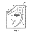
- the cooling article 10 and other components of thermal processing apparatus 12 can be part of a larger apparatus, such as the photothermographic imager 42 shown in Fig. 2.
- the photothermographic imager 42 can include a container 44 for holding sheets 14 of photothermographic material.
- Transport mechanisms 46 can transport sheets 14 from container 44 to an exposure station 48 and to thermal processing apparatus 12.
- the exposure station 48 scans a light beam onto sheet 14 in an image-wise pattern to create a latent image in the sheet.
- the thermal processing apparatus 12 heats the sheet 14 to a sufficient temperature for a sufficient duration to develop the latent image in the sheet to a visible image.
Landscapes
- Physics & Mathematics (AREA)
- General Physics & Mathematics (AREA)
- Photographic Developing Apparatuses (AREA)
- Heating, Cooling, Or Curing Plastics Or The Like In General (AREA)
- Treatment Of Fiber Materials (AREA)
- Processing And Handling Of Plastics And Other Materials For Molding In General (AREA)
Claims (18)
- Kühlung (10) zum Kühlen einer Bahn (14) aus thermisch bearbeitetem Material, mit:einer Platte (20) mit einer Fläche zum Aufnehmen einer Bahn thermisch bearbeiteten Materials, wobei die Fläche einen ersten Bereich (30) und einen zweiten Bereich (32) aufweist, und wobei die Bahn entlang der Fläche von deren erstem Bereich zu deren zweitem Bereich bewegt werden kann;einem im ersten Bereich der Fläche der Platte vorgesehenen thermisch isolierenden Material; undeinem im zweiten Bereich der Fläche der Platte vorgesehenen thermisch leitfähigen Material.
- Kühlung nach Anspruch 1, bei der das thermisch isolierende Material einen Wärmeleitkoeffizienten im Bereich von ungefähr 0 bis 1,44 Watt/(Meter Kelvin) und eine spezifische Wärme im Bereich von ungefähr 0 bis 5,0 Kilojoule/(Kilogramm · Kelvin) aufweist.
- Kühlung nach Anspruch 1, bei der das thermisch isolierende Material einen Wärmeleitkoeffizienten im Bereich von ungefähr 0 bis 0,029 Watt/(Meter · Kelvin) und eine spezifische Wärme im Bereich von ungefähr 0 bis 1,0 Kilojoule/(Kilogramm · Kelvin) aufweist.
- Kühlung nach Anspruch 1, bei der das thermisch isolierende Material natürlichen Filz aufweist.
- Kühlung nach Anspruch 1, bei der das thermisch isolierende Material synthetischen Filz aufweist.
- Kühlung nach Anspruch 1, bei der das thermisch isolierende Material ein Material auf Textilbasis aufweist.
- Kühlung nach Anspruch 1, bei der das thermisch isolierende Material ein Vliesmaterial aufweist.
- Kühlung nach Anspruch 1, bei der das thermisch isolierende Material eine auf dem ersten Bereich der Plattenfläche angeordnete Bahn aus thermisch isolierendem Material aufweist.
- Kühlung nach Anspruch 1, bei der das thermisch isolierende Material eine Bahn aus thermisch isolierendem Material mit einem ersten Ende, das zur Verbindung mit einer thermischen Bearbeitungsvorrichtung nahe einem Auslaß derselben dient, und einem zweiten Ende, das auf dem ersten Bereich der Plattenfläche angeordnet ist, wobei die Bahn aus thermisch isolierendem Material zum Stützen eines Bereichs der Bahn des thermisch bearbeiteten Materials während der Bewegung der Bahn des thermisch bearbeiteten Materials aus dem Auslaß der thermischen Bearbeitungsvorrichtung heraus ausgebildet ist.
- Vorrichtung (42) zum thermischen Bearbeiten einer Bahn (14) thermisch bearbeitbaren Materials, mit:einem Gehäuse;einem in dem Gehäuse angeordneten Erwärmungselement (12) zum Erwärmen der Bahn thermisch bearbeitbaren Materials; undeiner Kühlung (10) zum Kühlen der Bahn thermisch bearbeitbaren Materials während des Bewegens der Bahn thermisch bearbeitbaren Materials aus einem Auslaß des Gehäuses heraus, wobei die Kühlung eine nahe dem Auslaß des Gehäuses angeordnete Platte aufweist, die eine Fläche zum Aufnehmen der Bahn thermisch bearbeitbaren Materials aufweist, derart daß die Bahn thermisch bearbeitbaren Materials sich entlang der Fläche bewegt, wobei ein nahe dem Auslaß des Gehäuses angeordneter erster Bereich der Fläche der Platte ein thermisch isolierendes Material aufweist, und ein zweiter Bereich der Platte, der auf der dem Auslaß entgegengesetzten Seite des ersten Bereichs angeordnet ist, ein thermisch leitfähiges Material aufweist, und wobei die Bahn thermisch bearbeitbaren Materials das thermisch isolierende Material während der Bewegung im ersten Bereich berührt und das thermisch leitfähige Material während der Bewegung im zweiten Bereich berührt.
- Vorrichtung nach Anspruch 10, bei der das thermisch isolierende Material einen Wärmeleitkoeffizienten im Bereich von ungefähr 0 bis 1,44 Watt/(Meter · Kelvin) und eine spezifische Wärme im Bereich von ungefähr 0 bis 5,0 Kilojoule/(Kilogramm · Kelvin) aufweist.
- Vorrichtung nach Anspruch 10, bei der das thermisch isolierende Material einen Wärmeleitkoeffizienten im Bereich von ungefähr 0 bis 0,029 Watt/(Meter Kelvin) und eine spezifische Wärme im Bereich von ungefähr 0 bis 1,0 Kilojoule/(Kilogramm · Kelvin) aufweist.
- Vorrichtung nach Anspruch 10, bei der das thermisch isolierende Material natürlichen Filz aufweist.
- Vorrichtung nach Anspruch 10, bei der das thermisch isolierende Material synthetischen Filz aufweist.
- Vorrichtung nach Anspruch 10, bei der das thermisch isolierende Material ein Material auf Textilbasis aufweist.
- Vorrichtung nach Anspruch 10, bei der das thermisch isolierende Material ein Vliesmaterial aufweist.
- Vorrichtung nach Anspruch 10, bei der das thermisch isolierende Material eine auf dem ersten Bereich der Plattenfläche angeordnete Bahn aus thermisch isolierendem Material aufweist.
- Vorrichtung nach Anspruch 10, bei der das thermisch isolierende Material eine Bahn aus thermisch isolierendem Material mit einem ersten Ende, das zur Verbindung mit einer thermischen Bearbeitungsvorrichtung nahe einem Auslaß derselben dient, und einem zweiten Ende, das auf dem ersten Bereich der Plattenfläche angeordnet ist, wobei die Bahn aus thermisch isolierendem Material zum Stützen eines Bereichs der Bahn des thermisch bearbeiteten Materials während der Bewegung der Bahn des thermisch bearbeiteten Materials aus dem Auslaß der thermischen Bearbeitungsvorrichtung heraus ausgebildet ist.
Applications Claiming Priority (3)
| Application Number | Priority Date | Filing Date | Title |
|---|---|---|---|
| US08/539,856 US5699101A (en) | 1995-10-06 | 1995-10-06 | Article for cooling a sheet of thermally-processed material |
| US539856 | 1995-10-06 | ||
| PCT/US1996/014525 WO1997013182A1 (en) | 1995-10-06 | 1996-09-05 | Article for cooling a sheet of thermally-processed material |
Publications (2)
| Publication Number | Publication Date |
|---|---|
| EP0853773A1 EP0853773A1 (de) | 1998-07-22 |
| EP0853773B1 true EP0853773B1 (de) | 2001-01-17 |
Family
ID=24152944
Family Applications (1)
| Application Number | Title | Priority Date | Filing Date |
|---|---|---|---|
| EP96930804A Expired - Lifetime EP0853773B1 (de) | 1995-10-06 | 1996-09-05 | Vorrichtung zur kühlung eines thermisch entwickelten blattes |
Country Status (6)
| Country | Link |
|---|---|
| US (1) | US5699101A (de) |
| EP (1) | EP0853773B1 (de) |
| JP (1) | JP3655315B2 (de) |
| AU (1) | AU6972696A (de) |
| DE (1) | DE69611619T2 (de) |
| WO (1) | WO1997013182A1 (de) |
Families Citing this family (5)
| Publication number | Priority date | Publication date | Assignee | Title |
|---|---|---|---|---|
| US5849388A (en) * | 1996-02-02 | 1998-12-15 | Imation Corp. | Article, apparatus and method for cooling a thermally processed material |
| US6116794A (en) * | 1998-08-31 | 2000-09-12 | Eastman Kodak Company | Apparatus for cooling a thermally processed material |
| US6146028A (en) * | 1999-02-05 | 2000-11-14 | Eastman Kodak Company | Apparatus and method for cooling a thermally processed material |
| US7167193B2 (en) * | 2003-02-28 | 2007-01-23 | Eastman Kodak Company | Active cooling system for laser imager |
| US7924300B2 (en) | 2006-08-07 | 2011-04-12 | Carestream Health, Inc. | Processor for imaging media |
Family Cites Families (4)
| Publication number | Priority date | Publication date | Assignee | Title |
|---|---|---|---|---|
| US3628440A (en) * | 1969-01-27 | 1971-12-21 | Eastman Kodak Co | Apparatus for processing photographic material with radiation |
| US4485294A (en) * | 1983-03-18 | 1984-11-27 | Phoenix Medical Corporation | Developer for photothermographic paper |
| JPH03208048A (ja) * | 1990-01-10 | 1991-09-11 | Canon Inc | 改良熱現像法 |
| US5563681A (en) * | 1994-11-09 | 1996-10-08 | Minnesota Mining And Manufacturing Company | Article and method for cooling a sheet of material while minimizing wrinkling and curling within the sheet |
-
1995
- 1995-10-06 US US08/539,856 patent/US5699101A/en not_active Expired - Lifetime
-
1996
- 1996-09-05 EP EP96930804A patent/EP0853773B1/de not_active Expired - Lifetime
- 1996-09-05 AU AU69726/96A patent/AU6972696A/en not_active Abandoned
- 1996-09-05 JP JP51426397A patent/JP3655315B2/ja not_active Expired - Fee Related
- 1996-09-05 WO PCT/US1996/014525 patent/WO1997013182A1/en not_active Ceased
- 1996-09-05 DE DE69611619T patent/DE69611619T2/de not_active Expired - Lifetime
Also Published As
| Publication number | Publication date |
|---|---|
| JP3655315B2 (ja) | 2005-06-02 |
| WO1997013182A1 (en) | 1997-04-10 |
| JP2001525073A (ja) | 2001-12-04 |
| EP0853773A1 (de) | 1998-07-22 |
| DE69611619D1 (de) | 2001-02-22 |
| AU6972696A (en) | 1997-04-28 |
| DE69611619T2 (de) | 2001-06-13 |
| US5699101A (en) | 1997-12-16 |
Similar Documents
| Publication | Publication Date | Title |
|---|---|---|
| JP3296482B2 (ja) | 熱現像装置 | |
| US5665257A (en) | Flat bed thermophotographic film processor | |
| JPS6032178B2 (ja) | 写真材料乾燥法およびその装置 | |
| EP0853773B1 (de) | Vorrichtung zur kühlung eines thermisch entwickelten blattes | |
| US5587767A (en) | Digital film heat processor and method of developing digital film | |
| US5869806A (en) | Apparatus and method for thermally processing an imaging material employing means for bending the imaging material during thermal processing | |
| US5563681A (en) | Article and method for cooling a sheet of material while minimizing wrinkling and curling within the sheet | |
| US6041516A (en) | Article, apparatus and method for cooling a thermally processed material | |
| US6051813A (en) | Method for thermally processing an imaging material employing improved heating means | |
| EP0946898B1 (de) | Vorrichtung zur thermischen entwicklung von bildaufzeichnungsmaterial mit mittel zur reduzierung des schleiers auf dem aufzeichnungsmaterial während der entwicklung | |
| US5790069A (en) | Thermal Processor with air flow preventing structure | |
| US5986238A (en) | Apparatus and method for thermally processing an imaging material employing means for reducing fogging on the imaging material during thermal processing | |
| KR930005359B1 (ko) | 칼라 비디오 프린터 열정착부의 수상지 받침대 장치 | |
| JP2000250192A (ja) | 熱処理装置及びそれを利用した熱現像装置 | |
| JPH03259250A (ja) | 写真作成装置 | |
| JPH05216117A (ja) | 写真作成装置 | |
| JPH03259235A (ja) | 写真作成装置 |
Legal Events
| Date | Code | Title | Description |
|---|---|---|---|
| PUAI | Public reference made under article 153(3) epc to a published international application that has entered the european phase |
Free format text: ORIGINAL CODE: 0009012 |
|
| 17P | Request for examination filed |
Effective date: 19980325 |
|
| AK | Designated contracting states |
Kind code of ref document: A1 Designated state(s): DE FR GB |
|
| GRAG | Despatch of communication of intention to grant |
Free format text: ORIGINAL CODE: EPIDOS AGRA |
|
| RAP1 | Party data changed (applicant data changed or rights of an application transferred) |
Owner name: MINNESOTA MINING AND MANUFACTURING COMPANY |
|
| 17Q | First examination report despatched |
Effective date: 19990714 |
|
| GRAG | Despatch of communication of intention to grant |
Free format text: ORIGINAL CODE: EPIDOS AGRA |
|
| GRAH | Despatch of communication of intention to grant a patent |
Free format text: ORIGINAL CODE: EPIDOS IGRA |
|
| GRAH | Despatch of communication of intention to grant a patent |
Free format text: ORIGINAL CODE: EPIDOS IGRA |
|
| RAP1 | Party data changed (applicant data changed or rights of an application transferred) |
Owner name: EASTMAN KODAK COMPANY |
|
| GRAA | (expected) grant |
Free format text: ORIGINAL CODE: 0009210 |
|
| AK | Designated contracting states |
Kind code of ref document: B1 Designated state(s): DE FR GB |
|
| REF | Corresponds to: |
Ref document number: 69611619 Country of ref document: DE Date of ref document: 20010222 |
|
| ET | Fr: translation filed | ||
| PG25 | Lapsed in a contracting state [announced via postgrant information from national office to epo] |
Ref country code: GB Free format text: LAPSE BECAUSE OF NON-PAYMENT OF DUE FEES Effective date: 20010905 |
|
| PLBE | No opposition filed within time limit |
Free format text: ORIGINAL CODE: 0009261 |
|
| STAA | Information on the status of an ep patent application or granted ep patent |
Free format text: STATUS: NO OPPOSITION FILED WITHIN TIME LIMIT |
|
| 26N | No opposition filed | ||
| PGFP | Annual fee paid to national office [announced via postgrant information from national office to epo] |
Ref country code: FR Payment date: 20050902 Year of fee payment: 10 |
|
| REG | Reference to a national code |
Ref country code: FR Ref legal event code: ST Effective date: 20070531 |
|
| PG25 | Lapsed in a contracting state [announced via postgrant information from national office to epo] |
Ref country code: FR Free format text: LAPSE BECAUSE OF NON-PAYMENT OF DUE FEES Effective date: 20061002 |
|
| PGFP | Annual fee paid to national office [announced via postgrant information from national office to epo] |
Ref country code: DE Payment date: 20140930 Year of fee payment: 19 |
|
| REG | Reference to a national code |
Ref country code: DE Ref legal event code: R119 Ref document number: 69611619 Country of ref document: DE |
|
| PG25 | Lapsed in a contracting state [announced via postgrant information from national office to epo] |
Ref country code: DE Free format text: LAPSE BECAUSE OF NON-PAYMENT OF DUE FEES Effective date: 20160401 |