EP0853965A1 - Unité de filtre ainsi que procédé et installation pour sa préparation - Google Patents
Unité de filtre ainsi que procédé et installation pour sa préparation Download PDFInfo
- Publication number
- EP0853965A1 EP0853965A1 EP98650004A EP98650004A EP0853965A1 EP 0853965 A1 EP0853965 A1 EP 0853965A1 EP 98650004 A EP98650004 A EP 98650004A EP 98650004 A EP98650004 A EP 98650004A EP 0853965 A1 EP0853965 A1 EP 0853965A1
- Authority
- EP
- European Patent Office
- Prior art keywords
- blank
- filter
- feedstock
- corner
- filter element
- Prior art date
- Legal status (The legal status is an assumption and is not a legal conclusion. Google has not performed a legal analysis and makes no representation as to the accuracy of the status listed.)
- Withdrawn
Links
- 238000000034 method Methods 0.000 title claims description 17
- 238000004519 manufacturing process Methods 0.000 title claims description 5
- 238000009432 framing Methods 0.000 claims abstract description 13
- 238000001914 filtration Methods 0.000 claims abstract description 10
- 239000000463 material Substances 0.000 claims description 34
- 239000003292 glue Substances 0.000 claims description 16
- 238000005520 cutting process Methods 0.000 claims description 14
- 239000000853 adhesive Substances 0.000 claims description 9
- 230000001070 adhesive effect Effects 0.000 claims description 9
- 238000004026 adhesive bonding Methods 0.000 claims description 5
- 238000002360 preparation method Methods 0.000 claims description 5
- 238000004080 punching Methods 0.000 claims description 5
- 230000000717 retained effect Effects 0.000 claims description 3
- 230000003014 reinforcing effect Effects 0.000 claims description 2
- 239000011111 cardboard Substances 0.000 description 16
- 230000004075 alteration Effects 0.000 description 1
- 230000015572 biosynthetic process Effects 0.000 description 1
- 239000012467 final product Substances 0.000 description 1
- 239000012943 hotmelt Substances 0.000 description 1
- 238000005304 joining Methods 0.000 description 1
- 239000000203 mixture Substances 0.000 description 1
- 238000012986 modification Methods 0.000 description 1
- 230000004048 modification Effects 0.000 description 1
- 238000004806 packaging method and process Methods 0.000 description 1
- 239000007921 spray Substances 0.000 description 1
- 230000007704 transition Effects 0.000 description 1
- 239000002699 waste material Substances 0.000 description 1
Images



Classifications
-
- B—PERFORMING OPERATIONS; TRANSPORTING
- B01—PHYSICAL OR CHEMICAL PROCESSES OR APPARATUS IN GENERAL
- B01D—SEPARATION
- B01D46/00—Filters or filtering processes specially modified for separating dispersed particles from gases or vapours
- B01D46/52—Particle separators, e.g. dust precipitators, using filters embodying folded corrugated or wound sheet material
- B01D46/521—Particle separators, e.g. dust precipitators, using filters embodying folded corrugated or wound sheet material using folded, pleated material
-
- B—PERFORMING OPERATIONS; TRANSPORTING
- B01—PHYSICAL OR CHEMICAL PROCESSES OR APPARATUS IN GENERAL
- B01D—SEPARATION
- B01D46/00—Filters or filtering processes specially modified for separating dispersed particles from gases or vapours
- B01D46/0001—Making filtering elements
-
- B—PERFORMING OPERATIONS; TRANSPORTING
- B01—PHYSICAL OR CHEMICAL PROCESSES OR APPARATUS IN GENERAL
- B01D—SEPARATION
- B01D46/00—Filters or filtering processes specially modified for separating dispersed particles from gases or vapours
- B01D46/0002—Casings; Housings; Frame constructions
- B01D46/0016—Folded frame or housing constructions
Definitions
- the present invention relates to a filter unit and to an apparatus and a process for preparing a filter unit.
- it relates to a panel filter and to an efficient method of producing panel filters.
- Panel filters comprise a filter mesh of appropriate size, porosity and composition for the particular use to which the filter is to be put, surrounded by a frame element which is sized to fit across the inlet or outlet of a particular air space.
- the frame is usually made from a disposable material, such as cardboard.
- the filter may be pleated and accordingly the frame element has a depth dimension to accommodate the height (depth) of the pleats, in addition to length and width dimensions.
- Filters are required in a large number of industrial, commercial, medical, household and other premises where there is a necessity or a desire to filter either incoming or outgoing air. Unfortunately, inlets and outlets are of non-standard sizes and thus, the panel filters must be made to the particular specifications necessary for individual cases.
- the present invention seeks to provide an efficient process for constructing panel filters, in which waste is minimised and operator-time is managed so as to achieve high productivity.
- the invention also seeks to provide a process for producing the filters and an apparatus for operating the process.
- the present invention provides an apparatus for preparing a panel filter, comprising;
- the apparatus includes a plurality of workstations and means for transferring feedstock or blank material between the workstations, the workstations comprising:
- the invention also provides a panel filter made by the above apparatus, the filter optionally including at least one filter reinforcing element laid against or fixed to at least one of the opposed faces of the filter element to lend rigidity to the panel filter, the or each element preferably being retained between the face and a section of the blank which adheres to the face.
- the invention also provides a process for preparing a panel filter, comprising:
- the invention further provides a blank for forming a frame about a filter element, the blank comprising a length of a framing material sized to match the length of at least one of four edges of the filter element and having a depth greater than the depth of the filter element, the blank having at least one pair of opposed slots, each slot extending from a longitudinal edge of the blank at right angles thereto and a corner score mark etched on an inner face of the blank and extending between the bases of the pair of slots, the blank further including a pair of flange score marks disposed parallel to one another and to the longitudinal edges of the blank, the flange score marks being formed on the inner face of the blank and being spaced apart from one another by a distance corresponding to the depth of the filter element, so that in use as a framing element, the blank lies against at least a portion of two edges of the filter element with the slots and corner scores extending about the corner between said two edges, and a flange between a flange score mark and its nearest longitudinal edge of the blank being folded so as
- depth of the filter refers to the thickness of the filter or, where the filter is folded, for example, in a waveform of pleated formation, “depth” refers to the height of the waves or pleats.
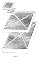
- a pair of frame blanks 1, 2 are cut from a roll of frame material.
- the frame material comprises a stiff, robust, pliable material such as cardboard.
- Various depths of cardboard may be provided and the desired depth will be selected, depending on the depth of the pleats of the pleated filter F to be accommodated within the final frame element.
- cardboards of depth of 7.62 cm, 9.8 cm and 15.24 cm (1, 2 and 4 inch, respectively) are used to accommodate filter of pleat depths 2.54 cm, 5.08 cm and 10.16 cm.
- Each frame blank 1, 2 is cut to a length which is slightly greater than that of two continuous sides of the filter F.
- each blank 1, 2 is greater than the depth of the filter F so that the blank may be folded against the upper and lower pleated surfaces of the filter F.
- each blank 1, 2 is provided with a pair of parallel score marks 4, 5 spaced apart by a distance equal to the depth of the filter along the longitudinal axis of the blank. These score marks divide the blank into three sections, an upper flange 6, a middle section 7 and a lower flange 8.
- the flanges typically are 2.34 cm in depth.
- each blank 1, 2 Adjacent an end 9 of each blank 1, 2 is provided a pair of slots 10 extending through the upper and lower sections 6, 8 as far as the score marks 4, 5 respectively.
- a second similar pair of slots 11 is provided, spaced from the slots 10 along the longitudinal axis of the blanks 1, 2 by a distance equal to the length L1 of the filter F to define an area 20 between the pairs of slots 10, 11.
- the slots 10, 11 define the corners of the panel filter.
- Each blank also includes an area 30 extending between slots 11 and end 12, equal to the length L2 of the filter.
- the area between slots 10 and end 9 defines a corner tab 40.
- Score marking 13 are provided along the middle section 7 joining each pair of slots 10, 11.
- each blank is laid against the filter F, one to either side of the filter along the length L1.
- a pair of cross-pieces 14 is arranged in an X-shape and laid on the upper-facing pleated face of the filter.
- a second pair of cross-pieces 14 is likewise laid on the opposing pleated face of the filter.
- the cross-pieces 14 are securely fixed to the filter by gluing.
- area 20 of the blank is arranged so that the middle section 7 lies against the side L1 of the filter, as shown in Figure 1.
- tabs 40 and flanges 6 and 8 of area 20 and tabs 40 are folded toward the filter about the respective score marks 13, 4 and 5.
- the next step is to fold areas 30 so that their middle sections 7 lie against the sides L2 of the filter and overlie tabs 40.
- the upper and lower flanges 6, 8 of area 30 are then folded about the score marks 4, 5 to overlie the filter, flanges 6 and 8 of the tabs 40 and the ends of flanges 6, 8 of area 20.
- the various elements are retained in their folded positions by suitable fixing means, such as adhesive or staples and preferably by adhesive.
- the adhesive comprises a hot melt glue which is applied to the blanks 1, 2 from spray nozzles fed from a reservoir of glue.
- Cross-pieces 14 are optional to the assembly of the filter unit. They may be used as described above, or in any alternative suitable configuration or pattern, when it is desirable to lend extra rigidity to the filter unit, for example when a pleated filter is used. In particular, where a relatively large filter is to be used and/or where the filter is used to filter a body of air which is flowing fast, then cross-pieces of some sort are usually necessary to prevent the filter from being blown away from the sides of its frame. This would of course be undesirable as any gaps between the filter and frame would allow unfiltered air to flow past the filter.
- Figure 4 shows a number of assembled disposable panel filters of varying sizes and shapes and with and without cross pieces 14.
- FIG. 7 is a flow sheet illustrating the various process steps undertaken by the apparatus.
- the apparatus includes a number of stations, each of which carries out a particular process step or set of process steps.
- the overall operation of the apparatus is controlled by a programmable logic controller (PLC) (not shown) with panel views P.
- PLC programmable logic controller
- An operator programs the PLC with information concerning the panel filters to be produced including the length, width and depth dimensions of the required panel filters, the number of units to be produced, order number, identification number, and/or proprietary information to appear on the panel filters, etc.
- the apparatus is then operated under the control of the PLC to produce the desired number of filters to desired specifications.
- the PLC may be programmed with a number of different jobs, so that the transition from production of one type of filter to a different one can be effected without interruption.
- a loading station 400 includes a frame 410 which can accommodate rolls of cardboard of different dimensions. Holders 411, 412 and 413 hold rolls of cardboard of widths 7.62 cm, 9.8 cm and 15.24 cm respectively. Under the control of the PLC, cardboard is drawn from the roll on the appropriate holder 411, 412 or 413 and led via rollers 414, 415 to the truing device 416 and guide 417. The truing device 416 and guide 417 ensure that the cardboard is properly centred and disposed for passing the punching station.
- the punching station 500 comprises three punch sets 511, 512, 513 which operate to punch out opposing segments of cardboard from the longitudinal edges of the cardboard so as to create the pairs of slots 10, 11.
- Punch sets 511, 512 and 513 create slots in the cardboard widths 7.62 cm, 9.8 cm and 15.24 cm respectively and in each case the slots created extend at right angles to the longitudinal edge of the cardboard and have a depth of about 2.54 cm from that longitudinal edge.
- the appropriate punch set is activated as the cardboard passes beneath it so as to create the pairs of opposing slots at the specified spacings. As described above, these slots constitute the eventual corner areas of the finished panel filters.
- the punched board then passes an optional marking station at which an ink jet 600 is operated to place the desired printed information on that flat side of the cardboard which. in the final assembled panel filter, faces outwardly.
- the cardboard is transferred to the scoring device 650 which produces the score marks 4, 5.
- the scored board passes to the corner score station 660, at which the corner score marks 13 are introduced.
- the boards are completed by passage over the cutting section 670, which cuts the board at the required position to give a blank 1 or 2, under control of the PLC.
- the PLC is programmed in such a way that the advancing roll of cardboard is formed and cut sequentially into a blank 1, followed by a blank 2, this sequence repeating until a sufficient number of blanks 1, 2 has been completed to prepare the desired number of panel filters.
- the next step in the sequence is the transfer of the prepared blanks to the picking and gluing station 700.
- This station comprises a pair of parallel pickers, one left picker 701 and one right picker 702.
- Each picker 701, 702 comprises a flat surface sized to allow the blank, 1, 2 respectively to lie on it.
- the blanks 1, 2 lie flat as they leave the cutting station 670.
- a blank 1 is transferred onto the left picker 701 and suction pads (not shown) on the picker are activated to contact the outer surface of the blank 1 so as to hold the blank 1 by suction.
- the left picker 701 pivots so that the blank 1 is rotated about its longitudinal axis from a horizontal position to a vertical position.
- the blank 1 continues to advance and passes a left glue nozzle 703 at which glue is sprayed onto the exposed inner surface of the blank 1, that is to say, the surface which in the final panel filter, contacts the filter element.
- the transfer of the blank 1 is assisted by the provision of a number of suction pads along the length of the picker 701 which are deployed sequentially under the control of the PLC to take up and grip the advancing blank 1.
- the blank 1 exits the station 700 and is transferred to the assembly station 800. It is followed into the station 700 by a blank which is picked up by the suction pads of the right picker 702, and pivoted about its longitudinal axis. Glue is applied to the inner surface of blank 2 by glue nozzle 704 as the blank is advanced with the assistance of the suction pads.
- the blank 2 then enters the assembly station 800.
- the blanks 1, 2 are held with the glued surfaces facing one another, substantially in the relative positions shown in Figure 1.
- a filter element prepared at carousel 900 is then introduced.
- Carousel 900 comprises a rotatable platform having a pair of feed units 901, 902.
- An operator O takes a pair of cross-pieces 14 and applies glue to one side of each of them from glue nozzle 950. He then places the glued cross-pieces onto feed unit 901 and lays a filter unit on top so that the underside of the filter is attached to the cross-pieces 14. Then, he places a second set of glued cross pieces 14 onto the upper-facing surface of the filter. This completes the preparation of the filter, which is then ready to be assembled with the blanks 1, 2 to form the completed panel filter.
- the operator next actuates the PLC to rotate the carousel about the vertical axis A by 180°, thus moving the charged feed unit 901 from the position shown in Figure 6 to that shown in Figure 5.
- empty feed unit 902 is rotated away from the assembly station 800 back to the operator to be charged with a fresh filter unit.
- the charged feed unit 901 advances into the assembly station 800, bringing the prepared filter unit with it.
- a series of levers and actuators (not shown) then carry out the steps described in relation to Figures 1 to 3, so as to encase and seal the prepared filter in the prepared, glue coated blanks 1, 2.
- the feed unit 901 is withdrawn without the completed panel filter, which falls onto a stacking jig 860 underneath the assembly station 800.
- a stacking jig 860 underneath the assembly station 800.
- they are transferred from the stacking jig 860 onto a conveyor belt 870 ( Figure 6) and removed for grouping packaging.
Landscapes
- Chemical & Material Sciences (AREA)
- Chemical Kinetics & Catalysis (AREA)
- Filtering Materials (AREA)
Applications Claiming Priority (2)
| Application Number | Priority Date | Filing Date | Title |
|---|---|---|---|
| IE970022 | 1997-01-13 | ||
| IES970022 IES79447B2 (en) | 1997-01-13 | 1997-01-13 | A filter unit and apparatus and process for manufacturing same |
Publications (1)
| Publication Number | Publication Date |
|---|---|
| EP0853965A1 true EP0853965A1 (fr) | 1998-07-22 |
Family
ID=11041349
Family Applications (1)
| Application Number | Title | Priority Date | Filing Date |
|---|---|---|---|
| EP98650004A Withdrawn EP0853965A1 (fr) | 1997-01-13 | 1998-01-13 | Unité de filtre ainsi que procédé et installation pour sa préparation |
Country Status (2)
| Country | Link |
|---|---|
| EP (1) | EP0853965A1 (fr) |
| IE (1) | IES79447B2 (fr) |
Cited By (5)
| Publication number | Priority date | Publication date | Assignee | Title |
|---|---|---|---|---|
| WO2001047619A1 (fr) * | 1999-12-23 | 2001-07-05 | Interfilta (Uk) Limited | Groupe de filtration d'air |
| CN105214391A (zh) * | 2015-11-04 | 2016-01-06 | 苏州艾美乐净化科技有限公司 | 板式过滤器的加工工艺 |
| CN106268062A (zh) * | 2016-09-28 | 2017-01-04 | 苏州国立洁净技术有限公司 | 一种过滤器生产工艺 |
| CN116367907A (zh) * | 2021-03-01 | 2023-06-30 | 王洁芳 | 可重用的过滤器系统和框架、其组装和运输方法及其用途 |
| CN120288314A (zh) * | 2025-06-13 | 2025-07-11 | 苏州国立洁净技术有限公司 | 一种层叠过滤器单体成品自动化生产线上的包装装箱装置及其包装方法 |
Citations (3)
| Publication number | Priority date | Publication date | Assignee | Title |
|---|---|---|---|---|
| GB1036323A (en) * | 1963-08-20 | 1966-07-20 | Farr Co | Method of manufacturing a pleated air filter cartridge |
| WO1988003833A1 (fr) * | 1986-11-17 | 1988-06-02 | Flodins Filter Ab | Procede de production de filtres et filtre produit a l'aide dudit procede |
| DE19503024A1 (de) * | 1994-02-02 | 1995-08-03 | Ac Delco Systems Overseas Corp | Luftfilter |
-
1997
- 1997-01-13 IE IES970022 patent/IES79447B2/en not_active IP Right Cessation
-
1998
- 1998-01-13 EP EP98650004A patent/EP0853965A1/fr not_active Withdrawn
Patent Citations (3)
| Publication number | Priority date | Publication date | Assignee | Title |
|---|---|---|---|---|
| GB1036323A (en) * | 1963-08-20 | 1966-07-20 | Farr Co | Method of manufacturing a pleated air filter cartridge |
| WO1988003833A1 (fr) * | 1986-11-17 | 1988-06-02 | Flodins Filter Ab | Procede de production de filtres et filtre produit a l'aide dudit procede |
| DE19503024A1 (de) * | 1994-02-02 | 1995-08-03 | Ac Delco Systems Overseas Corp | Luftfilter |
Cited By (6)
| Publication number | Priority date | Publication date | Assignee | Title |
|---|---|---|---|---|
| WO2001047619A1 (fr) * | 1999-12-23 | 2001-07-05 | Interfilta (Uk) Limited | Groupe de filtration d'air |
| CN105214391A (zh) * | 2015-11-04 | 2016-01-06 | 苏州艾美乐净化科技有限公司 | 板式过滤器的加工工艺 |
| CN106268062A (zh) * | 2016-09-28 | 2017-01-04 | 苏州国立洁净技术有限公司 | 一种过滤器生产工艺 |
| CN116367907A (zh) * | 2021-03-01 | 2023-06-30 | 王洁芳 | 可重用的过滤器系统和框架、其组装和运输方法及其用途 |
| CN120288314A (zh) * | 2025-06-13 | 2025-07-11 | 苏州国立洁净技术有限公司 | 一种层叠过滤器单体成品自动化生产线上的包装装箱装置及其包装方法 |
| CN120288314B (zh) * | 2025-06-13 | 2025-08-05 | 苏州国立洁净技术有限公司 | 一种层叠过滤器单体成品自动化生产线上的包装装箱装置及其包装方法 |
Also Published As
| Publication number | Publication date |
|---|---|
| IES970022A2 (en) | 1998-05-06 |
| IES79447B2 (en) | 1998-05-06 |
Similar Documents
| Publication | Publication Date | Title |
|---|---|---|
| EP3307624B1 (fr) | Machine pour la fabrication automatique d'emballage personnalise | |
| DE3148443A1 (de) | Schachtel mit sichtfenster sowie verfahren und vorrichtung zur herstellung einer solchen schachtel | |
| EP2508353A2 (fr) | Machine destinée à la fabrication de livres, notamment livres photo et/ou livres illustrés | |
| US4262939A (en) | Slide chart manufacture | |
| EP0705635A1 (fr) | Procédé de production de filtres | |
| DE102007018023A1 (de) | Verfahren und Einrichtung zum maschinellen Herstellen von Buchdecken für Einzelbücher und Kleinstauflagen unterschiedlicher Formatgrößen | |
| EP0853965A1 (fr) | Unité de filtre ainsi que procédé et installation pour sa préparation | |
| US4210067A (en) | Method of and apparatus for making air filters | |
| EP2221171A1 (fr) | Procédé et dispositif de fabrication de boîtes de papier ou de carton | |
| DE2418694A1 (de) | Verfahren und vorrichtung zur herstellung von klapp- oder stuelpdeckelschachteln | |
| EP0234349B1 (fr) | Dispositif pour empiler des coupons de carton ondulé double face | |
| EP4034390B1 (fr) | Dispositif et procédé de fabrication automatique de couvertures de reliures de livres et/ou de couvertures de boîtes | |
| US20220118788A1 (en) | Book production system and method | |
| US7007601B2 (en) | High speed mounting and printing for colored chips on a sheet | |
| US9919834B2 (en) | Pallet construction line and assembly | |
| EP0792212B1 (fr) | Procédé et appareil pour la production des découpes pour cartons | |
| US20080268195A1 (en) | Die-cut and method of manufacturing or assembling die-cuts from the components thereof | |
| EP0343522A2 (fr) | Procédé et machine de reliure automatique pour exemplaires uniques | |
| KR20230159681A (ko) | 접시-형상 제품 패키지를 제조하기 위한 장치 및 방법 | |
| CA2164304A1 (fr) | Appareil pour le formage d'articles en feuilles | |
| EP2718096B1 (fr) | Liaison locale de feuilles l'une sur l'autre, et methode et appareil destines a realiser ladite liaison | |
| EP0562432B1 (fr) | Procédé et dispositif pour le déchargement de paquets de feuilles d'une palette ou analogue | |
| CH687605A5 (de) | Verfahren und Anlage zum Herstellen von Buechern oder Broschueren. | |
| DE102018005986A1 (de) | Verfahren und Vorrichtung zum Beziehen biegesteifer Teile mit biegeschlaffen Nutzen | |
| DE2843506A1 (de) | Verfahren zur herstellung von mit deckeln versehenen schachteln, einrichtung zur durchfuehrung des verfahrens und mit dem verfahren erhaltene schachteln |
Legal Events
| Date | Code | Title | Description |
|---|---|---|---|
| PUAI | Public reference made under article 153(3) epc to a published international application that has entered the european phase |
Free format text: ORIGINAL CODE: 0009012 |
|
| AK | Designated contracting states |
Kind code of ref document: A1 Designated state(s): DE GB IE |
|
| AX | Request for extension of the european patent |
Free format text: AL;LT;LV;MK;RO;SI |
|
| 17P | Request for examination filed |
Effective date: 19990122 |
|
| AKX | Designation fees paid |
Free format text: DE GB IE |
|
| RBV | Designated contracting states (corrected) |
Designated state(s): DE GB IE |
|
| STAA | Information on the status of an ep patent application or granted ep patent |
Free format text: STATUS: THE APPLICATION IS DEEMED TO BE WITHDRAWN |
|
| 18D | Application deemed to be withdrawn |
Effective date: 20020801 |