EP0854005B1 - Procédé de perçage au moyen d'un faisceau d'énergie, ainsi que procédé de contrôle de perforations de ventilation - Google Patents
Procédé de perçage au moyen d'un faisceau d'énergie, ainsi que procédé de contrôle de perforations de ventilation Download PDFInfo
- Publication number
- EP0854005B1 EP0854005B1 EP98300208A EP98300208A EP0854005B1 EP 0854005 B1 EP0854005 B1 EP 0854005B1 EP 98300208 A EP98300208 A EP 98300208A EP 98300208 A EP98300208 A EP 98300208A EP 0854005 B1 EP0854005 B1 EP 0854005B1
- Authority
- EP
- European Patent Office
- Prior art keywords
- holes
- cooling
- drilling
- laser
- hollow interior
- Prior art date
- Legal status (The legal status is an assumption and is not a legal conclusion. Google has not performed a legal analysis and makes no representation as to the accuracy of the status listed.)
- Expired - Lifetime
Links
- 238000000034 method Methods 0.000 title claims description 34
- 238000005553 drilling Methods 0.000 title claims description 23
- 238000001816 cooling Methods 0.000 title description 47
- 239000000463 material Substances 0.000 claims description 42
- 230000000903 blocking effect Effects 0.000 claims description 10
- 239000000203 mixture Substances 0.000 claims description 4
- 238000005495 investment casting Methods 0.000 claims description 3
- 238000007689 inspection Methods 0.000 description 9
- 238000001514 detection method Methods 0.000 description 3
- 238000012544 monitoring process Methods 0.000 description 3
- 230000004888 barrier function Effects 0.000 description 2
- 238000009826 distribution Methods 0.000 description 2
- 238000000960 laser cooling Methods 0.000 description 2
- 238000004519 manufacturing process Methods 0.000 description 2
- 230000001052 transient effect Effects 0.000 description 2
- WYTGDNHDOZPMIW-RCBQFDQVSA-N alstonine Natural products C1=CC2=C3C=CC=CC3=NC2=C2N1C[C@H]1[C@H](C)OC=C(C(=O)OC)[C@H]1C2 WYTGDNHDOZPMIW-RCBQFDQVSA-N 0.000 description 1
- 239000012612 commercial material Substances 0.000 description 1
- 230000007547 defect Effects 0.000 description 1
- 230000002950 deficient Effects 0.000 description 1
- 230000008030 elimination Effects 0.000 description 1
- 238000003379 elimination reaction Methods 0.000 description 1
- 230000008020 evaporation Effects 0.000 description 1
- 238000001704 evaporation Methods 0.000 description 1
- 238000003384 imaging method Methods 0.000 description 1
- 238000002844 melting Methods 0.000 description 1
- 230000008018 melting Effects 0.000 description 1
- 238000003908 quality control method Methods 0.000 description 1
- 230000005855 radiation Effects 0.000 description 1
- 238000001931 thermography Methods 0.000 description 1
Images


Classifications
-
- G—PHYSICS
- G01—MEASURING; TESTING
- G01N—INVESTIGATING OR ANALYSING MATERIALS BY DETERMINING THEIR CHEMICAL OR PHYSICAL PROPERTIES
- G01N21/00—Investigating or analysing materials by the use of optical means, i.e. using sub-millimetre waves, infrared, visible or ultraviolet light
- G01N21/84—Systems specially adapted for particular applications
- G01N21/88—Investigating the presence of flaws or contamination
- G01N21/95—Investigating the presence of flaws or contamination characterised by the material or shape of the object to be examined
- G01N21/956—Inspecting patterns on the surface of objects
- G01N21/95692—Patterns showing hole parts, e.g. honeycomb filtering structures
-
- B—PERFORMING OPERATIONS; TRANSPORTING
- B23—MACHINE TOOLS; METAL-WORKING NOT OTHERWISE PROVIDED FOR
- B23K—SOLDERING OR UNSOLDERING; WELDING; CLADDING OR PLATING BY SOLDERING OR WELDING; CUTTING BY APPLYING HEAT LOCALLY, e.g. FLAME CUTTING; WORKING BY LASER BEAM
- B23K26/00—Working by laser beam, e.g. welding, cutting or boring
- B23K26/18—Working by laser beam, e.g. welding, cutting or boring using absorbing layers on the workpiece, e.g. for marking or protecting purposes
-
- B—PERFORMING OPERATIONS; TRANSPORTING
- B23—MACHINE TOOLS; METAL-WORKING NOT OTHERWISE PROVIDED FOR
- B23K—SOLDERING OR UNSOLDERING; WELDING; CLADDING OR PLATING BY SOLDERING OR WELDING; CUTTING BY APPLYING HEAT LOCALLY, e.g. FLAME CUTTING; WORKING BY LASER BEAM
- B23K26/00—Working by laser beam, e.g. welding, cutting or boring
- B23K26/36—Removing material
- B23K26/38—Removing material by boring or cutting
- B23K26/382—Removing material by boring or cutting by boring
- B23K26/389—Removing material by boring or cutting by boring of fluid openings, e.g. nozzles, jets
-
- G—PHYSICS
- G01—MEASURING; TESTING
- G01N—INVESTIGATING OR ANALYSING MATERIALS BY DETERMINING THEIR CHEMICAL OR PHYSICAL PROPERTIES
- G01N21/00—Investigating or analysing materials by the use of optical means, i.e. using sub-millimetre waves, infrared, visible or ultraviolet light
- G01N21/17—Systems in which incident light is modified in accordance with the properties of the material investigated
- G01N21/25—Colour; Spectral properties, i.e. comparison of effect of material on the light at two or more different wavelengths or wavelength bands
- G01N21/31—Investigating relative effect of material at wavelengths characteristic of specific elements or molecules, e.g. atomic absorption spectrometry
- G01N21/33—Investigating relative effect of material at wavelengths characteristic of specific elements or molecules, e.g. atomic absorption spectrometry using ultraviolet light
-
- G—PHYSICS
- G01—MEASURING; TESTING
- G01N—INVESTIGATING OR ANALYSING MATERIALS BY DETERMINING THEIR CHEMICAL OR PHYSICAL PROPERTIES
- G01N21/00—Investigating or analysing materials by the use of optical means, i.e. using sub-millimetre waves, infrared, visible or ultraviolet light
- G01N21/84—Systems specially adapted for particular applications
- G01N21/88—Investigating the presence of flaws or contamination
- G01N21/8803—Visual inspection
-
- G—PHYSICS
- G01—MEASURING; TESTING
- G01N—INVESTIGATING OR ANALYSING MATERIALS BY DETERMINING THEIR CHEMICAL OR PHYSICAL PROPERTIES
- G01N21/00—Investigating or analysing materials by the use of optical means, i.e. using sub-millimetre waves, infrared, visible or ultraviolet light
- G01N21/84—Systems specially adapted for particular applications
- G01N21/88—Investigating the presence of flaws or contamination
- G01N21/95—Investigating the presence of flaws or contamination characterised by the material or shape of the object to be examined
- G01N21/9515—Objects of complex shape, e.g. examined with use of a surface follower device
Definitions
- the present invention relates to the detection of blocked or defective laser drilled cooling holes see US-A-5 011 626 for example and, more particularly, to method for beam drilling and inspecting the cooling holes of a gas turbine engine airfoil using a black light to illuminate a fluorescent laser beam blocking material used during beam and, more particularly, laser drilling of the holes.
- Gas turbine engines have hollow airfoil turbine blades and vanes representative of hollow articles having laser or otherwise beam drilled cooling holes to which this patent is directed.
- a gas turbine engine blade 10 and more particularly its airfoil 11 has a multiplicity of cooling channels or holes 12 formed therein by laser drilling to permit cooling of the blade during engine operation.
- the cooling holes 12 extend from an exterior surface 14 of a wall 15 of the blade 10 into a hollow interior 16 or plenum of the blade 10.
- the blade hollow interior includes a plurality of interior walls 18 or baffles to direct cooling air along a serpentine cooling circuit 19 further indicated by arrows 20, through the interior of blade 10 and out cooling holes 12 to create cooling air streams, indicated by arrows 22.
- Cooling air 20 absorbs heat within the interior 16 of blade 10 and also from the walls surrounding cooling holes 12 and cooling air streams 22 exiting holes 12 flow over the exterior surface 14 to further cool the blade.
- the cooling holes 12 In order to function properly, the cooling holes 12 must be constructed to a known configuration because the distribution of airflow must be controlled to achieve proper cooling of the blade during engine operation. Thus, the cooling holes must not be blocked or even partially blocked to provide sufficient and uniform cooling air distribution through blade interior 16 and across the exterior 14 of blade 10. Laser drilling and other beam drilling processes create melted material and the holes may become blocked after the drilling procedure is finished. Sometimes individual holes in an array of holes are not drilled through completely or missed altogether due to an error in the drilling process or faulty equipment. Therefore, the inspection of cooling holes 12 to detect blockages is very important in the process of making such articles, particularly from a quality control standpoint. Inspection of cooling holes 12 to detect blockages is difficult because of the small size of the holes; a typical hole diameter is about 12 mils (0.3 mm.).
- a wire or pin diameter gage is typically employed to inspect the cooling holes for blockage but this method is time consuming, tedious and labor intensive. Additionally, the wire or pin gauges can break and pieces of the gauge can become trapped within the interior plenum or the cooling hole and, therefore, block the hole adding further time and costs to the manufacturing process.
- a method and apparatus for inspecting cooling holes using infrared thermography is disclosed and claimed in U.S. Patent No. 4,644,162, issued Feb. 17, 1987. This patent discloses forcing a heated gas through a relatively cooler cooling hole, measuring the infrared signature of the cooling holes during the transient with a scanning infrared radiometer, and comparing the measured radiation intensity with a reference.
- Another method and apparatus for inspecting a channel through a workpiece or cooling holes through the surface of a gas turbine engine are disclosed in U.S. Patent No. 5,111,046 which uses imaging with an infrared radiometer to generate a series of images of the blade during both heat-up and cool-down cycles.
- a selected group of parameters are determined from the series of images generated by the IR radiometer and defects within the cooling holes may then be detected by analyzing the parameters, such as a transient response of the infrared signature of the cooling holes during both the heat-up and the cool-down cycles. Again, both these methods though very useful are very expensive and time consuming to incorporate in a production line such as is the intended use of the present invention.
- U.S. Patent No. 4,873,414 A method and apparatus real-time cooling hole size monitoring and laser control to enhance the quality and consistency of cooling holes is disclosed in U.S. Patent No. 4,873,414. This method and apparatus monitor light reflected back from the hole to provide a means for monitoring the size of the hole being drilled by the laser and for controlling the laser beam.
- the barrier material includes material which will disperse the laser light and material which will emit light when exposed to the laser light.
- the light emitter materials could be luminescent materials, phosphorescent materials, or fluorescent materials.
- U.S. Patent No. 5,054,087 discloses a process for optically checking perforations in a hollow article, particularly the micro-perforations in the vicinity of the leading or trailing edge of a hollow turbine blade for a turbo-shaft engine. This process comprises illuminating the inner cavity (hollow interior) of the article through an opening at one end thereof and scanning the length of the article by means of a video camera. The video signals are then processed and compared to signals with a predetermined train of reference signals derived from a standard article.
- Such a system may work for non-serpentine cooling circuits but cannot reach interior cavities of the serpentine type or any other type of hidden cavities and cooling circuits inside of the cooled airfoil. Often there is no way for light to be directed into the interior cavities of leading edge cooling chambers to which the cooling holes are laser drilled.
- the present invention is directed to overcoming these shortcomings and provide an accurate, quick, and inexpensive method of inspecting laser drilled cooling holes.
- a method of forming and inspecting beam drilled holes and, in particular, laser beam drilled holes, in an article, such as a turbine blade or vane airfoil with a hollow interior includes (a) filling the hollow interior with a beam blocking material having fluorescent material, (b) beam drilling the holes in the wall through to the hollow interior, and (c) inspecting the hole under a black light.
- the beam drilling step (a) preferably includes laser drilling.
- the beam blocking material preferably includes a wax material and step (a) includes filling the hollow interior with a melted mixture of the wax and fluorescent materials.
- the wax material may be a pattern wax material suitable for use in making turbine blade investment casting molds and the fluorescent material may be a fluorescent penetrant several of which are commonly known and used in the art to detect cracks.
- the present invention has many advantages over beam drilling and inspection of airfoil and other cooling holes disclosed in the prior art.
- the present invention provides a more economical method and beam blocking material for forming and inspecting laser and other beam drilled cooling holes in turbine airfoils and other articles with cavities disclosed in the prior art.
- the beam blocking material and the inspection method of the present invention can be done with off the shelf commercial materials that are readily available in many shops where such methods are practiced. Furthermore, the inspection under the black light and the equipment used can easily be set up in such a shop.
- the hole detection of the present invention can be done visually by an operator using his eyes or by electronic equipment and computers that use more sophisticated techniques to determine hole size and other parameters that are disclosed in the prior art.
- the primary advantage of the present invention is the elimination of the need for a human operator to stick a pin into each hole or for a complicated laser device to be accurately aimed to illuminate the hole and another device to detect the hole as done in the prior art.
- FIG. 1 a prior art example of a gas turbine engine blade 10 and airfoil 11 having a multiplicity of cooling channels or holes 12 formed therein by laser drilling to permit cooling of the blade during engine operation.
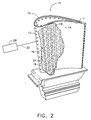
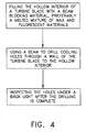
- the laser drilling method of the present invention is illustrated in FIG. 2 taken in conjunction with the flow chart illustrated in FIG. 4.
- the method includes the following steps; (a) filling the hollow interior 16 (cooling circuit 19) with a beam blocking material 24 having fluorescent material, (b) preferably using a laser 28 and a laser beam 30 to drill the holes 12 in the wall 15 through to the hollow interior 16, and (c) inspecting the holes after the drilling is complete under a black light 32 generated by a black light generator 34 as illustrated in FIG. 3.
- the hole detection and inspection in step (c) of the present invention can be done visually, by an operator using his eyes 38, or by electronic equipment and computers that use more sophisticated techniques to determine hole size and other parameters that are disclosed in the prior art.
- the beam blocking material preferably includes a wax material and step (a) preferably includes filling the hollow interior with a melted mixture of the wax and fluorescent materials.
- the wax material may be a pattern wax material suitable for use in making turbine blade investment casting molds and the fluorescent material may be a fluorescent penetrant several of which are commonly known and used in the art to detect cracks.
- One such wax material that was tested is SW-12 Pattern Wax from Kindt-Collins Inc. of Dayton, Ohio which was mixed with a fluorescent penetrant named HM604 DUBL-CHEK Penetrant from Sherwin Inc. of Southgate, California.
- An airflow check may be used thereafter as is commonly done in the art to check for proper airflow through the serpentine cooling circuit and cooling holes.
- the present invention also includes the various embodiments of the beam blocking material disclosed herein including a mixture of melted wax and fluorescent materials. After the inspection has been completed, the wax material may be removed by melting, evaporation, or burning.
Landscapes
- Physics & Mathematics (AREA)
- Health & Medical Sciences (AREA)
- Life Sciences & Earth Sciences (AREA)
- Chemical & Material Sciences (AREA)
- Analytical Chemistry (AREA)
- Biochemistry (AREA)
- General Health & Medical Sciences (AREA)
- General Physics & Mathematics (AREA)
- Immunology (AREA)
- Pathology (AREA)
- Engineering & Computer Science (AREA)
- Optics & Photonics (AREA)
- Plasma & Fusion (AREA)
- Mechanical Engineering (AREA)
- Spectroscopy & Molecular Physics (AREA)
- Turbine Rotor Nozzle Sealing (AREA)
- Investigating Materials By The Use Of Optical Means Adapted For Particular Applications (AREA)
Claims (5)
- Procédé pour former et inspecter des trous percés par un faisceau (12) dans une paroi (15) d'un article (10) avec un intérieur creux (16), ledit procédé comprenant :(a) le remplissage de l'intérieur creux (16) avec un matériau de blocage de faisceau (24) comportant un matériau fluorescent,(b) le perçage par un faisceau des trous (12) dans la paroi (15) jusqu'à l'intérieur creux (16), et(c) l'inspection des trous (12) sous une lumière noire (32).
- Procédé selon la revendication 1, dans lequel ladite étape de perçage par un faisceau comprend un perçage au laser (30).
- Procédé selon la revendication 2, dans lequel ledit matériau de blocage de faisceau (24) comprend un matériau en cire et l'étape (a) comprend le remplissage de l'intérieur creux (16) avec un mélange fondu des matériaux en cire et fluorescent.
- Procédé selon la revendication 3, dans lequel ledit matériau en cire est un matériau en cire à empreintes approprié pour être utilisé pour réaliser des moules de coulée à cire perdue pour des aubes de turbine (10).
- Procédé selon la revendication 4, dans lequel ledit matériau fluorescent est un agent pénétrant fluorescent.
Applications Claiming Priority (2)
| Application Number | Priority Date | Filing Date | Title |
|---|---|---|---|
| US78613297A | 1997-01-21 | 1997-01-21 | |
| US786132 | 1997-01-21 |
Publications (3)
| Publication Number | Publication Date |
|---|---|
| EP0854005A2 EP0854005A2 (fr) | 1998-07-22 |
| EP0854005A3 EP0854005A3 (fr) | 1998-07-29 |
| EP0854005B1 true EP0854005B1 (fr) | 2002-04-17 |
Family
ID=25137679
Family Applications (1)
| Application Number | Title | Priority Date | Filing Date |
|---|---|---|---|
| EP98300208A Expired - Lifetime EP0854005B1 (fr) | 1997-01-21 | 1998-01-13 | Procédé de perçage au moyen d'un faisceau d'énergie, ainsi que procédé de contrôle de perforations de ventilation |
Country Status (4)
| Country | Link |
|---|---|
| US (1) | US5773790A (fr) |
| EP (1) | EP0854005B1 (fr) |
| JP (1) | JP4097756B2 (fr) |
| DE (1) | DE69804870T2 (fr) |
Families Citing this family (42)
| Publication number | Priority date | Publication date | Assignee | Title |
|---|---|---|---|---|
| US6103993A (en) * | 1996-07-10 | 2000-08-15 | Mtu Motoren-Und Turbinen-Union Munchen Gmbh | Hollow rotor blade of columnar structure having a single crystal column in which a series of holes are laser drilled |
| US5914060A (en) * | 1998-09-29 | 1999-06-22 | United Technologies Corporation | Method of laser drilling an airfoil |
| US5928534A (en) * | 1998-09-29 | 1999-07-27 | United Technologies Corporation | Method for reducing void volumes in cavities for laser drilling |
| US6329633B1 (en) * | 1998-11-20 | 2001-12-11 | United Technologies Corporation | Method and material for processing a component for laser machining |
| US6251315B1 (en) * | 1998-11-20 | 2001-06-26 | United Technologies Corporation | Method for disposing a laser blocking material on the interior of an airfoil |
| US6150656A (en) * | 1998-12-10 | 2000-11-21 | United Technologies Corporation | Method of assembly and inspection for a gas turbine engine |
| US6339208B1 (en) * | 2000-01-19 | 2002-01-15 | General Electric Company | Method of forming cooling holes |
| US6441341B1 (en) | 2000-06-16 | 2002-08-27 | General Electric Company | Method of forming cooling holes in a ceramic matrix composite turbine components |
| US6909800B2 (en) * | 2000-12-15 | 2005-06-21 | United Technologies Corporation | Process and apparatus for locating coated cooling holes on turbine vanes |
| US6634858B2 (en) * | 2001-06-11 | 2003-10-21 | Alstom (Switzerland) Ltd | Gas turbine airfoil |
| US6547645B2 (en) | 2001-08-27 | 2003-04-15 | General Electric Company | Method and backer inserts for blocking backwall water jet strikes |
| EP1365039A1 (fr) * | 2002-05-24 | 2003-11-26 | ALSTOM (Switzerland) Ltd | Porcédé pour couvrir les orifices de refroidissement d'un composant d'une turbine à gaz |
| US20050248060A1 (en) * | 2002-06-28 | 2005-11-10 | 3M Innovative Properties Company | Manufacture of valve stems |
| DE60310168T2 (de) * | 2002-08-02 | 2007-09-13 | Alstom Technology Ltd. | Verfahren zum Schutz von Teilflächen eines Werkstücks |
| EP1416266B1 (fr) | 2002-11-04 | 2006-09-27 | Siemens Aktiengesellschaft | Procédé d' inspection de la structure de trous de passage d'un matériau |
| US7095495B2 (en) * | 2003-01-31 | 2006-08-22 | General Electric Company | Fluorescent inspection of airfoil cooling holes |
| GB0426780D0 (en) * | 2004-12-07 | 2005-01-12 | 3M Innovative Properties Co | Pressurized inhalation devices |
| GB0427281D0 (en) * | 2004-12-14 | 2005-01-12 | 3M Innovative Properties Co | Methods of providing medicinal metal components having through holes |
| GB0428169D0 (en) * | 2004-12-23 | 2005-01-26 | 3M Innovative Properties Co | Pressurized inhalation devices |
| US7333218B2 (en) * | 2005-06-28 | 2008-02-19 | United Technologies Corporation | Systems and methods for determining the location and angular orientation of a hole with an obstructed opening residing on a surface of an article |
| DE202007019098U1 (de) * | 2007-06-22 | 2010-08-12 | Automation W + R Gmbh | Anordnung zur optischen Überprüfung von einseitig offenen tunnelartigen Hohlräumen in Werkstücken, insbesondere von Kühlkanälen in Bremsscheiben |
| US7909507B2 (en) * | 2008-04-11 | 2011-03-22 | General Electric Company | Thermal inspection system and method |
| GB0914904D0 (en) * | 2009-08-27 | 2009-09-30 | Rolls Royce Plc | Inspection of holes |
| US8810644B2 (en) * | 2010-12-15 | 2014-08-19 | General Electric Company | Thermal inspection and machining systems and methods of use |
| DE102011121634B4 (de) | 2010-12-27 | 2019-08-14 | Ansaldo Energia Ip Uk Limited | Turbinenschaufel |
| DE202011109225U1 (de) | 2010-12-27 | 2012-03-05 | Alstom Technology Ltd. | Turbinenschaufel |
| CN102248306A (zh) * | 2011-04-02 | 2011-11-23 | 周明 | 一种激光钻孔高温合金材料燃气轮机叶片的装备和工艺方法 |
| CN102880116B (zh) * | 2012-08-27 | 2014-09-17 | 沈阳黎明航空发动机(集团)有限责任公司 | 一种用于激光加工多波群孔的数据采集及优化方法 |
| DE102014220523A1 (de) * | 2014-10-09 | 2016-04-14 | Siemens Aktiengesellschaft | Verfahren zum Herstellen von Durchgangsbohrungen mittels Laserstrahlung in einer Wandung eines Bauteils |
| DE102014220526A1 (de) * | 2014-10-09 | 2016-04-14 | Siemens Aktiengesellschaft | Verfahren zum Herstellen von Durchgangsbohrungen mittels Laserstrahlung in einer Wandung eines Bauteils |
| DE102015206984B4 (de) * | 2015-04-17 | 2019-05-09 | Fraunhofer-Gesellschaft zur Förderung der angewandten Forschung e.V. | Verfahren und Vorrichtung zur optischen Kontrolle von Kühlluftausnehmungen von Turbomaschinen |
| CN105290422B (zh) * | 2015-11-20 | 2017-05-10 | 沈阳黎明航空发动机(集团)有限责任公司 | 一种可调静子叶片的加工方法 |
| JP2018051764A (ja) * | 2016-09-26 | 2018-04-05 | エスアイアイ・プリンテック株式会社 | 噴射孔プレートの製造方法 |
| WO2019162464A1 (fr) | 2018-02-23 | 2019-08-29 | Avonisys Ag | Procédé d'usinage d'un alésage s'étendant à partir d'une paroi externe d'une pièce à travailler avec un faisceau laser guidé par jet de liquide |
| KR102291087B1 (ko) * | 2018-03-19 | 2021-08-18 | 두산중공업 주식회사 | 보호장치 |
| US10551327B2 (en) | 2018-04-11 | 2020-02-04 | General Electric Company | Cooling hole inspection system |
| DE102018211288A1 (de) * | 2018-07-09 | 2020-01-09 | Siemens Aktiengesellschaft | Vorrichtung und Verfahren zur Oberflächenanalyse von Bauteilen mit Kühlfluidöffnungen |
| US10895448B2 (en) | 2019-04-09 | 2021-01-19 | General Electric Company | System and method for collecting measurement data of shaped cooling holes of CMC components |
| US11413703B2 (en) | 2019-05-22 | 2022-08-16 | General Electric Company | Method of forming cooling holes |
| US11492913B2 (en) | 2020-07-21 | 2022-11-08 | General Electric Company | Cooling hole inspection system |
| US11885688B2 (en) | 2020-07-21 | 2024-01-30 | General Electric Company | Method and system for inspecting cooling holes of a turbine engine component |
| CN112304625B (zh) * | 2020-10-21 | 2022-07-15 | 江苏江航智飞机发动机部件研究院有限公司 | 一种用于飞机发动机涡轮叶片的检测装置 |
Family Cites Families (23)
| Publication number | Priority date | Publication date | Assignee | Title |
|---|---|---|---|---|
| US3607333A (en) * | 1969-02-17 | 1971-09-21 | James R Alburger | Developers for inspection penetrants employing fusible waxes |
| US3624397A (en) * | 1969-10-01 | 1971-11-30 | Trw Inc | Radiographic method for the detection of residual core material comprising the use of radiographically detectable powder |
| US3806252A (en) * | 1972-07-10 | 1974-04-23 | Eastman Kodak Co | Hole measurer |
| US3904545A (en) * | 1973-02-05 | 1975-09-09 | Rockwell International Corp | Liquid dye penetrant composition containing a wax |
| US3880790A (en) * | 1973-05-14 | 1975-04-29 | Petrolite Corp | Investment casting wax composition |
| US4377492A (en) * | 1980-09-08 | 1983-03-22 | Purex Corporation | Post emulsifiable fluorescent penetrant |
| US4447152A (en) * | 1981-12-24 | 1984-05-08 | Ibm Corp. | Method and apparatus for detecting defects in apertured plates |
| US4644162A (en) * | 1984-09-20 | 1987-02-17 | General Electric Company | Cooling hole inspection |
| JPH0660878B2 (ja) * | 1987-06-25 | 1994-08-10 | 株式会社日立製作所 | 多層プリント基板におけるスルーホールボイド検査方法とその装置 |
| US5011626A (en) * | 1988-06-13 | 1991-04-30 | Rolls-Royce Inc. | Barrier materials for laser drilling |
| US4873414A (en) * | 1988-06-13 | 1989-10-10 | Rolls Royce Inc. | Laser drilling of components |
| FR2636423B1 (fr) * | 1988-09-15 | 1990-11-30 | Snecma | Controle optique de micropercages d'aubes de turbine |
| GB8921040D0 (en) * | 1989-09-16 | 1989-11-01 | Rolls Royce Plc | Laser barrier material |
| US5140127A (en) * | 1989-09-20 | 1992-08-18 | Rolls-Royce Plc | Laser barrier material |
| GB2243320B (en) * | 1990-04-26 | 1993-08-25 | Ae Turbine Components | Laser drilling |
| JPH0441090A (ja) * | 1990-06-06 | 1992-02-12 | Toshiba Corp | レーザ穴あけ方法 |
| GB2249279B (en) * | 1990-10-17 | 1994-01-05 | Rolls Royce Plc | Improvements in or relating to drilling turbine blades |
| JPH04165057A (ja) * | 1990-10-29 | 1992-06-10 | Mitsubishi Heavy Ind Ltd | マスク材の検出方法 |
| US5111046A (en) * | 1991-03-18 | 1992-05-05 | General Electric Company | Apparatus and method for inspecting cooling holes |
| US5247766A (en) * | 1992-01-31 | 1993-09-28 | Kildea Robert J | Process for improving cooling hole flow control |
| US5286947A (en) * | 1992-09-08 | 1994-02-15 | General Electric Company | Apparatus and method for monitoring material removal from a workpiece |
| US5517310A (en) * | 1994-06-30 | 1996-05-14 | Solar Turbines Incorporated | Method and apparatus for obtaining and analyzing an image of a elongate slot |
| US5614114A (en) * | 1994-07-18 | 1997-03-25 | Electro Scientific Industries, Inc. | Laser system and method for plating vias |
-
1997
- 1997-09-09 US US08/925,906 patent/US5773790A/en not_active Expired - Lifetime
-
1998
- 1998-01-13 DE DE69804870T patent/DE69804870T2/de not_active Expired - Lifetime
- 1998-01-13 EP EP98300208A patent/EP0854005B1/fr not_active Expired - Lifetime
- 1998-01-20 JP JP00822598A patent/JP4097756B2/ja not_active Expired - Fee Related
Also Published As
| Publication number | Publication date |
|---|---|
| EP0854005A3 (fr) | 1998-07-29 |
| JPH10317909A (ja) | 1998-12-02 |
| DE69804870T2 (de) | 2002-11-21 |
| DE69804870D1 (de) | 2002-05-23 |
| EP0854005A2 (fr) | 1998-07-22 |
| US5773790A (en) | 1998-06-30 |
| JP4097756B2 (ja) | 2008-06-11 |
Similar Documents
| Publication | Publication Date | Title |
|---|---|---|
| US5773790A (en) | Beam blocking material and method for beam drilling and inspecting cooling holes | |
| US5111046A (en) | Apparatus and method for inspecting cooling holes | |
| US9310312B2 (en) | Apparatus and method for automatic inspection of through-holes of a component | |
| US9274009B2 (en) | Apparatus and method for measurement of the film cooling effect produced by air cooled gas turbine components | |
| GB2164746A (en) | Cooling hole inspection | |
| JP4572412B2 (ja) | 経時プラズマ光スペクトル解析を用いたレーザー衝撃ピーニングの監視及び制御方法 | |
| JP2007009908A (ja) | 1つまたは複数の孔の位置および角度方向の特定方法および特定装置 | |
| US7651261B2 (en) | System and method for thermal inspection of parts | |
| US8699037B2 (en) | Hole inspection | |
| EP0943916A2 (fr) | Procédé et appareil de contrôle des objets | |
| JP2007279046A (ja) | 検査システムおよびその方法 | |
| US20060157456A1 (en) | Automated adaptive machining of obstructed passages | |
| US10119863B2 (en) | Flash thermography photobox | |
| EP1726943A1 (fr) | Procédé et appareil de thermographie | |
| EP2354783A1 (fr) | Système d'inspection thermique et procédé incorporant un écoulement externe | |
| JPH03170005A (ja) | タービン翼の微細孔の光学検査 | |
| JP2007237295A (ja) | 穿孔プロセスパラメータをモニターし穿孔動作を制御するためのシステム及び方法 | |
| JP2019002788A (ja) | 金属加工面の検査方法、金属加工面の検査装置 | |
| JP2004264305A (ja) | 内部渦電流探傷検査 | |
| US7075083B2 (en) | Method for examining the structure of through-holes of a component | |
| US6963396B2 (en) | Light hole inspection system for engine component | |
| EP0713745A1 (fr) | Méthode et dispositif pour la fabrication de pièces ajourées | |
| JPH09141424A (ja) | 切断火口の検査装置及び検査方法及び切断装置 | |
| US20250389679A1 (en) | Automated method of evaluating candle burn performance | |
| JP2002309904A (ja) | タービン静翼インサート部材の検査装置及び検査方法 |
Legal Events
| Date | Code | Title | Description |
|---|---|---|---|
| PUAI | Public reference made under article 153(3) epc to a published international application that has entered the european phase |
Free format text: ORIGINAL CODE: 0009012 |
|
| PUAL | Search report despatched |
Free format text: ORIGINAL CODE: 0009013 |
|
| AK | Designated contracting states |
Kind code of ref document: A2 Designated state(s): DE FR GB |
|
| AX | Request for extension of the european patent |
Free format text: AL;LT;LV;MK;RO;SI |
|
| AK | Designated contracting states |
Kind code of ref document: A3 Designated state(s): AT BE CH DE DK ES FI FR GB GR IE IT LI LU MC NL PT SE |
|
| AX | Request for extension of the european patent |
Free format text: AL;LT;LV;MK;RO;SI |
|
| 17P | Request for examination filed |
Effective date: 19990129 |
|
| AKX | Designation fees paid |
Free format text: DE FR GB |
|
| RBV | Designated contracting states (corrected) |
Designated state(s): DE FR GB |
|
| RTI1 | Title (correction) |
Free format text: METHOD FOR BEAM DRILLING AND INSPECTING COOLING HOLES |
|
| GRAG | Despatch of communication of intention to grant |
Free format text: ORIGINAL CODE: EPIDOS AGRA |
|
| 17Q | First examination report despatched |
Effective date: 20010530 |
|
| GRAG | Despatch of communication of intention to grant |
Free format text: ORIGINAL CODE: EPIDOS AGRA |
|
| GRAH | Despatch of communication of intention to grant a patent |
Free format text: ORIGINAL CODE: EPIDOS IGRA |
|
| GRAH | Despatch of communication of intention to grant a patent |
Free format text: ORIGINAL CODE: EPIDOS IGRA |
|
| REG | Reference to a national code |
Ref country code: GB Ref legal event code: IF02 |
|
| GRAA | (expected) grant |
Free format text: ORIGINAL CODE: 0009210 |
|
| AK | Designated contracting states |
Kind code of ref document: B1 Designated state(s): DE FR GB |
|
| REF | Corresponds to: |
Ref document number: 69804870 Country of ref document: DE Date of ref document: 20020523 |
|
| ET | Fr: translation filed | ||
| PLBE | No opposition filed within time limit |
Free format text: ORIGINAL CODE: 0009261 |
|
| STAA | Information on the status of an ep patent application or granted ep patent |
Free format text: STATUS: NO OPPOSITION FILED WITHIN TIME LIMIT |
|
| 26N | No opposition filed |
Effective date: 20030120 |
|
| REG | Reference to a national code |
Ref country code: FR Ref legal event code: PLFP Year of fee payment: 19 |
|
| PGFP | Annual fee paid to national office [announced via postgrant information from national office to epo] |
Ref country code: DE Payment date: 20160127 Year of fee payment: 19 |
|
| PGFP | Annual fee paid to national office [announced via postgrant information from national office to epo] |
Ref country code: FR Payment date: 20160126 Year of fee payment: 19 Ref country code: GB Payment date: 20160127 Year of fee payment: 19 |
|
| REG | Reference to a national code |
Ref country code: DE Ref legal event code: R119 Ref document number: 69804870 Country of ref document: DE |
|
| GBPC | Gb: european patent ceased through non-payment of renewal fee |
Effective date: 20170113 |
|
| REG | Reference to a national code |
Ref country code: FR Ref legal event code: ST Effective date: 20170929 |
|
| PG25 | Lapsed in a contracting state [announced via postgrant information from national office to epo] |
Ref country code: FR Free format text: LAPSE BECAUSE OF NON-PAYMENT OF DUE FEES Effective date: 20170131 |
|
| PG25 | Lapsed in a contracting state [announced via postgrant information from national office to epo] |
Ref country code: DE Free format text: LAPSE BECAUSE OF NON-PAYMENT OF DUE FEES Effective date: 20170801 Ref country code: GB Free format text: LAPSE BECAUSE OF NON-PAYMENT OF DUE FEES Effective date: 20170113 |