EP0854224A2 - Elément d'emballage pour le transport d'une machine à laver domestique - Google Patents
Elément d'emballage pour le transport d'une machine à laver domestique Download PDFInfo
- Publication number
- EP0854224A2 EP0854224A2 EP97122180A EP97122180A EP0854224A2 EP 0854224 A2 EP0854224 A2 EP 0854224A2 EP 97122180 A EP97122180 A EP 97122180A EP 97122180 A EP97122180 A EP 97122180A EP 0854224 A2 EP0854224 A2 EP 0854224A2
- Authority
- EP
- European Patent Office
- Prior art keywords
- washing machine
- loading door
- transport packaging
- packaging element
- element according
- Prior art date
- Legal status (The legal status is an assumption and is not a legal conclusion. Google has not performed a legal analysis and makes no representation as to the accuracy of the status listed.)
- Granted
Links
Images
Classifications
-
- D—TEXTILES; PAPER
- D06—TREATMENT OF TEXTILES OR THE LIKE; LAUNDERING; FLEXIBLE MATERIALS NOT OTHERWISE PROVIDED FOR
- D06F—LAUNDERING, DRYING, IRONING, PRESSING OR FOLDING TEXTILE ARTICLES
- D06F39/00—Details of washing machines not specific to a single type of machines covered by groups D06F9/00 - D06F27/00
- D06F39/001—Arrangements for transporting, moving, or setting washing machines; Protective arrangements for use during transport
Definitions
- the present invention refers to a transport packaging element that is capable of preventing the suspended washing assembly of the washing machine from undergoing any displacement with respect to the outer machine casing during handling and transport of the same machine from the end of the production line at the factory through to the installation site thereof.
- a washing machine is contituted by a series of various sub-assemblies, one of which, a stationary one, comprises the load-bearing structure and the outer casing of the machine and another one, generally termed “washing assembly”, “suspended assembly” or even “oscillating assembly” in the art, comprises in particular the rotating drum accomodating the washload, along with the driving motor thereof.
- the door that closes the aperture provided to load the clothes into the rotating drum is hinged on to the outer casing.
- the washing assembly is supported elastically by the stationary subassembly of the washing machine since it is subject to continuous, repeated oscillations during the operation of the machine.
- the transport packaging must therefore include means that are capable of locking the washing assembly in position during all handling and transport operations that the machine undergoes starting from the end of the production line through to the installation site thereof at the user's home, in view of preventing any damage from occurring, such as for example due to said washing assembly impinging against the outer casing.
- a further purpose of the present invention is to avoid creating particular materials management problems at the factory where the washing machines are manufactured, since the above cited element is very simple in its construction.
- Still a further purpose of the present invention is to make it possible for said transport packaging element to be repeatedly reused, even several times, at said manufacturing factory owing to the fact that, upon being removed from a washing machine at the installation site thereof, said element can be most conveniently returend to the manufacturing factory, as this will be better explained further on.
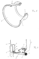
- the first embodiment of the afore cited transport packaging element adapted to lock in place the washing or suspended assembly of a household washing machine essentially consists of a single piece, which is generally indicated at 1 in the drawings and comprises two coaxially arranged portions in the shape of toroidal rings 3 and 4, along with an intermediate portion 2 which serves the purpose of flexibly connecting said rings 3 and 4 to each other, in the form of a frustoconical surface (see Figure 1).
- the toroidal rings 3 and 4 are made of an elastically deformable material, such as for instance closed-cell polyurethane foam having a density comprised between 75 and 100 kg/cu.m or elastomeric rubber.
- the above mentioned flexible portion 2 may for instance be made of rubberized fabric having an adequately sized thickness, eg. in the region of some tenths of a millimeter.
- One among the possible methods that can be used to manufacture the element 1 includes the phase in which a plane length of rubberized cloth in the shape of a sector of a part of a circle ring which is generally known to constitute the development on a plane of a frustoconical surface.
- the polyurethane foamd is moulded, ie.
- the two free ends of the first and the second bead, as well as the free edges of the rubberized cloth that are a part of the above mentioned semi-processed item, are connected to each other.
- This last phase of the manufacturing process can be carried out with the utilization of any appropriate technique that is known in the art for joining synthetic and similar materials, eg. by means of adhesive bonding or ultrasonic welding, so that no further explanation is felt to be necessary here.
- the so obtained element 1 according to the invention is a part that, as this has already been stated earlier, has a frustoconocal shape in which the thicker toroidal ring 3 is the circumferential edge of the smaller base and the thinner toroidal ring 4 is the circumferential edge of the larger base (see Figure 1).
- the element 1 is in this way ready for being mounted in a washing machine with a front-loading door as the latter is being packaged for transport after its assembly and final inspection and testing at the manufacturing factory.
- the thinner ring 4 remains elastically squeezed between the outer flange 9 of the same door 6 (to which the system, not shown in the Figure, for hinging the door on to the outer casing 12 of the washing machine is attached) and the circumferential edge 10 of the bellows-like gasket 11 that is attached to the front surface of the same outer casing 12.
- the intermediate flexible portion 2 of the element 1 is able to extend along said bellows-like gasket 11, since it has the possibility of adapting itself to both the shape and the dimensions of the latter.
- Test carried out at the factory by the Applicant on a package arrangement inclusive of the above mentioned element 1 have demonstrated that such an element is actually capable of ensuring an effective protection against shocks to both the washing assembly and the outer casing of the machine during handling and transport of the washing machine up to its final installation site.
- the thicker ring 3 keeps the drum 8 separated from the loading door 6, while the thinner ring 4 keeps the same door 6 separated from the bellows-like gasket 11 and, as a result, from the outer casing 12.
- the elastic deformability, the low weight, the absence of metal parts are as many features that make it much easier and convenient for the element 1 to be both assembled at the factory where the washing machines are manufactured and, of course, removed from the washing machine (so as to enable the latter to start operating regularly) at the site of installation thereof, even by a person that does not possess any particular dexterity or skill in this connection, and without any tool being actually required. All it takes to do that, in fact, is to open the loading door 6, pulling with the hand the thinner toroidal ring 4, which is situated in a conveniently exposed position on the front surface of the casing 12, outwardly in the direction shown by the arrow F1 or, practically, according to the axis of the door 6.
- the flexible connecting portion 2 between the two rings will in this way cause the thicker ring 3, which by this time is no longer pressed by the dome-shaped portion of the door 6, to separate from the edge 7 of the loading aperture of the washing drum 8 (see Figure 2).
- a variant, not described in the following, but largely similar to the afore illustrated embodiment of the invention and capable of being used in washing machines having a quadrilateral loading door on their top, will feature the shape of a truncated pyramid, with toroidal rings that have a substantially square development. Furthermore, if required by particular needs, the toroidal rings that are a part of the elemnt 1 can be provided in a greater number than two.
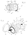
- the second embodiment of a transport packaging element capable of locking in place the washing assembly of a household washing machine comprises, as this is illustrated in Figure 3, a first portion constituted by a frustoconical hollow body 20, and a second portion constituted by a circular toroidal ring 30 having a substantially circular cross-section. Both portions 20 and 30 are made of a synthetic flexible material, such as for instance polypropylene without additives.
- the body 20 has a larger base in the shape of a flanged circular ring 21 and a smaller base 22 in the shape of a circular ring with three radial appendixes 23 extending on a transversal plane with respect to the axis X of the frustoconical body 20 and spaced by an angle of 120° from each other.
- Said bases 21 and 22 of the body 20 are parallel to and at a distance L from each other.
- the frustoconical side surface 24 of the body 20 is constituted by an array of strips 25 extending in an inclined manner with respect to the axis X and terminating at the bases 2 and 3, respectively, said strips being further separated from each other by interruptions 6 extending in the same way as the strips.
- the toroidal ring 30 (which is shown only partially in Figure 3 for reasons of greater clearness) is provided with a slit 31 extending along the inner circumference thereof so as to fit in the flanged portion of the larger base 21 of the same frustoconical body 20.
- Figure 4 illustrates the manner in which the above described packaging element is mounted in a household washing machine with front loading door at the factory in which said machine is manufactured, during the packaging operations that are carried out after the assembly and the final inspection thereof, to the purpose of making it sure for the washing assembly of the same machine to be safely locked in place until the machine reaches its site of installation.
- the washing assembly of a machine of the above mentioned kind comprises a rotating washing drum 40 formed by a front flange 41 with a central aperture 42 for loading the clothes thereinto, a rear flange 43 and a substantially cylindrical side surface 44.
- the clothes loading aperture 42 is delimited by the inner circular protruding edge 45 of the front flange 41.
- the rear flange 43 which is situated at a distance D from the front flange 41, is provided with a central trilobate press-stamped impression 46.
- the machine also comprises a porthole-like loading door 47 that is hinged on to the front surface of the outer casing (not shown) of the machine in a generally known manner and comprises a dome-shaped portion 48 associated to the loading aperture 42 of the drum 40.
- the element for locking in place the washing assembly is introduced in the drum 40 through the eprture 42 by pushing it in the direction shown by the arrow F3 up to the point in which the radial appendixes 23 of the smaller base 33 of the frustoconical body 20 get into position between the lobes of the deep-drawn impression 46 of the rear wall 43, thereby preventing the hollow body 20 from falling inside the drum 40.
- the toroidal ring 30 abuts against the protruding edge 45 of the front flange 41, which defines the aperture 42 of the drum 40.
- the length of the hollow body 20 undergoes a certain reduction from the initial value L thereof (see further above) down to the final value D, since the frustoconical surface 24 thereof undergoes an elastic deformation (torsion).
- the loading door 47 is shut (as indicated by the arrow F2 in Figure 4), so that the dome-shaped portion 48 thereof is brought to intefere with the toroidal ring 30, thereby causing the latter to undergo an elastic deformation owing to the pressure that is exerted against the afore mentioned protruding edge 45.
- the toroidal ring 30 remains in this way retained between the drum 40 and the door 47 and is no longer able to come off.
- the smaller base 22 of the frustoconical body 20 remains pressed against the rear flange 43 of the drum 40 (as indicated by the arrow F3) since the radial appendixes 23 thereof are retained by the trilobate deep-drawn impression 46 provided in the same flange 43.
- this embodiment of the present invention thanks to the elastic deformability of the parts involved, the low weight, the absence of metal parts, makes it particularly easy and convenient for the element to be not only mounted in the washing machine, as described above, at the factory, but also to be removed from the washing machine after the latter reaches the installation site thereof.
- Such a removal can in fact be carried out, without any use of tools, even by a person who does not possess any particular manual dexterity. All this person has in fact to do in this connection is to open the porthole-like door 47, remove the toroidal ring 30 from the protruding edge 45 of the drum 40 by separating it from the flange of the larger base 21 of the frustoconical body 20. The latter can at this point be removed from the drum 40 through the aperture 42 by pulling it in the opposite direction with respect to the one indicated by the arrow F3 (see Figure 4).
- the two parts constituting the washing assembly locking arrangement according to the present invention ie. the frustoconical body 20 and the toroidal ring 30, have been so removed from the washing machine, it is most easy for the purchaser to return them to the factory, or the shop, as this has already been described above.
- this embodiment of the present invention is open to variants, in particular in the case of top-loading washing machines. It will be further appreciated that, further to these variants, a number of other embodiments may be developed by those skilled in the art on the basis of the afore described innovative principles, which therefore do not depart from the scope of the present invention.
Landscapes
- Engineering & Computer Science (AREA)
- Textile Engineering (AREA)
- Main Body Construction Of Washing Machines And Laundry Dryers (AREA)
- Packaging Of Machine Parts And Wound Products (AREA)
- Containers And Plastic Fillers For Packaging (AREA)
- Buffer Packaging (AREA)
Applications Claiming Priority (2)
| Application Number | Priority Date | Filing Date | Title |
|---|---|---|---|
| IT97PN000001 IT243406Y1 (it) | 1997-01-17 | 1997-01-17 | Elemento dell'imballo di trasporto di una lavatrice domestica |
| ITPN970001U | 1997-01-17 |
Publications (3)
| Publication Number | Publication Date |
|---|---|
| EP0854224A2 true EP0854224A2 (fr) | 1998-07-22 |
| EP0854224A3 EP0854224A3 (fr) | 1998-12-16 |
| EP0854224B1 EP0854224B1 (fr) | 2002-03-20 |
Family
ID=11395206
Family Applications (1)
| Application Number | Title | Priority Date | Filing Date |
|---|---|---|---|
| EP19970122180 Expired - Lifetime EP0854224B1 (fr) | 1997-01-17 | 1997-12-16 | Elément d'emballage pour le transport d'une machine à laver domestique |
Country Status (4)
| Country | Link |
|---|---|
| EP (1) | EP0854224B1 (fr) |
| DE (1) | DE69711165T2 (fr) |
| ES (1) | ES2174172T3 (fr) |
| IT (1) | IT243406Y1 (fr) |
Cited By (2)
| Publication number | Priority date | Publication date | Assignee | Title |
|---|---|---|---|---|
| WO2007141329A3 (fr) * | 2006-06-09 | 2008-02-14 | Arcelik As | Appareil électroménager |
| CN104797754A (zh) * | 2012-11-22 | 2015-07-22 | Bsh家用电器有限公司 | 用于洗衣机的运输紧固系统以及所配属的洗衣机 |
Families Citing this family (1)
| Publication number | Priority date | Publication date | Assignee | Title |
|---|---|---|---|---|
| CN111155277A (zh) * | 2018-10-22 | 2020-05-15 | 青岛海尔滚筒洗衣机有限公司 | 一种运输减震装置、衣物处理设备及控制方法 |
Family Cites Families (3)
| Publication number | Priority date | Publication date | Assignee | Title |
|---|---|---|---|---|
| US3187887A (en) * | 1962-11-14 | 1965-06-08 | Iden Mfg Co Inc | Packing for washing machines |
| US3620365A (en) * | 1969-06-05 | 1971-11-16 | Maurice W Elwell | Washing machine packing brace |
| US4366902A (en) * | 1981-04-30 | 1983-01-04 | Whirlpool Corporation | Shipping system for automatic washer |
-
1997
- 1997-01-17 IT IT97PN000001 patent/IT243406Y1/it active
- 1997-12-16 ES ES97122180T patent/ES2174172T3/es not_active Expired - Lifetime
- 1997-12-16 DE DE1997611165 patent/DE69711165T2/de not_active Expired - Fee Related
- 1997-12-16 EP EP19970122180 patent/EP0854224B1/fr not_active Expired - Lifetime
Cited By (3)
| Publication number | Priority date | Publication date | Assignee | Title |
|---|---|---|---|---|
| WO2007141329A3 (fr) * | 2006-06-09 | 2008-02-14 | Arcelik As | Appareil électroménager |
| CN104797754A (zh) * | 2012-11-22 | 2015-07-22 | Bsh家用电器有限公司 | 用于洗衣机的运输紧固系统以及所配属的洗衣机 |
| CN104797754B (zh) * | 2012-11-22 | 2017-04-26 | Bsh家用电器有限公司 | 用于洗衣机的运输紧固系统以及所配属的洗衣机 |
Also Published As
| Publication number | Publication date |
|---|---|
| EP0854224B1 (fr) | 2002-03-20 |
| EP0854224A3 (fr) | 1998-12-16 |
| IT243406Y1 (it) | 2002-03-04 |
| ITPN970001U1 (it) | 1998-07-17 |
| DE69711165T2 (de) | 2002-08-14 |
| DE69711165D1 (de) | 2002-04-25 |
| ES2174172T3 (es) | 2002-11-01 |
Similar Documents
| Publication | Publication Date | Title |
|---|---|---|
| JP5180253B2 (ja) | ドラム | |
| US5433091A (en) | Plastic drum for clothes washing machines | |
| US6212792B1 (en) | Basket and method of use | |
| JP5065485B2 (ja) | 洗濯機のためのバスケットアセンブリ | |
| WO1995033881A2 (fr) | Protection pour sous-vetements | |
| US20070084254A1 (en) | Combination washer/dryer laundry basket | |
| EP0854224B1 (fr) | Elément d'emballage pour le transport d'une machine à laver domestique | |
| US4366902A (en) | Shipping system for automatic washer | |
| BE1007858A3 (nl) | Elastische dichtingsring voor was- en droogmachines en gelijkaardige machines en machine voorzien van dergelijke dichtingsring. | |
| CA2128768A1 (fr) | Agitateur de lessiveuse automatique a ailette amelioree d'entrainement des vetements | |
| US20060150688A1 (en) | Drum of drum type washing machine | |
| US3058507A (en) | Linemen's tool bucket | |
| KR102711550B1 (ko) | 세탁기 및 그 제조 방법 | |
| US20090120139A1 (en) | A Laundry Drum | |
| EP0725179A1 (fr) | Dispositif pour éviter le balourd du tambour d'une machine à laver | |
| EP0926290B1 (fr) | Machine à laver avec dispositif d'ancrage de la cuve | |
| EP0933463A1 (fr) | Dispositif pour fixer un amortisseur à la cuve d'une machine à laver | |
| EP0736117B1 (fr) | Amelioration de la cuve de lavage d'une machine a laver le linge | |
| EP3899124B1 (fr) | Machine à laver/sécher le linge ayant une cuve à résistance mécanique améliorée | |
| EP3957790B1 (fr) | Machine à laver ayant une cuve à nervures | |
| JP5644079B2 (ja) | 金属製物干し具 | |
| US20170145622A1 (en) | Closure panel and laundry treating appliance with same | |
| US4085532A (en) | Embroidery hoops | |
| CN1227617A (zh) | 多用途夹持装置 | |
| JP2000135396A (ja) | ドラム式洗濯脱水機 |
Legal Events
| Date | Code | Title | Description |
|---|---|---|---|
| PUAI | Public reference made under article 153(3) epc to a published international application that has entered the european phase |
Free format text: ORIGINAL CODE: 0009012 |
|
| AK | Designated contracting states |
Kind code of ref document: A2 Designated state(s): DE ES FR GB IT |
|
| AX | Request for extension of the european patent |
Free format text: AL;LT;LV;MK;RO;SI |
|
| PUAL | Search report despatched |
Free format text: ORIGINAL CODE: 0009013 |
|
| AK | Designated contracting states |
Kind code of ref document: A3 Designated state(s): AT BE CH DE DK ES FI FR GB GR IE IT LI LU MC NL PT SE |
|
| AX | Request for extension of the european patent |
Free format text: AL;LT;LV;MK;RO;SI |
|
| 17P | Request for examination filed |
Effective date: 19990527 |
|
| AKX | Designation fees paid |
Free format text: DE ES FR GB IT |
|
| 17Q | First examination report despatched |
Effective date: 20001227 |
|
| GRAG | Despatch of communication of intention to grant |
Free format text: ORIGINAL CODE: EPIDOS AGRA |
|
| GRAG | Despatch of communication of intention to grant |
Free format text: ORIGINAL CODE: EPIDOS AGRA |
|
| GRAH | Despatch of communication of intention to grant a patent |
Free format text: ORIGINAL CODE: EPIDOS IGRA |
|
| GRAH | Despatch of communication of intention to grant a patent |
Free format text: ORIGINAL CODE: EPIDOS IGRA |
|
| REG | Reference to a national code |
Ref country code: GB Ref legal event code: IF02 |
|
| GRAA | (expected) grant |
Free format text: ORIGINAL CODE: 0009210 |
|
| AK | Designated contracting states |
Kind code of ref document: B1 Designated state(s): DE ES FR GB IT |
|
| REF | Corresponds to: |
Ref document number: 69711165 Country of ref document: DE Date of ref document: 20020425 |
|
| ET | Fr: translation filed | ||
| REG | Reference to a national code |
Ref country code: ES Ref legal event code: FG2A Ref document number: 2174172 Country of ref document: ES Kind code of ref document: T3 |
|
| PLBE | No opposition filed within time limit |
Free format text: ORIGINAL CODE: 0009261 |
|
| STAA | Information on the status of an ep patent application or granted ep patent |
Free format text: STATUS: NO OPPOSITION FILED WITHIN TIME LIMIT |
|
| 26N | No opposition filed |
Effective date: 20021223 |
|
| PGFP | Annual fee paid to national office [announced via postgrant information from national office to epo] |
Ref country code: ES Payment date: 20081211 Year of fee payment: 12 |
|
| PGFP | Annual fee paid to national office [announced via postgrant information from national office to epo] |
Ref country code: IT Payment date: 20081204 Year of fee payment: 12 |
|
| PGFP | Annual fee paid to national office [announced via postgrant information from national office to epo] |
Ref country code: FR Payment date: 20081110 Year of fee payment: 12 |
|
| PGFP | Annual fee paid to national office [announced via postgrant information from national office to epo] |
Ref country code: DE Payment date: 20081128 Year of fee payment: 12 |
|
| PGFP | Annual fee paid to national office [announced via postgrant information from national office to epo] |
Ref country code: GB Payment date: 20081120 Year of fee payment: 12 |
|
| GBPC | Gb: european patent ceased through non-payment of renewal fee |
Effective date: 20091216 |
|
| REG | Reference to a national code |
Ref country code: FR Ref legal event code: ST Effective date: 20100831 |
|
| PG25 | Lapsed in a contracting state [announced via postgrant information from national office to epo] |
Ref country code: FR Free format text: LAPSE BECAUSE OF NON-PAYMENT OF DUE FEES Effective date: 20091231 |
|
| PG25 | Lapsed in a contracting state [announced via postgrant information from national office to epo] |
Ref country code: DE Free format text: LAPSE BECAUSE OF NON-PAYMENT OF DUE FEES Effective date: 20100701 |
|
| PG25 | Lapsed in a contracting state [announced via postgrant information from national office to epo] |
Ref country code: GB Free format text: LAPSE BECAUSE OF NON-PAYMENT OF DUE FEES Effective date: 20091216 |
|
| PG25 | Lapsed in a contracting state [announced via postgrant information from national office to epo] |
Ref country code: IT Free format text: LAPSE BECAUSE OF NON-PAYMENT OF DUE FEES Effective date: 20091216 |
|
| REG | Reference to a national code |
Ref country code: ES Ref legal event code: FD2A Effective date: 20110408 |
|
| PG25 | Lapsed in a contracting state [announced via postgrant information from national office to epo] |
Ref country code: ES Free format text: LAPSE BECAUSE OF NON-PAYMENT OF DUE FEES Effective date: 20110324 |
|
| PG25 | Lapsed in a contracting state [announced via postgrant information from national office to epo] |
Ref country code: ES Free format text: LAPSE BECAUSE OF NON-PAYMENT OF DUE FEES Effective date: 20091217 |