EP0854274A1 - Filtre à particules - Google Patents
Filtre à particules Download PDFInfo
- Publication number
- EP0854274A1 EP0854274A1 EP97121164A EP97121164A EP0854274A1 EP 0854274 A1 EP0854274 A1 EP 0854274A1 EP 97121164 A EP97121164 A EP 97121164A EP 97121164 A EP97121164 A EP 97121164A EP 0854274 A1 EP0854274 A1 EP 0854274A1
- Authority
- EP
- European Patent Office
- Prior art keywords
- filter
- particle filter
- flow
- resistance
- flow resistance
- Prior art date
- Legal status (The legal status is an assumption and is not a legal conclusion. Google has not performed a legal analysis and makes no representation as to the accuracy of the status listed.)
- Granted
Links
Images
Classifications
-
- F—MECHANICAL ENGINEERING; LIGHTING; HEATING; WEAPONS; BLASTING
- F01—MACHINES OR ENGINES IN GENERAL; ENGINE PLANTS IN GENERAL; STEAM ENGINES
- F01N—GAS-FLOW SILENCERS OR EXHAUST APPARATUS FOR MACHINES OR ENGINES IN GENERAL; GAS-FLOW SILENCERS OR EXHAUST APPARATUS FOR INTERNAL-COMBUSTION ENGINES
- F01N3/00—Exhaust or silencing apparatus having means for purifying, rendering innocuous, or otherwise treating exhaust
- F01N3/02—Exhaust or silencing apparatus having means for purifying, rendering innocuous, or otherwise treating exhaust for cooling, or for removing solid constituents of, exhaust
- F01N3/021—Exhaust or silencing apparatus having means for purifying, rendering innocuous, or otherwise treating exhaust for cooling, or for removing solid constituents of, exhaust by means of filters
- F01N3/023—Exhaust or silencing apparatus having means for purifying, rendering innocuous, or otherwise treating exhaust for cooling, or for removing solid constituents of, exhaust by means of filters using means for regenerating the filters, e.g. by burning trapped particles
Definitions
- the invention relates to a particle filter in the exhaust gas flow of a diesel engine is arranged and a method for complete Regenerate it.
- Particle filters are used to separate soot particles from the exhaust gas of diesel engines. With increasing thickness of the particle coating the exhaust gas pressure in front of the particle filter increases. Is a certain one Pressure level is reached, the particle filter is burned off regenerates the particle coating. This usually happens by exhaust gas of certain pressure and temperature, that from the diesel engine and one in the main stream of the Exhaust pipe arranged burner is supplied.
- the invention has for its object to provide a particle filter the particle coating completely burned off with each regeneration becomes.
- ⁇ o is meaningless and generally. also not measurable, since even a very low initial load can significantly increase the filter resistance.
- the pressure loss ⁇ o in the pure state of a filter medium or a filter constructed with it can therefore only be determined when the filter flows through with particle-free measuring gas.
- a partially regenerated particle filter leads to a shortening of the Loading phase and thereby to an undesirable increase the regeneration cycles and the possible overloading of the not completely regenerated filter surfaces with the risk of destruction in one of the following regenerations.
- the particle filter depending of operating parameters by burning off the soot particles is regenerable, complete regeneration is achieved by that the load-independent flow resistance of a Filter unit over its entire flow cross-section at least 5% of the flow resistance of the loaded particle filter at its regeneration threshold.
- This in the entire particle filter effective load-independent flow resistance that during the regeneration also the last remaining ones Areas covered with particles of particulate matter flow through the exhaust gas and burned free will.
- the bypass flow becomes too strong through the first regenerated areas of the particle filter and the associated drop in pressure of the regeneration gas avoided.
- the location of the first regenerated area is irrelevant Role because the load-independent flow resistance of the entire Particle filter is raised.
- the required level of flow resistance independent of the load the particle filter e.g. up to 10% of the flow resistance can be at the regeneration threshold a compromise between low fuel consumption of the diesel engine and safe regeneration of the particle filter.
- measures to increase the level of the load-independent flow resistance is described. If solid walls made of porous, heat-resistant Material is provided is their flow resistance by their wall thickness, porosity and degree of surface sealing influenceable. When wound or knitted as a filter medium Structures made of heat-resistant fibers on a carrier body are arranged, the flow resistance through the thickness and density of the structures and / or by wall thickness, porosity and Degree of surface sealing of the carrier body can be influenced.
- An advantageous development of the invention is that at a stationary regeneration device for easy-change filters of the resistance bodies arranged in the stationary regeneration device and therefore only once for any number of spin-on filters is required.
- Flow channels of the resistance body have laminar flows. It can be achieved that the desired influence the flow distribution in the filter, which itself is also predominant flow is laminar, largely independent of the size of the other influencing parameters, such as mass flow, temperature, viscosity, remains. Even in the case of regeneration processes with very little Gas flow rate, e.g. "Secondary flow regeneration" is the desired one Effect achievable without causing an undesirably large pressure increase comes in the loading operation.
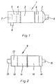
- Figure 1 shows a filter unit 1 with a filter housing 2, in which a particle filter 3 with a downstream or upstream resistance body 4 are arranged.
- a particle filter 3 with a downstream or upstream resistance body 4 In the anteroom 5 with an exhaust gas inlet 6 for the exhaust gas of the diesel engine is a burner 7 for heating provided the same. The cleaned exhaust gas leaves the filter housing 2 through an exhaust outlet 8.
- the particle filter 3 is a wound filter with filter cartridges or - preferably - designed as a honeycomb filter.
- the particle filter has a load-independent flow resistance from 5% to 10% of the flow resistance at the regeneration threshold on, creating a gas pressure required for regeneration is ensured during the entire regeneration.
- the resistance bodies 4 are arranged immediately after or in front of the particle filter 3. This ensures an even flow distribution across the cross-section of the particle filter 3 ensured.
- the flow resistance of the Resistor body 4 can correspond to the respective installation conditions to get voted.
- FIG. 2 shows a stationary regeneration device 9.
- a stationary resistance body 11 and a prechamber 12 are arranged, into which a regeneration gas generator 13 opens. This essentially exists from an air blower and an electric heater.
- a replaceable filter housing 14 is located on the stationary regeneration device 9 attachable with an outlet 15.
- the easy-change filter housing 14 is a Easy-change filter 16 arranged.
- the flow resistance of the stationary Resistor body 11 is in the range of the flow resistance of the loaded spin-on filter 16. This results in a very even loading of the easy-change filter 16 with regeneration gas and thus a quick one and enables thorough regeneration.
- the particle filter 3 or the resistance body 4, 11 becomes one complete regeneration and thus the original loading time reached, because the pressure of the regeneration gas due to the increased load independent Flow resistance until complete regeneration of the particle filter has the required height. To this Way is an increase in the life of the particle filter without noticeable Increased fuel consumption of the diesel engine realized.
Landscapes
- Engineering & Computer Science (AREA)
- Chemical & Material Sciences (AREA)
- Combustion & Propulsion (AREA)
- Mechanical Engineering (AREA)
- General Engineering & Computer Science (AREA)
- Filtering Of Dispersed Particles In Gases (AREA)
- Processes For Solid Components From Exhaust (AREA)
- Lubrication Details And Ventilation Of Internal Combustion Engines (AREA)
- Piezo-Electric Or Mechanical Vibrators, Or Delay Or Filter Circuits (AREA)
- Filtering Materials (AREA)
Applications Claiming Priority (2)
| Application Number | Priority Date | Filing Date | Title |
|---|---|---|---|
| DE19701684 | 1997-01-20 | ||
| DE19701684A DE19701684A1 (de) | 1997-01-20 | 1997-01-20 | Partikelfilter |
Publications (2)
| Publication Number | Publication Date |
|---|---|
| EP0854274A1 true EP0854274A1 (fr) | 1998-07-22 |
| EP0854274B1 EP0854274B1 (fr) | 2002-04-03 |
Family
ID=7817750
Family Applications (1)
| Application Number | Title | Priority Date | Filing Date |
|---|---|---|---|
| EP97121164A Expired - Lifetime EP0854274B1 (fr) | 1997-01-20 | 1997-12-03 | Filtre à particules |
Country Status (3)
| Country | Link |
|---|---|
| EP (1) | EP0854274B1 (fr) |
| AT (1) | ATE215667T1 (fr) |
| DE (2) | DE19701684A1 (fr) |
Families Citing this family (1)
| Publication number | Priority date | Publication date | Assignee | Title |
|---|---|---|---|---|
| DE102017218862A1 (de) | 2017-10-23 | 2018-09-13 | Audi Ag | Verfahren und Vorrichtung zur Bauteilerkennung |
Citations (5)
| Publication number | Priority date | Publication date | Assignee | Title |
|---|---|---|---|---|
| US4492079A (en) * | 1981-03-30 | 1985-01-08 | Nippon Soken, Inc. | Method and apparatus for detecting degree of clogging in particle trapping member of internal combustion engine |
| EP0472008A2 (fr) * | 1990-08-21 | 1992-02-26 | Firma J. Eberspächer | Filtre à particules régénérable par combustion pour les gaz d'échappement de moteurs à combustion interne |
| EP0549851A1 (fr) * | 1992-01-03 | 1993-07-07 | ERNST-APPARATEBAU GmbH & Co. | Filtre à suie pour moteurs diesel |
| EP0507116B1 (fr) * | 1991-04-05 | 1994-12-07 | Firma J. Eberspächer | Filtre à particules régénérable par combustion pour les gaz d'échappement de moteurs à combustion interne |
| US5458664A (en) * | 1992-05-13 | 1995-10-17 | Sumitomo Electric Industries, Ltd. | Particulate trap for purifying diesel engine exhaust |
Family Cites Families (3)
| Publication number | Priority date | Publication date | Assignee | Title |
|---|---|---|---|---|
| DE2930969C2 (de) * | 1979-07-31 | 1987-01-22 | Daimler-Benz Ag, 7000 Stuttgart | Rußfilter im Abströmweg der Abgase einer Brennkraftmaschine |
| DE3602038C1 (de) * | 1986-01-24 | 1987-01-02 | Pattas Konstantin N | Verfahren und Vorrichtung zur Regenerierung eines Dieselrussfilters |
| DE4222162C2 (de) * | 1991-07-06 | 1997-02-20 | Klaus Juergen Nord | Verfahren zum raschen Erzielen der Zündtemperatur der Schadstoffe in den Abgasen einer Brennkraftmaschine und Vorrichtung hierzu |
-
1997
- 1997-01-20 DE DE19701684A patent/DE19701684A1/de not_active Withdrawn
- 1997-12-03 EP EP97121164A patent/EP0854274B1/fr not_active Expired - Lifetime
- 1997-12-03 DE DE59706856T patent/DE59706856D1/de not_active Expired - Lifetime
- 1997-12-03 AT AT97121164T patent/ATE215667T1/de active
Patent Citations (5)
| Publication number | Priority date | Publication date | Assignee | Title |
|---|---|---|---|---|
| US4492079A (en) * | 1981-03-30 | 1985-01-08 | Nippon Soken, Inc. | Method and apparatus for detecting degree of clogging in particle trapping member of internal combustion engine |
| EP0472008A2 (fr) * | 1990-08-21 | 1992-02-26 | Firma J. Eberspächer | Filtre à particules régénérable par combustion pour les gaz d'échappement de moteurs à combustion interne |
| EP0507116B1 (fr) * | 1991-04-05 | 1994-12-07 | Firma J. Eberspächer | Filtre à particules régénérable par combustion pour les gaz d'échappement de moteurs à combustion interne |
| EP0549851A1 (fr) * | 1992-01-03 | 1993-07-07 | ERNST-APPARATEBAU GmbH & Co. | Filtre à suie pour moteurs diesel |
| US5458664A (en) * | 1992-05-13 | 1995-10-17 | Sumitomo Electric Industries, Ltd. | Particulate trap for purifying diesel engine exhaust |
Also Published As
| Publication number | Publication date |
|---|---|
| ATE215667T1 (de) | 2002-04-15 |
| DE59706856D1 (de) | 2002-05-08 |
| EP0854274B1 (fr) | 2002-04-03 |
| DE19701684A1 (de) | 1998-07-23 |
Similar Documents
| Publication | Publication Date | Title |
|---|---|---|
| DE602004011176T2 (de) | Vorrichtung zum Filtern und Brennen von Teilchenmaterial | |
| DE4111029C2 (de) | Durch Freibrennen regenerierbarer Partikelfilter für die Abgase von Brennkraftmaschinen | |
| AT396966B (de) | Abgasfilter für dieselmotoren | |
| DE2953010C2 (fr) | ||
| DE4290489C2 (de) | Abgasreinigungssystem für einen Dieselmotor und Verfahren zum Regenerieren von Keramikfiltern | |
| DE69402437T2 (de) | Partikelabscheider | |
| DE2519609A1 (de) | Vorrichtung zum entfernen des russes aus abgasen von brennkraftmaschinen, insbesondere dieselbrennkraftmaschinen | |
| DE3538155A1 (de) | Verfahren zur oxidation von in russfiltersystemen abgelagerten partikeln | |
| EP0472008B1 (fr) | Filtre à particules régénérable par combustion pour les gaz d'échappement de moteurs à combustion interne | |
| DE4005189A1 (de) | Abgasreinigungsvorrichtung fuer einen dieselmotor | |
| DE3526135A1 (de) | Katalytischer konverter fuer einen dieselmotor und konverterregenerierverfahren | |
| DE3686278T2 (de) | Verfahren und vorrichtung zum filtern von festen teilchen aus einem dieselmotorauspuff. | |
| DE102005023518B4 (de) | Verstopfungsfreies Filteraggregat mit hohem Wirkungsgrad | |
| DE102014100766B4 (de) | Verfahren und Vorrichtung zum Prüfen von Diesel-Partikelfiltern (DPF) | |
| DE60212245T3 (de) | Verfahren und Vorrichtung zur Entfernung von Russpartikeln aus dem Abgas eines Dieselmotors | |
| DE3545437C2 (fr) | ||
| DE4207005C2 (de) | Abgasreiniger | |
| EP0854274B1 (fr) | Filtre à particules | |
| EP0442318B1 (fr) | Filtre à particules régénérable par combustion pour les gaz d'échappement de moteurs à combustion interne | |
| DE102007063100A1 (de) | Abgasnachbehandlungseinrichtung mit mindestens zwei Partikelfiltern | |
| DE102006041284B4 (de) | Verfahren und Vorrichtung zum thermischen Regenerieren von durchströmten Parikelfiltern | |
| DE3723478A1 (de) | Vorrichtung fuer die abscheidung von russ aus dem abgas eines verbrennungsmotors | |
| DE202005011603U1 (de) | Dieselrußpartikelfilter | |
| DE10226108A1 (de) | Abgasanlage mit Partikelfilter für Dieselmotoren | |
| DE4025933C2 (fr) |
Legal Events
| Date | Code | Title | Description |
|---|---|---|---|
| PUAI | Public reference made under article 153(3) epc to a published international application that has entered the european phase |
Free format text: ORIGINAL CODE: 0009012 |
|
| AK | Designated contracting states |
Kind code of ref document: A1 Designated state(s): AT CH DE FR GB IT LI SE |
|
| AX | Request for extension of the european patent |
Free format text: AL;LT;LV;MK;RO;SI |
|
| 17P | Request for examination filed |
Effective date: 19990112 |
|
| AKX | Designation fees paid |
Free format text: AT CH DE FR GB IT LI SE |
|
| RBV | Designated contracting states (corrected) |
Designated state(s): AT CH DE FR GB IT LI SE |
|
| 17Q | First examination report despatched |
Effective date: 20010509 |
|
| GRAG | Despatch of communication of intention to grant |
Free format text: ORIGINAL CODE: EPIDOS AGRA |
|
| GRAG | Despatch of communication of intention to grant |
Free format text: ORIGINAL CODE: EPIDOS AGRA |
|
| GRAH | Despatch of communication of intention to grant a patent |
Free format text: ORIGINAL CODE: EPIDOS IGRA |
|
| GRAH | Despatch of communication of intention to grant a patent |
Free format text: ORIGINAL CODE: EPIDOS IGRA |
|
| REG | Reference to a national code |
Ref country code: GB Ref legal event code: IF02 |
|
| GRAA | (expected) grant |
Free format text: ORIGINAL CODE: 0009210 |
|
| AK | Designated contracting states |
Kind code of ref document: B1 Designated state(s): AT CH DE FR GB IT LI SE |
|
| REF | Corresponds to: |
Ref document number: 215667 Country of ref document: AT Date of ref document: 20020415 Kind code of ref document: T |
|
| REG | Reference to a national code |
Ref country code: CH Ref legal event code: EP |
|
| GBT | Gb: translation of ep patent filed (gb section 77(6)(a)/1977) |
Effective date: 20020404 |
|
| REF | Corresponds to: |
Ref document number: 59706856 Country of ref document: DE Date of ref document: 20020508 |
|
| REG | Reference to a national code |
Ref country code: CH Ref legal event code: NV Representative=s name: R. A. EGLI & CO. PATENTANWAELTE |
|
| ET | Fr: translation filed | ||
| PLBE | No opposition filed within time limit |
Free format text: ORIGINAL CODE: 0009261 |
|
| STAA | Information on the status of an ep patent application or granted ep patent |
Free format text: STATUS: NO OPPOSITION FILED WITHIN TIME LIMIT |
|
| 26N | No opposition filed |
Effective date: 20030106 |
|
| PGFP | Annual fee paid to national office [announced via postgrant information from national office to epo] |
Ref country code: IT Payment date: 20061231 Year of fee payment: 10 |
|
| PGFP | Annual fee paid to national office [announced via postgrant information from national office to epo] |
Ref country code: SE Payment date: 20081117 Year of fee payment: 12 |
|
| PGFP | Annual fee paid to national office [announced via postgrant information from national office to epo] |
Ref country code: GB Payment date: 20081120 Year of fee payment: 12 |
|
| PG25 | Lapsed in a contracting state [announced via postgrant information from national office to epo] |
Ref country code: IT Free format text: LAPSE BECAUSE OF NON-PAYMENT OF DUE FEES Effective date: 20071203 |
|
| EUG | Se: european patent has lapsed | ||
| GBPC | Gb: european patent ceased through non-payment of renewal fee |
Effective date: 20091203 |
|
| PG25 | Lapsed in a contracting state [announced via postgrant information from national office to epo] |
Ref country code: GB Free format text: LAPSE BECAUSE OF NON-PAYMENT OF DUE FEES Effective date: 20091203 |
|
| PGFP | Annual fee paid to national office [announced via postgrant information from national office to epo] |
Ref country code: AT Payment date: 20101214 Year of fee payment: 14 |
|
| PG25 | Lapsed in a contracting state [announced via postgrant information from national office to epo] |
Ref country code: SE Free format text: LAPSE BECAUSE OF NON-PAYMENT OF DUE FEES Effective date: 20091204 |
|
| PGFP | Annual fee paid to national office [announced via postgrant information from national office to epo] |
Ref country code: CH Payment date: 20111227 Year of fee payment: 15 Ref country code: FR Payment date: 20120105 Year of fee payment: 15 |
|
| PGFP | Annual fee paid to national office [announced via postgrant information from national office to epo] |
Ref country code: DE Payment date: 20121029 Year of fee payment: 16 |
|
| REG | Reference to a national code |
Ref country code: CH Ref legal event code: PL |
|
| REG | Reference to a national code |
Ref country code: AT Ref legal event code: MM01 Ref document number: 215667 Country of ref document: AT Kind code of ref document: T Effective date: 20121203 |
|
| REG | Reference to a national code |
Ref country code: FR Ref legal event code: ST Effective date: 20130830 |
|
| PG25 | Lapsed in a contracting state [announced via postgrant information from national office to epo] |
Ref country code: AT Free format text: LAPSE BECAUSE OF NON-PAYMENT OF DUE FEES Effective date: 20121203 Ref country code: LI Free format text: LAPSE BECAUSE OF NON-PAYMENT OF DUE FEES Effective date: 20121231 Ref country code: CH Free format text: LAPSE BECAUSE OF NON-PAYMENT OF DUE FEES Effective date: 20121231 |
|
| PG25 | Lapsed in a contracting state [announced via postgrant information from national office to epo] |
Ref country code: FR Free format text: LAPSE BECAUSE OF NON-PAYMENT OF DUE FEES Effective date: 20130102 |
|
| REG | Reference to a national code |
Ref country code: DE Ref legal event code: R119 Ref document number: 59706856 Country of ref document: DE |
|
| REG | Reference to a national code |
Ref country code: DE Ref legal event code: R119 Ref document number: 59706856 Country of ref document: DE Effective date: 20140701 |
|
| PG25 | Lapsed in a contracting state [announced via postgrant information from national office to epo] |
Ref country code: DE Free format text: LAPSE BECAUSE OF NON-PAYMENT OF DUE FEES Effective date: 20140701 |