EP0854295A1 - Dispositif pour la stérilisation des zones d'élévage aquatiques à l'aide d'ozone - Google Patents
Dispositif pour la stérilisation des zones d'élévage aquatiques à l'aide d'ozone Download PDFInfo
- Publication number
- EP0854295A1 EP0854295A1 EP97115632A EP97115632A EP0854295A1 EP 0854295 A1 EP0854295 A1 EP 0854295A1 EP 97115632 A EP97115632 A EP 97115632A EP 97115632 A EP97115632 A EP 97115632A EP 0854295 A1 EP0854295 A1 EP 0854295A1
- Authority
- EP
- European Patent Office
- Prior art keywords
- water
- ozone
- jet
- jetted
- zone
- Prior art date
- Legal status (The legal status is an assumption and is not a legal conclusion. Google has not performed a legal analysis and makes no representation as to the accuracy of the status listed.)
- Granted
Links
- CBENFWSGALASAD-UHFFFAOYSA-N Ozone Chemical compound [O-][O+]=O CBENFWSGALASAD-UHFFFAOYSA-N 0.000 title claims abstract description 179
- 238000004659 sterilization and disinfection Methods 0.000 title claims abstract description 28
- XLYOFNOQVPJJNP-UHFFFAOYSA-N water Substances O XLYOFNOQVPJJNP-UHFFFAOYSA-N 0.000 claims abstract description 341
- 230000001954 sterilising effect Effects 0.000 claims abstract description 28
- 230000000694 effects Effects 0.000 claims abstract description 24
- 238000004321 preservation Methods 0.000 claims description 22
- 238000011144 upstream manufacturing Methods 0.000 claims description 13
- 241000700605 Viruses Species 0.000 abstract description 7
- 241000233866 Fungi Species 0.000 abstract description 6
- 239000003653 coastal water Substances 0.000 abstract description 6
- 239000002352 surface water Substances 0.000 abstract description 6
- 238000010276 construction Methods 0.000 description 7
- 230000002265 prevention Effects 0.000 description 6
- 238000010521 absorption reaction Methods 0.000 description 4
- 238000011109 contamination Methods 0.000 description 3
- 230000008021 deposition Effects 0.000 description 3
- 241000238565 lobster Species 0.000 description 3
- 239000001301 oxygen Substances 0.000 description 3
- 229910052760 oxygen Inorganic materials 0.000 description 3
- QVGXLLKOCUKJST-UHFFFAOYSA-N atomic oxygen Chemical compound [O] QVGXLLKOCUKJST-UHFFFAOYSA-N 0.000 description 2
- 208000010824 fish disease Diseases 0.000 description 2
- 239000013505 freshwater Substances 0.000 description 2
- 230000002688 persistence Effects 0.000 description 2
- 239000013535 sea water Substances 0.000 description 2
- 241000894006 Bacteria Species 0.000 description 1
- 241000238557 Decapoda Species 0.000 description 1
- FAPWRFPIFSIZLT-UHFFFAOYSA-M Sodium chloride Chemical compound [Na+].[Cl-] FAPWRFPIFSIZLT-UHFFFAOYSA-M 0.000 description 1
- 238000005202 decontamination Methods 0.000 description 1
- 230000003588 decontaminative effect Effects 0.000 description 1
- 230000003247 decreasing effect Effects 0.000 description 1
- 239000007789 gas Substances 0.000 description 1
- 208000015181 infectious disease Diseases 0.000 description 1
- 238000000034 method Methods 0.000 description 1
- 238000012986 modification Methods 0.000 description 1
- 230000004048 modification Effects 0.000 description 1
- 150000002926 oxygen Chemical class 0.000 description 1
- 230000005855 radiation Effects 0.000 description 1
- 238000003756 stirring Methods 0.000 description 1
- 238000005728 strengthening Methods 0.000 description 1
Images


Classifications
-
- F—MECHANICAL ENGINEERING; LIGHTING; HEATING; WEAPONS; BLASTING
- F04—POSITIVE - DISPLACEMENT MACHINES FOR LIQUIDS; PUMPS FOR LIQUIDS OR ELASTIC FLUIDS
- F04F—PUMPING OF FLUID BY DIRECT CONTACT OF ANOTHER FLUID OR BY USING INERTIA OF FLUID TO BE PUMPED; SIPHONS
- F04F5/00—Jet pumps, i.e. devices in which flow is induced by pressure drop caused by velocity of another fluid flow
- F04F5/02—Jet pumps, i.e. devices in which flow is induced by pressure drop caused by velocity of another fluid flow the inducing fluid being liquid
- F04F5/04—Jet pumps, i.e. devices in which flow is induced by pressure drop caused by velocity of another fluid flow the inducing fluid being liquid displacing elastic fluids
-
- A—HUMAN NECESSITIES
- A01—AGRICULTURE; FORESTRY; ANIMAL HUSBANDRY; HUNTING; TRAPPING; FISHING
- A01K—ANIMAL HUSBANDRY; AVICULTURE; APICULTURE; PISCICULTURE; FISHING; REARING OR BREEDING ANIMALS, NOT OTHERWISE PROVIDED FOR; NEW BREEDS OF ANIMALS
- A01K63/00—Receptacles for live fish, e.g. aquaria; Terraria
- A01K63/04—Arrangements for treating water specially adapted to receptacles for live fish
- A01K63/042—Introducing gases into the water, e.g. aerators, air pumps
-
- B—PERFORMING OPERATIONS; TRANSPORTING
- B01—PHYSICAL OR CHEMICAL PROCESSES OR APPARATUS IN GENERAL
- B01F—MIXING, e.g. DISSOLVING, EMULSIFYING OR DISPERSING
- B01F23/00—Mixing according to the phases to be mixed, e.g. dispersing or emulsifying
- B01F23/20—Mixing gases with liquids
- B01F23/23—Mixing gases with liquids by introducing gases into liquid media, e.g. for producing aerated liquids
- B01F23/237—Mixing gases with liquids by introducing gases into liquid media, e.g. for producing aerated liquids characterised by the physical or chemical properties of gases or vapours introduced in the liquid media
- B01F23/2376—Mixing gases with liquids by introducing gases into liquid media, e.g. for producing aerated liquids characterised by the physical or chemical properties of gases or vapours introduced in the liquid media characterised by the gas being introduced
- B01F23/23761—Aerating, i.e. introducing oxygen containing gas in liquids
- B01F23/237613—Ozone
-
- B—PERFORMING OPERATIONS; TRANSPORTING
- B01—PHYSICAL OR CHEMICAL PROCESSES OR APPARATUS IN GENERAL
- B01F—MIXING, e.g. DISSOLVING, EMULSIFYING OR DISPERSING
- B01F23/00—Mixing according to the phases to be mixed, e.g. dispersing or emulsifying
- B01F23/40—Mixing liquids with liquids; Emulsifying
- B01F23/45—Mixing liquids with liquids; Emulsifying using flow mixing
- B01F23/454—Mixing liquids with liquids; Emulsifying using flow mixing by injecting a mixture of liquid and gas
-
- B—PERFORMING OPERATIONS; TRANSPORTING
- B01—PHYSICAL OR CHEMICAL PROCESSES OR APPARATUS IN GENERAL
- B01F—MIXING, e.g. DISSOLVING, EMULSIFYING OR DISPERSING
- B01F25/00—Flow mixers; Mixers for falling materials, e.g. solid particles
- B01F25/20—Jet mixers, i.e. mixers using high-speed fluid streams
- B01F25/21—Jet mixers, i.e. mixers using high-speed fluid streams with submerged injectors, e.g. nozzles, for injecting high-pressure jets into a large volume or into mixing chambers
- B01F25/211—Jet mixers, i.e. mixers using high-speed fluid streams with submerged injectors, e.g. nozzles, for injecting high-pressure jets into a large volume or into mixing chambers the injectors being surrounded by guiding tubes
-
- B—PERFORMING OPERATIONS; TRANSPORTING
- B01—PHYSICAL OR CHEMICAL PROCESSES OR APPARATUS IN GENERAL
- B01F—MIXING, e.g. DISSOLVING, EMULSIFYING OR DISPERSING
- B01F25/00—Flow mixers; Mixers for falling materials, e.g. solid particles
- B01F25/30—Injector mixers
- B01F25/31—Injector mixers in conduits or tubes through which the main component flows
- B01F25/314—Injector mixers in conduits or tubes through which the main component flows wherein additional components are introduced at the circumference of the conduit
-
- B—PERFORMING OPERATIONS; TRANSPORTING
- B01—PHYSICAL OR CHEMICAL PROCESSES OR APPARATUS IN GENERAL
- B01F—MIXING, e.g. DISSOLVING, EMULSIFYING OR DISPERSING
- B01F25/00—Flow mixers; Mixers for falling materials, e.g. solid particles
- B01F25/30—Injector mixers
- B01F25/31—Injector mixers in conduits or tubes through which the main component flows
- B01F25/314—Injector mixers in conduits or tubes through which the main component flows wherein additional components are introduced at the circumference of the conduit
- B01F25/3142—Injector mixers in conduits or tubes through which the main component flows wherein additional components are introduced at the circumference of the conduit the conduit having a plurality of openings in the axial direction or in the circumferential direction
-
- B—PERFORMING OPERATIONS; TRANSPORTING
- B01—PHYSICAL OR CHEMICAL PROCESSES OR APPARATUS IN GENERAL
- B01F—MIXING, e.g. DISSOLVING, EMULSIFYING OR DISPERSING
- B01F25/00—Flow mixers; Mixers for falling materials, e.g. solid particles
- B01F25/30—Injector mixers
- B01F25/31—Injector mixers in conduits or tubes through which the main component flows
- B01F25/314—Injector mixers in conduits or tubes through which the main component flows wherein additional components are introduced at the circumference of the conduit
- B01F25/3142—Injector mixers in conduits or tubes through which the main component flows wherein additional components are introduced at the circumference of the conduit the conduit having a plurality of openings in the axial direction or in the circumferential direction
- B01F25/31423—Injector mixers in conduits or tubes through which the main component flows wherein additional components are introduced at the circumference of the conduit the conduit having a plurality of openings in the axial direction or in the circumferential direction with a plurality of perforations in the circumferential direction only and covering the whole circumference
-
- B—PERFORMING OPERATIONS; TRANSPORTING
- B01—PHYSICAL OR CHEMICAL PROCESSES OR APPARATUS IN GENERAL
- B01F—MIXING, e.g. DISSOLVING, EMULSIFYING OR DISPERSING
- B01F25/00—Flow mixers; Mixers for falling materials, e.g. solid particles
- B01F25/30—Injector mixers
- B01F25/31—Injector mixers in conduits or tubes through which the main component flows
- B01F25/314—Injector mixers in conduits or tubes through which the main component flows wherein additional components are introduced at the circumference of the conduit
- B01F25/3143—Injector mixers in conduits or tubes through which the main component flows wherein additional components are introduced at the circumference of the conduit characterised by the specific design of the injector
- B01F25/31432—Injector mixers in conduits or tubes through which the main component flows wherein additional components are introduced at the circumference of the conduit characterised by the specific design of the injector being a slit extending in the circumferential direction only
-
- C—CHEMISTRY; METALLURGY
- C02—TREATMENT OF WATER, WASTE WATER, SEWAGE, OR SLUDGE
- C02F—TREATMENT OF WATER, WASTE WATER, SEWAGE, OR SLUDGE
- C02F1/00—Treatment of water, waste water, or sewage
- C02F1/72—Treatment of water, waste water, or sewage by oxidation
- C02F1/78—Treatment of water, waste water, or sewage by oxidation with ozone
-
- C—CHEMISTRY; METALLURGY
- C02—TREATMENT OF WATER, WASTE WATER, SEWAGE, OR SLUDGE
- C02F—TREATMENT OF WATER, WASTE WATER, SEWAGE, OR SLUDGE
- C02F7/00—Aeration of stretches of water
-
- F—MECHANICAL ENGINEERING; LIGHTING; HEATING; WEAPONS; BLASTING
- F04—POSITIVE - DISPLACEMENT MACHINES FOR LIQUIDS; PUMPS FOR LIQUIDS OR ELASTIC FLUIDS
- F04F—PUMPING OF FLUID BY DIRECT CONTACT OF ANOTHER FLUID OR BY USING INERTIA OF FLUID TO BE PUMPED; SIPHONS
- F04F5/00—Jet pumps, i.e. devices in which flow is induced by pressure drop caused by velocity of another fluid flow
- F04F5/14—Jet pumps, i.e. devices in which flow is induced by pressure drop caused by velocity of another fluid flow the inducing fluid being elastic fluid
- F04F5/24—Jet pumps, i.e. devices in which flow is induced by pressure drop caused by velocity of another fluid flow the inducing fluid being elastic fluid displacing liquids, e.g. containing solids, or liquids and elastic fluids
-
- B—PERFORMING OPERATIONS; TRANSPORTING
- B01—PHYSICAL OR CHEMICAL PROCESSES OR APPARATUS IN GENERAL
- B01F—MIXING, e.g. DISSOLVING, EMULSIFYING OR DISPERSING
- B01F23/00—Mixing according to the phases to be mixed, e.g. dispersing or emulsifying
- B01F23/20—Mixing gases with liquids
- B01F23/23—Mixing gases with liquids by introducing gases into liquid media, e.g. for producing aerated liquids
-
- Y—GENERAL TAGGING OF NEW TECHNOLOGICAL DEVELOPMENTS; GENERAL TAGGING OF CROSS-SECTIONAL TECHNOLOGIES SPANNING OVER SEVERAL SECTIONS OF THE IPC; TECHNICAL SUBJECTS COVERED BY FORMER USPC CROSS-REFERENCE ART COLLECTIONS [XRACs] AND DIGESTS
- Y02—TECHNOLOGIES OR APPLICATIONS FOR MITIGATION OR ADAPTATION AGAINST CLIMATE CHANGE
- Y02W—CLIMATE CHANGE MITIGATION TECHNOLOGIES RELATED TO WASTEWATER TREATMENT OR WASTE MANAGEMENT
- Y02W10/00—Technologies for wastewater treatment
- Y02W10/10—Biological treatment of water, waste water, or sewage
Definitions
- the present invention relates to an environment preservation measures technique for contamination resulting from the nourishment of an artificially closed water zone such as a bay inside, river mouth zone, lake/marsh, dam, reservoir, water-stored pond, or marine/inland raising bed. More particularly, the invention concerns a raising water-zone environment preservation apparatus which is directed to strengthening an epidemic prevention structure based on the sterilization of an entire closed water zone used as a raising bed by diffusing ozone over a wide range thereof in a short period of time and, before the sterilization effect vanishes, circulating ozone over a wide bottom layer of the water zone to thereby cause the effective spreading of the sterilization effect of the epidemic-causing fungi, virus or the like likely to stay in a part of the water zone interior, water bottom slush surface or coastal water zone.
- gas is only diffused very locally by using mainly a jet flow of air having a locally high strength or by using a flow having a relatively aged energy such as that of an air diffuser.
- Ozone in the conventional environment preservation countermeasures using an ozone apparatus, ozone can be made to come into an in-water dissolved state but its in-water persistence time period is short. Ozone has a strong sterilization effect and therefore is effective for the decontamination and sterilization within the water zone. However, the state of O 3 is not stable and it is said that this O 3 can persist in water only for a time period of 20 to 30 minutes. Therefore, the effect thereof vanishes before the O 3 is sufficiently circulated through the water zone.
- the present invention has been made in view of the above-described problems so as to solve these problems and an object of the present invention is to provide a raising water-zone environment preservation apparatus which can strengthen an epidemic prevention structure based on the sterilization of an entire closed water zone used as a raising bed by diffusing ozone over a wide range thereof in a short period of time and, before the sterilization effect vanishes, circulating ozone over a wide bottom layer of the water zone to thereby cause the effective spreading of the sterilization effect of the epidemic-causing fungi, virus or the like likely to stay in a part of the water zone interior, water bottom slush surface or coastal water zone.
- the present invention is constituted by means (1) wherein a rectifying cylinder interiorly provided with a water jet pump and consisting of a cylindrical body whose both ends are made open so as to improve the water jetting capability of the water jet pump is installed in the water of a closed water zone used as a raising bed, ozone is injected into and mixed with the water jetted from the water jet pump and the resulting water is jetted, and the ozone is thereby diffused into the closed water zone over a wide range in a short period of time to thereby cause the ozone to be circulated over a wide bottom layer of the water zone before the sterilization effect vanishes.
- the present invention is constituted by means (2) wherein a rectifying cylinder interiorly provided with a water jet pump and consisting of a cylindrical body whose both ends are made open so as to improve the water jetting capability of the water jet pump is installed in the water of a closed water zone used as a raising bed, a within-vagina portion opened at its both ends and provided with a water jet pump inflow port and a water jet pump discharge port is formed in such a way as to pass through the interior of the water jet pump, a jet opening for jetting water toward the downstream side is formed in an inner wall surface of a flow passage of the within-vagina portion, a driving water pump for supplying water which is to be jetted from the jet opening is provided, the driving water pump and the jet opening being connected to each other by a driving water supply pipe, ozone jet openings for jetting ozone which is absorbed by the water jetted from the jet opening and injected into and mixed with the water in the flow passage are formed in the inner wall surface of the flow passage of the within-vagina
- a floating body may be caused to float on a water surface of the closed water zone used as a raising bed, whereby the driving water pump and the ozone producer may be installed on the floating body.
- the present invention is constituted by means (3) wherein a rectifying cylinder interiorly provided with a water jet pump and consisting of a cylindrical body whose both ends are made open so as to improve the water jetting capability of the water jet pump is installed in the water of a closed water zone used as a raising bed, a within-vagina portion opened at its both ends and provided with a water jet pump inflow port and a water jet pump discharge port is formed in such a way as to pass through the interior of the water jet pump, a jet opening for jetting water toward the downstream side is formed in an inner wall surface of a flow passage of the within-vagina portion, a driving water pump for supplying water which is to be jetted from the jet opening is provided, the driving water pump and the jet opening being connected to each other by a driving water supply pipe, an ozone jet helicoid groove for jetting ozone which is absorbed by the water jetted from the jet opening and injected into and mixed with the water in the flow passage is formed in the inner wall surface of the flow passage of
- a floating body may be caused to float on a water surface of the closed water zone used as a raising bed, whereby the driving water pump and the ozone producer may be installed on the floating body.
- the present invention is constituted by means (4) wherein a rectifying cylinder interiorly provided with a water jet pump and consisting of a cylindrical body whose both ends are made open so as to improve the water jetting capability of the water jet pump is installed in the water of a closed water zone used as a raising bed, a within-vagina portion opened at its both ends and provided with a water jet pump inflow port and a water jet pump discharge port is formed in such a way as to pass through the interior of the water jet pump, a jet opening for jetting water toward the downstream side is formed in an inner wall surface of a flow passage of the within-vagina portion, a driving water pump for supplying water which is to be jetted from the jet opening is provided, the driving water pump and the jet opening being connected to each other by a driving water supply pipe, a jetted ozone stagnation groove for jetting ozone which is absorbed by the water jetted from the jet opening and injected into and mixed with the water in the flow passage is formed in the inner wall surface of the flow passage of
- a floating body may be caused to float on a water surface of the closed water zone used as a raising bed, whereby the driving water pump and the ozone producer may be installed on the floating body.
- the raising water zone environment preservation apparatus of the inventions (1) to (4) there is brought about a very novel advantageous effect of making it possible to strengthen an epidemic prevention structure based on the sterilization of an entire closed water zone used as a raising bed by diffusing ozone over a wide range thereof in a short period of time and, before the sterilization effect vanishes, circulating ozone over a wide bottom layer of the water zone to thereby cause the effective wider spreading of the sterilization effect of the epidemic-causing fungi, virus or the like likely to stay in a part of the water zone interior, water bottom slush surface or coastal water zone.
- ozone supplied by way of the ozone supply pipe can be injected into and mixed with the water flowing through the interior of the within-vagina portion of the water jet pump with a high speed while ozone is being absorbed and jetted from the ozone jet openings by a high-speed flow of the water in the within-vagina portion of the water jet pump.
- ozone supplied by way of the ozone supply pipe can be injected into and mixed with the water flowing through the interior of the within-vagina portion of the water jet pump with a high speed while ozone is being helically rotated along the helicoid groove of the ozone jet helicoid groove and while ozone is being absorbed by a high-speed flow of the water in the within-vagina portion of the water jet pump.
- ozone supplied by way of the ozone supply pipe can be caused to flow along the stagnation groove of the jetted ozone stagnation groove and temporarily caused to stay therein, whereby ozone having been temporarily stagnated in the jetted ozone stagnation groove can be injected into and mixed with the water flowing through the interior of the within-vagina portion with a high speed while ozone is being absorbed by the high-speed flow of the water in the within-vagina portion of the water jet pump and is being taken away from the jetted ozone stagnation groove.
- the raising water zone environment preservation apparatus can be freely installed in a given closed water zone which is distant from a land.
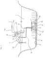
- Fig. 1 is a schematic side sectional view illustrating a first embodiment as a whole of the present invention
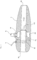
- Fig. 2 is a sectional view illustrating a water jet pump thereof.
- the rectifying cylinder 5 interiorly provided with the water jet pump 4 serves to strengthen an epidemic prevention structure based on the sterilization of the entire closed water zone 1 used as a raising bed by diffusing ozone over a wide range thereof in a short period of time and, before the sterilization effect vanishes, circulating ozone over a wide bottom layer of the closed water zone to thereby cause the effective spreading of the sterilization effect of the epidemic-causing fungi, virus or the like likely to stay in a part of the water zone interior, water bottom slush surface or coastal water zone.
- the rectifying cylinder 5 functions to further improve the function of the water jet pump 4 interiorly provided therein.
- the rectifying cylinder 5 functions to stir the closed water zone 1 in a short period of time by preventing the water jetted from the water jet pump 4 from being dispersed immediately after this water is jetted and thereby causing it to be jetted straightforward to a further distant place and thereafter diffused in this distant place. While the rectifying cylinder 5 is installed on the water bottom 2 of the closed water zone 1 so that its open both ends may become substantially horizontally arranged, there may be also a case where the rectifying cylinder 5 is installed at a given angle of inclination if necessary.
- the rectifying cylinder 5 consists of a circular cylindrical body and the both ends thereof are made open. One open end thereof is a water inlet 5a and the other open end thereof is a water outlet 5b. Under the rectifying cylinder 5, there are mounted support portions 5c for supporting the rectifying cylinder 5 by installing this rectifying cylinder 5 horizontally on the water bottom 2 side, respectively, at front and rear sides as viewed in the cylinder-axial direction.
- the water jet pump 4 which will be later described.
- the water jet pump 4 is mounted such that the axial direction thereof is in coincidence with the cylinder-axial direction of the rectifying cylinder 5. It is arranged that the jetting direction of the water jetted from the water jet pump 4 is the same as the cylinder-axial direction of the rectifying cylinder 5 and that the water having flown from one open end of the rectifying cylinder 5 is jetted and discharged from the other end thereof which is located on a side opposite to this one open end.
- within the water jet pump 4 there is formed a within-vagina portion 4a serving as a flow passage and opened at its both ends.
- the within-vagina portion 4a is formed in the longitudinal direction of the water jet pump 4, i.e., the axial direction thereof.
- the within-vagina portion 4a is shaped like a circular cylinder and a downstream end of the circular-cylindrical within-vagina portion 4a has a water jet pump discharge port 4b.
- An upstream end of the within-vagina portion 4a has a water jet pump inflow port 4c.
- a jet opening 4d for jetting water is formed in the inner-circumferential direction.
- the jet opening 4d is formed over one entire circumference of the inner periphery of the within-vagina portion 4a.
- the jet opening 4d formed over one entire circumference is formed being directed slantwise toward the water jet pump discharge port 4b on the downstream side of the within-vagina portion 4a.
- the water jetted from the jet opening 4d formed being directed slantwise toward the water jet pump discharge port 4b is jetted with a high speed toward the water jet pump discharge port 4b on the downstream end of the within-vagina portion 4a, with the result that a negative zone is developed on the downstream side from the jet opening 4d by this high-speed jet flow of the water.
- this jet flow functions to absorb and discharge ozone as later described.
- an annular driving water chamber 4e communicated with the jet opening 4d.
- the driving water chamber 4e is a supply portion for supplying water which is to be jetted from the jet opening 4d and, on the downstream side therefrom, the jet opening 4d is formed such that this opening is communicated with the driving water chamber 4e.
- the driving water pump 7 is an equipment which supplies water of the closed water zone 1 as a jet water to the water jet pump 4 by way of the driving water supply pump 6 through circulation.
- a plurality of ozone jet openings 8 for jetting ozone are formed in the inner wall surface of the flow passage located on the upstream side of the jet opening 4d of the within-vagina portion 4a circumferentially at equal intervals.
- the ozone jet openings 8 are formed being directed slantwise toward the water jet pump discharge port 4b located at the downstream end of the within-vagina portion 4a.
- the ozone jet openings 8 are so arranged as to absorb and discharge ozone injected by the water jetted from the jet opening 4d of the downstream side.
- an annular ozone supply chamber 8a communicated with the ozone jet openings 8.
- the ozone supply chamber 8a is located on the upstream side of the driving water chamber 4e.
- the ozone supply chamber 8a is a supply portion for supplying ozone injected from the ozone jet openings 8 and, on the downstream side therefrom, the ozone jet openings 8 are formed such that these openings are communicated with the ozone jet chamber 8a.
- the ozone producer 10 is an equipment which supplies ozone produced therein to the water jet pump 4 by way of the ozone supply pump 9.
- the ozone producer 10 consists of an equipment for radiating, for example, ultraviolet rays with respect to oxygen in the air and converting this oxygen to ozone.
- a far ultraviolt ozone ray discharge tube 11 for radiating ultraviolet rays.
- a power source device 11b is provided for supplying power to the far ultraviolet ozone ray discharge tube 11 through a power source line 11a.
- An air compressor 12 for supplying air to the ozone producer 10 is provided outside this ozone producer 10 in a state of being connected thereto.
- the floating body 13 is a structure which floats on the water surface of the closed water zone 1.
- the equipments such as the driving water pump 7 for supplying jet water to the water jet pump 4, ozone producer 10, air compressor 12, etc. so as to enable the water jet pump 4 to be used at a given position of the closed water zone 1.
- the equipments such as the driving water pump 7, ozone producer 10, air compressor 12, etc. may be installed on a land as in the prior art.
- the driving pump 7 and air compressor 12 installed on the floating body 13 are driven.
- the driving water pump 7 When driving the driving water pump 7 installed on the floating body 13, the driving water pump 7 takes in water of the closed water zone 1, forces this water to be carried through the driving water supply pipe 6, and supplies this water to the water jet pump 4 inside the rectifying cylinder 5 installed on the bottom 2 of water.
- the air compressor 12 when driving the air compressor 12 installed on the floating body 13, the air compressor 12 absorbs and compresses air in the atmosphere and sends the resulting air into the ozone producer 10.
- the ozone producer 10 is provided with the far ultraviolet ozone ray discharge tube 11.
- the ozone producer 10 converts a part of oxygen in the air sent therein to ozone by the far ultraviolet ozone ray radiation to thereafter cause this ozone to flow downward through the ozone supply pipe 9 to the water jet pump 4 inside the rectifying cylinder 5 installed on the water bottom 2.
- the water supplied to the water jet pump 4 through the driving water supply pipe 6 enters into the annular driving water chamber 4e formed inside the water jet pump 4. Then, the water is supplied from the driving water chamber 4e to the jet opening 4d located on the outlet side of the driving water chamber 4e. Then, the water is jetted from the jet opening 4d to the within-vagina portion 4a.
- the water having been jetted from the jet opening 4d to the within-vagina 4a is jetted with a high speed toward the water jet pump discharge port 4b side.
- the water jetted with a high speed is extruded from the jet opening 4d of the within-vagina portion 4a toward the water jet pump discharge port 4b with a high speed.
- the water which has flown in is caused to flow, by absorption, up to the position of the within-vagina portion 4a where the jet opening 4d is formed and thereafter is extruded with a high speed toward the water jet pump discharge port 4b side by the water which is jetted from the jet opening 4d toward the downstream side thereof.
- the ozone having been supplied to the water jet pump 4 through the ozone supply pipe 9 enters into the annular ozone supply chamber 8a formed inside the water jet pump 4.
- This ozone is sent from the ozone supply chamber 8a to the ozone jet openings 8 located on the outlet side thereof and then is absorbed and jetted therefrom into the within-vagina portion 4a.
- the area of the within-vagina portion 4a where the ozone jet openings 8 are formed falls within the negative zone due to the action of the water jetted from the jet opening 4d.
- the ozone is absorbed and jetted from the ozone jet openings 8.
- the ozone absorbed and jetted from the ozone jet openings 8 to the within-vagina portion 4a is injected into and mixed with the water flowing through the within-vagina portion 4a toward the water jet pump discharge port 4b side with a high speed.
- the ozone comes into a state of very fine air bubbles and the resulting water becomes an ozone mixed water tending to be less floated.
- This resulting water is jetted from the water jet pump discharge port 4b of the water jet pump 4 with a high speed.
- the ozone mixed water which has been jetted from the water jet pump discharge port 4b with a high speed passes through the cylindrical body of the rectifying cylinder 5 interiorly provided with the water jet pump 4 and is discharged to the external bottom layer side of the closed water zone 1 with a high speed.
- the ozone mixed water which has been jetted from the water jet pump discharge port 4b with a high speed is prevented from being dispersed around the water jet pump 4 immediately after the jetting therefrom.
- the power with which the ozone mixed water is jetted is prevented from being decreased. That is, the ozone mixed water can be jetted up to a distant place with a high straightforwardness. As a result, the ozone mixed water can be sent out to a distant place on the bottom layer side of the closed water zone 1 in a short period of time.
- FIG. 3 is a sectional view illustrating a water jet pump according to a second embodiment of the present invention.
- this second embodiment lies in the construction of the portion formed in the within-vagina portion 4a of the water jet pump 4 and serving to jet ozone. Since the other construction is the same as the construction of the first embodiment, the same components are denoted by like reference symbols and an explanation thereof will be omitted. Also, since the function thereof also is the same as in the case of the first embodiment, an explanation thereof will be omitted.
- ozone jet helicoid groove 18 for jetting ozone.
- a forward end side of the ozone supply pipe 9 is inserted into and connected to the upstream side of the helical ozone jet helicoid groove 18.
- the ozone supplied from the ozone supply pipe 9 is so arranged as to be injected into and mixed with the water flowing through the within-vagina portion 4a with a high speed while being helically rotated along the helicoid groove of the ozone jet helicoid groove 18.
- FIG. 4 is a sectional view illustrating a water jet pump according to a third embodiment of the present invention.
- this third embodiment lies in the construction of the portion formed in the within-vagina portion 4a of the water jet pump 4 and serving to jet ozone. Since the other construction is the same as the construction of the first embodiment, the same components are denoted by like reference symbols and an explanation thereof will be omitted. Also, since the function thereof also is the same as in the case of the first embodiment, an explanation thereof will be omitted.
- a jetted ozone stagnation groove 28 for jetting ozone over one entire circumference thereof.
- the jetted ozone stagnation groove 28 is formed being gently directed toward the water jet pump discharge port 4b so as to make the jet of ozone easy.
- the jetted ozone stagnation groove 28 is recessed as a concavity when viewed toward the water jet pump inflow port 4c side, whereby it is arranged that the water flowing through the within-vagina portion 4a with a high speed is unlikely to enter into the jetted ozone stagnation groove 28.
- a forward end side of the ozone supply pipe 9 is inserted into and connected to the jetted ozone stagnation groove 28.
- the ozone supplied from the ozone supply pipe 9 is so arranged as to be temporarily stagnated by flowing along the stagnation groove of the jetted ozone stagnation groove 28.
- the ozone which has been temporarily stagnated in the jetted ozone stagnation groove 28 is so arranged as to be absorbed by the high-speed flow of the water in the within-vagina portion 4a and taken away from the jetted ozone stagnation groove 28 and thus injected into and mixed with the water flowing through the within-vagina portion 4a with a high speed.
Landscapes
- Chemical & Material Sciences (AREA)
- Chemical Kinetics & Catalysis (AREA)
- Engineering & Computer Science (AREA)
- Life Sciences & Earth Sciences (AREA)
- General Engineering & Computer Science (AREA)
- Fluid Mechanics (AREA)
- Water Supply & Treatment (AREA)
- Organic Chemistry (AREA)
- Hydrology & Water Resources (AREA)
- Environmental & Geological Engineering (AREA)
- Mechanical Engineering (AREA)
- Environmental Sciences (AREA)
- Physics & Mathematics (AREA)
- Animal Husbandry (AREA)
- Biodiversity & Conservation Biology (AREA)
- Marine Sciences & Fisheries (AREA)
- Treatment Of Water By Oxidation Or Reduction (AREA)
- Aeration Devices For Treatment Of Activated Polluted Sludge (AREA)
- Oxygen, Ozone, And Oxides In General (AREA)
- Apparatus For Disinfection Or Sterilisation (AREA)
- Catching Or Destruction (AREA)
Applications Claiming Priority (3)
| Application Number | Priority Date | Filing Date | Title |
|---|---|---|---|
| JP2331197A JP3290085B2 (ja) | 1997-01-21 | 1997-01-21 | 養殖場水域環境保全装置 |
| JP23311/97 | 1997-01-21 | ||
| JP2331197 | 1997-01-21 |
Publications (2)
| Publication Number | Publication Date |
|---|---|
| EP0854295A1 true EP0854295A1 (fr) | 1998-07-22 |
| EP0854295B1 EP0854295B1 (fr) | 2003-05-07 |
Family
ID=12107054
Family Applications (1)
| Application Number | Title | Priority Date | Filing Date |
|---|---|---|---|
| EP97115632A Expired - Lifetime EP0854295B1 (fr) | 1997-01-21 | 1997-09-09 | Dispositif pour la stérilisation des zones d'élévage aquatiques à l'aide d'ozone |
Country Status (6)
| Country | Link |
|---|---|
| EP (1) | EP0854295B1 (fr) |
| JP (1) | JP3290085B2 (fr) |
| ES (1) | ES2197963T3 (fr) |
| ID (1) | ID19655A (fr) |
| IL (1) | IL121767A (fr) |
| TW (1) | TW362950B (fr) |
Cited By (7)
| Publication number | Priority date | Publication date | Assignee | Title |
|---|---|---|---|---|
| WO2000074830A1 (fr) * | 1999-06-03 | 2000-12-14 | Donovan Graham Ellam | Melangeurs entraines par un fluide |
| WO2003061814A1 (fr) * | 2002-01-25 | 2003-07-31 | Seair Inc. | Diffuseur et appareil d'aeration equipe d'un tel diffuseur |
| WO2003086988A1 (fr) * | 2002-04-18 | 2003-10-23 | Hollandsche Beton Groep N.V. | Procede pour traiter des eaux et leurs sediments |
| WO2011101637A1 (fr) * | 2010-02-17 | 2011-08-25 | Pursuit Dynamics Plc | Appareil et procédé pour l'entraînement de fluides |
| WO2016050374A1 (fr) * | 2014-09-29 | 2016-04-07 | Heimgård Bjørn Egil | Système d'aération |
| US9533267B2 (en) | 2012-01-31 | 2017-01-03 | Seair Inc. | Multi-stage aeration apparatus |
| CN109382008A (zh) * | 2017-08-08 | 2019-02-26 | 肇庆市高新区笙辉机械有限公司 | 一种多功能臭氧水机 |
Families Citing this family (6)
| Publication number | Priority date | Publication date | Assignee | Title |
|---|---|---|---|---|
| JP2003053372A (ja) * | 2001-08-22 | 2003-02-25 | Nippon Chutetsukan Kk | 水浄化装置 |
| JP2004290863A (ja) * | 2003-03-27 | 2004-10-21 | Narasaki Seisakusho:Kk | 底水域における水質改善方法及び装置 |
| JP2008173553A (ja) * | 2007-01-17 | 2008-07-31 | Chugoku Electric Power Co Inc:The | 水質改善装置 |
| JP5257819B2 (ja) * | 2011-02-25 | 2013-08-07 | 成和工業株式会社 | マイクロバブル発生器 |
| CN114100481A (zh) * | 2021-12-16 | 2022-03-01 | 东北大学秦皇岛分校 | 一种小型多功能消毒液混合制备装置 |
| KR102810578B1 (ko) * | 2022-12-26 | 2025-05-20 | 한국해양과학기술원 | 수층 교반에 의한 어장환경을 개선하기 위한 이동식 에어버블 장치 |
Citations (7)
| Publication number | Priority date | Publication date | Assignee | Title |
|---|---|---|---|---|
| US4019983A (en) * | 1974-10-10 | 1977-04-26 | Houdaille Industries, Inc. | Disinfection system and method |
| JPH05293479A (ja) * | 1992-04-21 | 1993-11-09 | Hitachi Kiden Kogyo Ltd | 水域の浄化方法 |
| JPH05340400A (ja) * | 1992-06-05 | 1993-12-21 | Mitsubishi Heavy Ind Ltd | 水流発生装置 |
| US5403522A (en) * | 1993-11-12 | 1995-04-04 | Von Berg; Richard | Apparatus and methods for mixing liquids and flowable treating agents |
| US5514267A (en) * | 1992-05-14 | 1996-05-07 | Idec Izumi Corporation | Apparatus for dissolving a gas into and mixing the same with a liquid |
| US5525242A (en) * | 1994-10-19 | 1996-06-11 | Kerecz; Robert C. J. | Apparatus and process for the aeration of water |
| JPH08200300A (ja) * | 1995-01-30 | 1996-08-06 | Mitsubishi Heavy Ind Ltd | 空気混入式水流発生装置 |
-
1997
- 1997-01-21 JP JP2331197A patent/JP3290085B2/ja not_active Expired - Lifetime
- 1997-08-27 TW TW086112332A patent/TW362950B/zh active
- 1997-09-09 ES ES97115632T patent/ES2197963T3/es not_active Expired - Lifetime
- 1997-09-09 EP EP97115632A patent/EP0854295B1/fr not_active Expired - Lifetime
- 1997-09-15 IL IL12176797A patent/IL121767A/xx not_active IP Right Cessation
- 1997-10-03 ID ID973353A patent/ID19655A/id unknown
Patent Citations (7)
| Publication number | Priority date | Publication date | Assignee | Title |
|---|---|---|---|---|
| US4019983A (en) * | 1974-10-10 | 1977-04-26 | Houdaille Industries, Inc. | Disinfection system and method |
| JPH05293479A (ja) * | 1992-04-21 | 1993-11-09 | Hitachi Kiden Kogyo Ltd | 水域の浄化方法 |
| US5514267A (en) * | 1992-05-14 | 1996-05-07 | Idec Izumi Corporation | Apparatus for dissolving a gas into and mixing the same with a liquid |
| JPH05340400A (ja) * | 1992-06-05 | 1993-12-21 | Mitsubishi Heavy Ind Ltd | 水流発生装置 |
| US5403522A (en) * | 1993-11-12 | 1995-04-04 | Von Berg; Richard | Apparatus and methods for mixing liquids and flowable treating agents |
| US5525242A (en) * | 1994-10-19 | 1996-06-11 | Kerecz; Robert C. J. | Apparatus and process for the aeration of water |
| JPH08200300A (ja) * | 1995-01-30 | 1996-08-06 | Mitsubishi Heavy Ind Ltd | 空気混入式水流発生装置 |
Non-Patent Citations (3)
| Title |
|---|
| PATENT ABSTRACTS OF JAPAN vol. 018, no. 093 (C - 1166) 16 February 1994 (1994-02-16) * |
| PATENT ABSTRACTS OF JAPAN vol. 018, no. 183 (M - 1584) 29 March 1994 (1994-03-29) * |
| PATENT ABSTRACTS OF JAPAN vol. 096, no. 012 26 December 1996 (1996-12-26) * |
Cited By (10)
| Publication number | Priority date | Publication date | Assignee | Title |
|---|---|---|---|---|
| WO2000074830A1 (fr) * | 1999-06-03 | 2000-12-14 | Donovan Graham Ellam | Melangeurs entraines par un fluide |
| WO2003061814A1 (fr) * | 2002-01-25 | 2003-07-31 | Seair Inc. | Diffuseur et appareil d'aeration equipe d'un tel diffuseur |
| US7137620B2 (en) | 2002-01-25 | 2006-11-21 | Seair Inc. | Diffuser and an aeration apparatus equipped with such a diffuser |
| WO2003086988A1 (fr) * | 2002-04-18 | 2003-10-23 | Hollandsche Beton Groep N.V. | Procede pour traiter des eaux et leurs sediments |
| WO2011101637A1 (fr) * | 2010-02-17 | 2011-08-25 | Pursuit Dynamics Plc | Appareil et procédé pour l'entraînement de fluides |
| CN102753256A (zh) * | 2010-02-17 | 2012-10-24 | 推进动力公司 | 用于夹带流体的设备和方法 |
| US9010379B2 (en) | 2010-02-17 | 2015-04-21 | Pursuit Marine Drive Limited | Apparatus and method for entraining fluids |
| US9533267B2 (en) | 2012-01-31 | 2017-01-03 | Seair Inc. | Multi-stage aeration apparatus |
| WO2016050374A1 (fr) * | 2014-09-29 | 2016-04-07 | Heimgård Bjørn Egil | Système d'aération |
| CN109382008A (zh) * | 2017-08-08 | 2019-02-26 | 肇庆市高新区笙辉机械有限公司 | 一种多功能臭氧水机 |
Also Published As
| Publication number | Publication date |
|---|---|
| TW362950B (en) | 1999-07-01 |
| JP3290085B2 (ja) | 2002-06-10 |
| JPH10202274A (ja) | 1998-08-04 |
| ES2197963T3 (es) | 2004-01-16 |
| ID19655A (id) | 1998-07-23 |
| IL121767A (en) | 2003-02-12 |
| IL121767A0 (en) | 1998-02-22 |
| EP0854295B1 (fr) | 2003-05-07 |
Similar Documents
| Publication | Publication Date | Title |
|---|---|---|
| EP0854295B1 (fr) | Dispositif pour la stérilisation des zones d'élévage aquatiques à l'aide d'ozone | |
| US3452966A (en) | Liquid treatment apparatus and method | |
| ES2282107T3 (es) | Sistema y metodo para generar micro-burbujas de gas en un liquido. | |
| EP2325081B1 (fr) | Dispositif de traitement des eaux de ballast | |
| KR100785703B1 (ko) | 수질 개선 장치 | |
| JP3197250B2 (ja) | 湖沼、池等の浄化装置 | |
| TW530032B (en) | Purifying device | |
| KR20150121848A (ko) | 플라즈마를 이용하는 녹조 또는 적조제거장치 | |
| CN101686656A (zh) | 进水口装置 | |
| KR101624118B1 (ko) | 다단형(多段型)구조를 갖는 수역정화장치 | |
| US6659044B2 (en) | Water circulation apparatus and method | |
| US10532331B2 (en) | Artificial-whirlpool generator | |
| JP4059346B2 (ja) | 水浄化システム及び水流発生撹拌混合機 | |
| JP2911078B2 (ja) | 水流発生装置及びそれによる閉鎖水域の浄化方法 | |
| KR101980335B1 (ko) | 수질개선을 위한 전층순환 분사장치 | |
| KR101044259B1 (ko) | 수질 정화 장치 | |
| JP4420452B2 (ja) | 水流発生撹拌混合機 | |
| CN108002562A (zh) | 用于水处理的曝气装置及水处理设备和水处理方法 | |
| JP2004332235A (ja) | 取水配管における貝類の除去及び付着防止方法 | |
| JP2017099347A (ja) | 養殖用旋回流気液混合装置 | |
| KR200475766Y1 (ko) | 폭기 및 물의 유동을 이용한 수질개선장치 | |
| CN112997876B (zh) | 紫菜养殖场杀菌净化系统 | |
| KR20190110310A (ko) | 마이크로 버블 생성을 유도하는 입형 단단 구조의 펌프 어셈블리 | |
| CN211394241U (zh) | 搅泥曝气一体设备 | |
| KR100352190B1 (ko) | 저수지 수질 개선 장치 |
Legal Events
| Date | Code | Title | Description |
|---|---|---|---|
| PUAI | Public reference made under article 153(3) epc to a published international application that has entered the european phase |
Free format text: ORIGINAL CODE: 0009012 |
|
| 17P | Request for examination filed |
Effective date: 19971006 |
|
| AK | Designated contracting states |
Kind code of ref document: A1 Designated state(s): ES FR GB |
|
| AX | Request for extension of the european patent |
Free format text: AL;LT;LV;RO;SI |
|
| AKX | Designation fees paid |
Free format text: ES FR GB |
|
| RBV | Designated contracting states (corrected) |
Designated state(s): ES FR GB |
|
| REG | Reference to a national code |
Ref country code: DE Ref legal event code: 8566 |
|
| 17Q | First examination report despatched |
Effective date: 20011205 |
|
| GRAH | Despatch of communication of intention to grant a patent |
Free format text: ORIGINAL CODE: EPIDOS IGRA |
|
| GRAH | Despatch of communication of intention to grant a patent |
Free format text: ORIGINAL CODE: EPIDOS IGRA |
|
| GRAA | (expected) grant |
Free format text: ORIGINAL CODE: 0009210 |
|
| AK | Designated contracting states |
Designated state(s): ES FR GB |
|
| REG | Reference to a national code |
Ref country code: GB Ref legal event code: FG4D |
|
| ET | Fr: translation filed | ||
| REG | Reference to a national code |
Ref country code: ES Ref legal event code: FG2A Ref document number: 2197963 Country of ref document: ES Kind code of ref document: T3 |
|
| PLBE | No opposition filed within time limit |
Free format text: ORIGINAL CODE: 0009261 |
|
| STAA | Information on the status of an ep patent application or granted ep patent |
Free format text: STATUS: NO OPPOSITION FILED WITHIN TIME LIMIT |
|
| 26N | No opposition filed |
Effective date: 20040210 |
|
| PGFP | Annual fee paid to national office [announced via postgrant information from national office to epo] |
Ref country code: ES Payment date: 20100921 Year of fee payment: 14 |
|
| PGFP | Annual fee paid to national office [announced via postgrant information from national office to epo] |
Ref country code: FR Payment date: 20100930 Year of fee payment: 14 |
|
| PGFP | Annual fee paid to national office [announced via postgrant information from national office to epo] |
Ref country code: GB Payment date: 20100924 Year of fee payment: 14 |
|
| GBPC | Gb: european patent ceased through non-payment of renewal fee |
Effective date: 20110909 |
|
| REG | Reference to a national code |
Ref country code: FR Ref legal event code: ST Effective date: 20120531 |
|
| PG25 | Lapsed in a contracting state [announced via postgrant information from national office to epo] |
Ref country code: FR Free format text: LAPSE BECAUSE OF NON-PAYMENT OF DUE FEES Effective date: 20110930 Ref country code: GB Free format text: LAPSE BECAUSE OF NON-PAYMENT OF DUE FEES Effective date: 20110909 |
|
| REG | Reference to a national code |
Ref country code: ES Ref legal event code: FD2A Effective date: 20130417 |
|
| PG25 | Lapsed in a contracting state [announced via postgrant information from national office to epo] |
Ref country code: ES Free format text: LAPSE BECAUSE OF NON-PAYMENT OF DUE FEES Effective date: 20110910 |