EP0854399A2 - Dispositif modulaire de reproduction en plusieurs modes - Google Patents
Dispositif modulaire de reproduction en plusieurs modes Download PDFInfo
- Publication number
- EP0854399A2 EP0854399A2 EP98300197A EP98300197A EP0854399A2 EP 0854399 A2 EP0854399 A2 EP 0854399A2 EP 98300197 A EP98300197 A EP 98300197A EP 98300197 A EP98300197 A EP 98300197A EP 0854399 A2 EP0854399 A2 EP 0854399A2
- Authority
- EP
- European Patent Office
- Prior art keywords
- module
- frame unit
- base frame
- xerographic
- ink jet
- Prior art date
- Legal status (The legal status is an assumption and is not a legal conclusion. Google has not performed a legal analysis and makes no representation as to the accuracy of the status listed.)
- Withdrawn
Links
Images




Classifications
-
- G—PHYSICS
- G03—PHOTOGRAPHY; CINEMATOGRAPHY; ANALOGOUS TECHNIQUES USING WAVES OTHER THAN OPTICAL WAVES; ELECTROGRAPHY; HOLOGRAPHY
- G03G—ELECTROGRAPHY; ELECTROPHOTOGRAPHY; MAGNETOGRAPHY
- G03G15/00—Apparatus for electrographic processes using a charge pattern
- G03G15/22—Apparatus for electrographic processes using a charge pattern involving the combination of more than one step according to groups G03G13/02 - G03G13/20
- G03G15/221—Machines other than electrographic copiers, e.g. electrophotographic cameras, electrostatic typewriters
-
- B—PERFORMING OPERATIONS; TRANSPORTING
- B41—PRINTING; LINING MACHINES; TYPEWRITERS; STAMPS
- B41J—TYPEWRITERS; SELECTIVE PRINTING MECHANISMS, i.e. MECHANISMS PRINTING OTHERWISE THAN FROM A FORME; CORRECTION OF TYPOGRAPHICAL ERRORS
- B41J13/00—Devices or arrangements of selective printing mechanisms, e.g. ink-jet printers or thermal printers, specially adapted for supporting or handling copy material in short lengths, e.g. sheets
-
- B—PERFORMING OPERATIONS; TRANSPORTING
- B41—PRINTING; LINING MACHINES; TYPEWRITERS; STAMPS
- B41J—TYPEWRITERS; SELECTIVE PRINTING MECHANISMS, i.e. MECHANISMS PRINTING OTHERWISE THAN FROM A FORME; CORRECTION OF TYPOGRAPHICAL ERRORS
- B41J29/00—Details of, or accessories for, typewriters or selective printing mechanisms not otherwise provided for
Definitions
- the invention relates to reproduction apparatus.
- seeking improvements in the lower cost and easier assembly of components of reproduction apparatus per se is an important technology. For example see US-A-5,570,159.
- multifunction machines in which one machine can perform several different functions, such as document scanning, local copying, remote or network printing, facsimile, etc.. That is, well known per se are multifunction machines wherein the same single integral apparatus can provide (functionally include) a copier, printer, fax, direct connect printer, network capable printer, scan to file scanner, etc..
- Some examples are in US-A-4,947,345; 4,910,607; 4,821,107; 4,927,226; 5,396,345 and others listed, e.g., in Column 7-8 of US-A-5,435,544 and elsewhere, including various commercially available products.
- a dual mode modular reproduction apparatus for selective different sheet printing modes; said reproduction apparatus comprising a base frame unit, said base frame unit having integral module mounting guides, said integral module mounting guides providing defined simple manual module mounting entrances into said base frame unit, and operative module mounting in said base frame unit; a xerographic engine module with xerographic engine mounting elements which mate with said module mounting guides in said base frame unit to removably operatively mount said xerographic engine in said base frame unit for said sheet printing xerographically, and an ink jet printing engine module with mounting elements which correspond with said xerographic engine mounting elements and mate with the same said module mounting guides in said base frame unit as said xerographic engine module, to operatively mount said ink jet printing engine module in said base frame unit in place of said xerographic engine for said sheet printing by said ink jet printing engine module, said xerographic engine module and said ink jet printing engine module thereby being readily manually interchangeable in said base frame unit to provide a choice between xer
- a plural mode reproduction machine with readily interchangeable modular print engines and other components for easily providing a variety of very different reproduction machines with the same machine base unit, and in particular, a reproduction apparatus which is readily interchangeable between xerographic printing and ink jet printing, especially, plural color ink jet printing, for a copier, printer or multifunction reproduction apparatus.
- An important advantage of the system disclosed in the embodiment herein is to provide a simple modularity interchange of entire processors to provide a completely different printing engine and printing process.
- One important feature and advantage thereof is to easily enable an expansion of a black only (black and white) printer product family into color printing products.
- Black only printing can be done xerographically at relatively low cost, and with various other advantages, even in small or low volume reproduction apparatus.
- xerographic printing rapidly becomes more expensive and requires more space as more printing colors are provided xerographically.
- Plural or full color printing can be provided in an ink jet printing system without a substantial space increase and at relatively lower initial apparatus cost, especially in a small low volume office reproduction apparatus where ink jet printing cost per page or speed, etc., is of lesser concern.
- ink jet printing systems can be modified easily by changing between or adding to the number of ink jet print head cartridges, of different ink colors, etc., which are easily interchangeable, as is well known per se .
- said xerographic engine module is a monochrome printer and said ink jet printing engine module is a plural color ink printer and/or wherein said xerographic engine module and said ink jet printing engine module have copy sheet entrance positions in the same basic position as operatively mounted in said base frame unit so as to be able to receive sheets from a common sheet feeding system; and/or further including a document imaging station module, and wherein said base frame unit has additional said integral module mounting guides for said document imaging station module, for operatively connecting a said document imaging station module to said xerographic engine module or said ink jet printing engine module; and/or wherein said xerographic engine module is removable in plural submodules from said base frame unit on plural said integral module mounting guides; and/or wherein said xerographic engine plural submodules include a fuser module.
- exemplary components and controls since the printing and control operations of both xerographic and ink jet printing engines are well known, they need not be described herein.
- the disclosed systems may be operated and controlled by appropriate operation of conventional control systems. It is well known and preferable in reproduction apparatus to program and execute imaging, printing, paper handling, power switching and other control functions and logic with software instructions for conventional or general purpose microprocessors, as taught by numerous prior patents and commercial products, and commonly referred to as the reproduction machine controller. Sheet path sensors, fuser controls, image development controls, etc. are preferably provided in the machine electrically connected to the controller.
- controller programming or software may of course vary depending on the particular functions, software type, and microprocessor or other computer system utilized, but will be available to, or readily programmable without undue experimentation from, prior reproduction apparatus products and literature, functional descriptions, such as those provided herein, and/or prior knowledge of functions which are conventional, together with general knowledge in the software and computer arts.
- the disclosed control system or method may be implemented partially or fully in hardware, using standard logic circuits or single chip VLSI designs.
- the resultant controller signals may conventionally actuate various conventional electrical components, such as well know and/or commercially available power supplies and switches, paper path drives and gates, etc., as is well known in the art.
- the machine control functions may all be centralized in a single motherboard area, or partially distributed in interconnecting daughterboards or chips in different modules or areas.
- the machine controller can be loaded with two different sets of software appropriate for the two different print processors, automatically selected by a switch associated with the insertion of the particular module, or otherwise.
- different software can be loaded into the controller when the different modules are loaded, or the software can be on a flash memory or other chip, CD ROM, or other memory device on the inserted module itself.
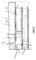
- an otherwise conventional reproduction apparatus or machine system 10 having various of the subject disclosed novel modular and other features, merely by way of one example.
- This disclosed system 10 differs from a conventional reproduction apparatus in that it provides a single platform for an entire family of very different products, by simple modular processor interchanges into common or shared machine elements.
- a common machine frame 11 in which a xerographic monochrome marking or print engine module such as 12 (separately shown in Fig. 5) can be easily extracted and replaced by a color capable ink jet marking engine module such as 14 (separately shown in Fig.
- both modules 12 and 14 slide into the machine 10 from and into the same large opening on the same side of the machine 10.
- the mounting rails 15 here of module 12 are the same as, and spaced the same distance apart as, the mounting rails 15 of module 14, and both are the same distance apart as the mating guides or tracks 16 so that either, but only, modules 12 or 14 can be slid into the same space in the frames 11.
- Other modules may have different guides and/or spacings.
- the illustrated module mounting guides, detents and latchs are merely exemplary, and any of various known slides, slots, hinges, pins, snap connectors or other module mounts may be used.
- either printing engine module 12 and 14 can, when inserted, engage with and share the same entire copy paper input module 17 and its drives (or a separate drive module), the machine 10 controller 100 and its graphic user interface, if any, which may be in a separate ECS module 18 as shown, and various other components.
- the document imager or scanner 19 here is also in a separate removable module, and depending on the selected system 10 configuration, the scanner 19 may be not present at all, or a monochrome scanner module 19a, or a full color scanner 19b.
- a removable document handler module (not shown) may be conventionally provided for either scanner module 19.
- cover units may also be modularly provided, also depending on the desired module combinations and components of the selected configuration and function of the reproduction system 10 for the particular customer.
- the machine frame 11 may also have known detents, such as 22 of Fig. 8, associated with the module mounting guides designed to mate with and hold corresponding mounting elements such as recesses for the detents in the same relative positions on both printing modules 12 and 14.
- Fig. 11 also shows, per se , one example of an module side latching system 23 for fastening modules together in their operative positions.
- a respective electrical connector or multipin plug such as 30, 31, shown in one example in Fig. 9.
- plug 30 of module 12 or plug 31 of module 14 will electrically connect with the same plug connector 32 in the machine 10, such as that shown in Fig. 10, to make power supply connections, control and paper jam detection signals, and other electrical connections with the commonly usable electrical components which remain within the machine 10, especially including the controller 100.
- the connector 32 could be on the machine frame 11 and/or on a mating ECS module such as 19 here.
- the controller 100 can automatically tell which module was inserted from the different electrical connections provided by or through the insertion of plug 30 versus plug 31, and the respective module's connecting circuits. That information can then be used to preset or program the machine 10 appropriately for that particular print module.
- the machine controller 100 can be loaded with two different sets of software, appropriate for the two different print processors 12 or 14, which appropriate software is automatically selected by the insertion of the particular module.
- different software can be loaded into the controller 100 when the different modules are loaded, or the software changes can be on a chip or other memory device on the inserted module itself.
- the xerographic module 12 or the TIJ module 14 it may also be desirable to provide a gear mesh or other mating drive connection in the same relative locations thereon, which upon insertion, mates with another in the machine 10 to provide a drive connection between the module 12 and the paper module 17 drive motor system. That allows the same drive motor system to be used for the entire paper path drive, both upstream of and internally of either module 12 or 14. As noted above, this drive motor can itself be a separately removable, e.g., rear removable, submodule.
- an imaging station or document scanning module 19 preferably also removably mounted to the same machine frame 11 is an imaging station or document scanning module 19.
- the imager module 19 is preferably a known digital document imager so that the same module 19 can provide digital image input to a conventional laser photoreceptor scanner input of the xerographic printing module 12, when that module 12 is in use, or provide digital image input to the ink jet printing module 14 when that module 14 is in use.
- the imaging station 19 module is preferably removed, for cost savings, and a simple blank cover placed in that area.
- the machine 10 base frame unit 11 may have additional integral module mounting guides for the document imaging station module 19, with a separate electronics connector, for operatively connecting this document imaging station module to the respective printing engine module, directly and/or indirectly via the controller 100.
- a different, monochrome, scanner 19a may be desired for a black only printing module 12 than for a plural color printing module 14.
- the xerographic engine module 12 is removable in plural submodules from the base frame unit on plural integral module mounting guides, wherein at least one of these xerographic engine plural submodules is the fuser submodule 50. As shown particularly in Fig. 6 as compared to Fig. 5, the space occupied by the fuser submodule 50 when it is inserted can be used for the ink jet ink tanks 60 and print head or heads 62.
- the xerographic fuser 50 which is of course typically a heated fusing roll or belt system, to remain in the machine 10 even for the ink jet module version or configuration, but to be automatically set up to act dually as a drying element for the back-side of the liquid ink prints as they progress through the same sheet path towards the output tray outside of the reproduction apparatus.
- a different temperature set point may be provided automatically by an automatic software change upon the printing module interchange for effecting that dual function. This provides another optional shared functional tie-in between the two interchanged printing modules in addition to being able to share the same machine frames 11, initial paper path, etc..
- the modularity exchange of the xerographic module 12 (including the fuser) for the ink jet module 14 can most easily occur at the factory or other assembly point, to produce a variety of different products for sale which can easily be altered into different volumes of different configurations to suit customer demands, without requiring tooling or assembly line changes.
- the machine 10 reconfigurations could also by the tech rep installer, especially if different modules are manufactured in different locations or countries and drop shipped directly to customer sites. In some circumstances the desired machine configuration change could also be made or done by the end customer himself, given the simplicity provided here.
- the electronics architecture of the subject machine is preferably designed such that if, for example, a customer originally bought either a xerographic or ink jet based copier per se , and at some later point in time wanted to expand its capabilities to allow it to function as a multifunction device, the customer could go to a retail outlet and buy a modular board add-on to insert to provide the desired increased function(s) .
- Such modular upgrades can variously include fax, direct connect printing, network capable printing, scan to file in various combinations, etc.. They may be insert chips and/or circuit boards inserted in expansion slots in the existing controller 100.
Landscapes
- Physics & Mathematics (AREA)
- General Physics & Mathematics (AREA)
- Accessory Devices And Overall Control Thereof (AREA)
Applications Claiming Priority (2)
| Application Number | Priority Date | Filing Date | Title |
|---|---|---|---|
| US08/777,018 US5850581A (en) | 1997-01-21 | 1997-01-21 | Plural mode modular reproduction apparatus |
| US777018 | 1997-01-21 |
Publications (2)
| Publication Number | Publication Date |
|---|---|
| EP0854399A2 true EP0854399A2 (fr) | 1998-07-22 |
| EP0854399A3 EP0854399A3 (fr) | 2000-02-02 |
Family
ID=25109033
Family Applications (1)
| Application Number | Title | Priority Date | Filing Date |
|---|---|---|---|
| EP98300197A Withdrawn EP0854399A3 (fr) | 1997-01-21 | 1998-01-13 | Dispositif modulaire de reproduction en plusieurs modes |
Country Status (2)
| Country | Link |
|---|---|
| US (1) | US5850581A (fr) |
| EP (1) | EP0854399A3 (fr) |
Cited By (1)
| Publication number | Priority date | Publication date | Assignee | Title |
|---|---|---|---|---|
| EP1621493A3 (fr) * | 2004-07-27 | 2006-04-19 | Rutishauser Data AG | Dispositif d'alimentation en feuilles pour imprimante |
Families Citing this family (20)
| Publication number | Priority date | Publication date | Assignee | Title |
|---|---|---|---|---|
| JP3697010B2 (ja) * | 1997-02-26 | 2005-09-21 | キヤノン株式会社 | 電子写真装置のモジュール連結構造 |
| US6940613B1 (en) * | 1997-04-11 | 2005-09-06 | Xerox Corporation | System for managing replaceable modules in a digital printing apparatus |
| JP2001125332A (ja) * | 1999-06-24 | 2001-05-11 | Ricoh Co Ltd | 画像形成装置 |
| US6304742B1 (en) | 2000-02-24 | 2001-10-16 | Xerox Corporation | Printer with superposed trays for print output and document handling |
| US6350072B1 (en) | 2000-02-24 | 2002-02-26 | Xerox Corporation | Printer with plural mode integral module for document handling print output and print duplex inversion |
| DE10052371A1 (de) * | 2000-10-20 | 2002-05-02 | Schott Glas | Modular aufgebaute elektrofotografische Druckvorrichtung |
| US6868174B2 (en) * | 2000-11-29 | 2005-03-15 | Xerox Corporation | Anti-counterfeit detection for low end products |
| JP2007102188A (ja) * | 2005-09-06 | 2007-04-19 | Canon Inc | 画像形成装置 |
| US7445311B2 (en) | 2005-12-05 | 2008-11-04 | Silverbrook Research Pty Ltd | Printhead maintenance station having maintenance belt |
| US7455383B2 (en) * | 2005-12-05 | 2008-11-25 | Silverbrook Research Pty Ltd | Printhead maintenance station having maintenance belt with belt-cleaning station |
| US7448724B2 (en) * | 2005-12-05 | 2008-11-11 | Silverbrook Research Pty Ltd | Method of maintaining a printhead using a maintenance belt |
| US8364072B2 (en) * | 2008-09-17 | 2013-01-29 | Xerox Corporation | Reconfigurable sheet transport module |
| US8078082B2 (en) * | 2008-12-10 | 2011-12-13 | Xerox Corporation | Modular printing system |
| US8742814B2 (en) | 2009-07-15 | 2014-06-03 | Yehuda Binder | Sequentially operated modules |
| US8602833B2 (en) | 2009-08-06 | 2013-12-10 | May Patents Ltd. | Puzzle with conductive path |
| US9597607B2 (en) | 2011-08-26 | 2017-03-21 | Littlebits Electronics Inc. | Modular electronic building systems with magnetic interconnections and methods of using the same |
| US9019718B2 (en) | 2011-08-26 | 2015-04-28 | Littlebits Electronics Inc. | Modular electronic building systems with magnetic interconnections and methods of using the same |
| US11330714B2 (en) | 2011-08-26 | 2022-05-10 | Sphero, Inc. | Modular electronic building systems with magnetic interconnections and methods of using the same |
| US11616844B2 (en) | 2019-03-14 | 2023-03-28 | Sphero, Inc. | Modular electronic and digital building systems and methods of using the same |
| WO2021096527A1 (fr) * | 2019-11-15 | 2021-05-20 | Hewlett-Packard Development Company, L.P. | Plateaux d'extension |
Family Cites Families (7)
| Publication number | Priority date | Publication date | Assignee | Title |
|---|---|---|---|---|
| GB2132942B (en) * | 1982-09-30 | 1987-07-29 | Canon Kk | Detachable parts of image-forming apparatus |
| GB8715481D0 (en) * | 1987-07-01 | 1987-08-05 | Xerox Corp | Electrostatographic machine |
| US5184178A (en) * | 1988-09-13 | 1993-02-02 | Canon Kabushiki Kaisha | Image recording apparatus having an interchangeable cartridge |
| CA2090642C (fr) * | 1992-05-01 | 1999-06-22 | Thomas N. Taylor | Imprimante xerographique/thermique a jet d'encre combinee |
| JP3087815B2 (ja) * | 1994-04-18 | 2000-09-11 | キヤノン株式会社 | 画像形成装置の構造体 |
| JPH08104034A (ja) * | 1994-10-04 | 1996-04-23 | Canon Inc | 記録装置 |
| DE19513536A1 (de) * | 1995-04-10 | 1996-10-17 | Heidelberger Druckmasch Ag | Druckmaschine mit mehreren Druckwerken |
-
1997
- 1997-01-21 US US08/777,018 patent/US5850581A/en not_active Expired - Fee Related
-
1998
- 1998-01-13 EP EP98300197A patent/EP0854399A3/fr not_active Withdrawn
Cited By (2)
| Publication number | Priority date | Publication date | Assignee | Title |
|---|---|---|---|---|
| EP1621493A3 (fr) * | 2004-07-27 | 2006-04-19 | Rutishauser Data AG | Dispositif d'alimentation en feuilles pour imprimante |
| CH703807B1 (de) * | 2004-07-27 | 2012-03-30 | Rutishauser Data Ag | Druckervorrichtung mit einem Drucker und einer Einzelblatt-Zuführvorrichtung für den Drucker. |
Also Published As
| Publication number | Publication date |
|---|---|
| US5850581A (en) | 1998-12-15 |
| EP0854399A3 (fr) | 2000-02-02 |
Similar Documents
| Publication | Publication Date | Title |
|---|---|---|
| US5850581A (en) | Plural mode modular reproduction apparatus | |
| US5918089A (en) | Modular control assembly for xerographic printer | |
| US6366747B1 (en) | Customizable control panel for a functionally upgradable image printing machine | |
| US8810833B2 (en) | Image processing device and image forming apparatus | |
| JP5394155B2 (ja) | 電子機器及び接続確認方法 | |
| US9316990B2 (en) | Motherboard mounting structure, image forming apparatus and method for performing the same | |
| CN100417171C (zh) | 图像形成设备 | |
| CN110632837B (zh) | 处理盒、以及具备处理盒的图像形成装置 | |
| US11061360B2 (en) | Image forming apparatus | |
| JP2001337499A (ja) | 排紙ユニット及び画像形成装置 | |
| US20090073478A1 (en) | Image forming apparatus | |
| JP5784055B2 (ja) | 画像形成装置及び回路基板 | |
| EP2940533B1 (fr) | Adaptateur de kit d'option et appareil de formation d'image l'utilisant | |
| JP7265920B2 (ja) | 転写ユニットおよび画像形成装置 | |
| CN100409113C (zh) | 具有可配置的打印例行程序的可升级成像系统 | |
| JP3547781B2 (ja) | 画像データ送受信装置 | |
| JP4665662B2 (ja) | 画像形成装置 | |
| US7761029B2 (en) | Image forming apparatus | |
| JP7802572B2 (ja) | 画像形成装置 | |
| JP4538300B2 (ja) | 画像形成装置 | |
| JP2003080797A (ja) | 画像形成装置 | |
| JPS59162573A (ja) | 画像形成装置 | |
| JP2002135471A (ja) | 画像形成装置 | |
| JP6020827B2 (ja) | 消耗品カートリッジ及び画像形成装置 | |
| JP2005043604A (ja) | 画像形成装置 |
Legal Events
| Date | Code | Title | Description |
|---|---|---|---|
| PUAI | Public reference made under article 153(3) epc to a published international application that has entered the european phase |
Free format text: ORIGINAL CODE: 0009012 |
|
| AK | Designated contracting states |
Kind code of ref document: A2 Designated state(s): DE FR GB |
|
| AX | Request for extension of the european patent |
Free format text: AL;LT;LV;MK;RO;SI |
|
| PUAL | Search report despatched |
Free format text: ORIGINAL CODE: 0009013 |
|
| AK | Designated contracting states |
Kind code of ref document: A3 Designated state(s): AT BE CH DE DK ES FI FR GB GR IE IT LI LU MC NL PT SE |
|
| AX | Request for extension of the european patent |
Free format text: AL;LT;LV;MK;RO;SI |
|
| 17P | Request for examination filed |
Effective date: 20000802 |
|
| AKX | Designation fees paid |
Free format text: DE FR GB |
|
| 17Q | First examination report despatched |
Effective date: 20030312 |
|
| STAA | Information on the status of an ep patent application or granted ep patent |
Free format text: STATUS: THE APPLICATION IS DEEMED TO BE WITHDRAWN |
|
| 18D | Application deemed to be withdrawn |
Effective date: 20030723 |