EP0854437A2 - Stellelement mit Schalter - Google Patents
Stellelement mit Schalter Download PDFInfo
- Publication number
- EP0854437A2 EP0854437A2 EP97119487A EP97119487A EP0854437A2 EP 0854437 A2 EP0854437 A2 EP 0854437A2 EP 97119487 A EP97119487 A EP 97119487A EP 97119487 A EP97119487 A EP 97119487A EP 0854437 A2 EP0854437 A2 EP 0854437A2
- Authority
- EP
- European Patent Office
- Prior art keywords
- handle
- adjusting element
- element according
- switch
- switches
- Prior art date
- Legal status (The legal status is an assumption and is not a legal conclusion. Google has not performed a legal analysis and makes no representation as to the accuracy of the status listed.)
- Withdrawn
Links
- 238000005096 rolling process Methods 0.000 claims description 5
- 239000000725 suspension Substances 0.000 claims description 4
- 210000003811 finger Anatomy 0.000 abstract description 3
- 210000003813 thumb Anatomy 0.000 abstract description 2
- 230000005693 optoelectronics Effects 0.000 abstract 1
- 238000009434 installation Methods 0.000 description 3
- 230000004044 response Effects 0.000 description 3
- 230000004048 modification Effects 0.000 description 2
- 238000012986 modification Methods 0.000 description 2
- 208000010428 Muscle Weakness Diseases 0.000 description 1
- 206010028372 Muscular weakness Diseases 0.000 description 1
- 230000004888 barrier function Effects 0.000 description 1
- 238000005452 bending Methods 0.000 description 1
- 230000005540 biological transmission Effects 0.000 description 1
- 230000008859 change Effects 0.000 description 1
- 238000013461 design Methods 0.000 description 1
- 238000006073 displacement reaction Methods 0.000 description 1
- 230000000694 effects Effects 0.000 description 1
- 238000011156 evaluation Methods 0.000 description 1
- 210000003414 extremity Anatomy 0.000 description 1
- 210000001061 forehead Anatomy 0.000 description 1
- 210000003128 head Anatomy 0.000 description 1
- 238000000034 method Methods 0.000 description 1
- 230000003387 muscular Effects 0.000 description 1
- 210000003254 palate Anatomy 0.000 description 1
- 230000008569 process Effects 0.000 description 1
- 230000001953 sensory effect Effects 0.000 description 1
- 238000002560 therapeutic procedure Methods 0.000 description 1
- 210000005182 tip of the tongue Anatomy 0.000 description 1
- 238000012549 training Methods 0.000 description 1
- 210000001364 upper extremity Anatomy 0.000 description 1
Images



Classifications
-
- G—PHYSICS
- G05—CONTROLLING; REGULATING
- G05G—CONTROL DEVICES OR SYSTEMS INSOFAR AS CHARACTERISED BY MECHANICAL FEATURES ONLY
- G05G9/00—Manually-actuated control mechanisms provided with one single controlling member co-operating with two or more controlled members, e.g. selectively, simultaneously
- G05G9/02—Manually-actuated control mechanisms provided with one single controlling member co-operating with two or more controlled members, e.g. selectively, simultaneously the controlling member being movable in different independent ways, movement in each individual way actuating one controlled member only
- G05G9/04—Manually-actuated control mechanisms provided with one single controlling member co-operating with two or more controlled members, e.g. selectively, simultaneously the controlling member being movable in different independent ways, movement in each individual way actuating one controlled member only in which movement in two or more ways can occur simultaneously
- G05G9/047—Manually-actuated control mechanisms provided with one single controlling member co-operating with two or more controlled members, e.g. selectively, simultaneously the controlling member being movable in different independent ways, movement in each individual way actuating one controlled member only in which movement in two or more ways can occur simultaneously the controlling member being movable by hand about orthogonal axes, e.g. joysticks
-
- G—PHYSICS
- G05—CONTROLLING; REGULATING
- G05G—CONTROL DEVICES OR SYSTEMS INSOFAR AS CHARACTERISED BY MECHANICAL FEATURES ONLY
- G05G9/00—Manually-actuated control mechanisms provided with one single controlling member co-operating with two or more controlled members, e.g. selectively, simultaneously
- G05G9/02—Manually-actuated control mechanisms provided with one single controlling member co-operating with two or more controlled members, e.g. selectively, simultaneously the controlling member being movable in different independent ways, movement in each individual way actuating one controlled member only
- G05G9/04—Manually-actuated control mechanisms provided with one single controlling member co-operating with two or more controlled members, e.g. selectively, simultaneously the controlling member being movable in different independent ways, movement in each individual way actuating one controlled member only in which movement in two or more ways can occur simultaneously
- G05G9/047—Manually-actuated control mechanisms provided with one single controlling member co-operating with two or more controlled members, e.g. selectively, simultaneously the controlling member being movable in different independent ways, movement in each individual way actuating one controlled member only in which movement in two or more ways can occur simultaneously the controlling member being movable by hand about orthogonal axes, e.g. joysticks
- G05G2009/0474—Manually-actuated control mechanisms provided with one single controlling member co-operating with two or more controlled members, e.g. selectively, simultaneously the controlling member being movable in different independent ways, movement in each individual way actuating one controlled member only in which movement in two or more ways can occur simultaneously the controlling member being movable by hand about orthogonal axes, e.g. joysticks characterised by means converting mechanical movement into electric signals
-
- H—ELECTRICITY
- H01—ELECTRIC ELEMENTS
- H01H—ELECTRIC SWITCHES; RELAYS; SELECTORS; EMERGENCY PROTECTIVE DEVICES
- H01H25/00—Switches with compound movement of handle or other operating part
- H01H25/04—Operating part movable angularly in more than one plane, e.g. joystick
-
- H—ELECTRICITY
- H01—ELECTRIC ELEMENTS
- H01H—ELECTRIC SWITCHES; RELAYS; SELECTORS; EMERGENCY PROTECTIVE DEVICES
- H01H3/00—Mechanisms for operating contacts
- H01H3/02—Operating parts, i.e. for operating driving mechanism by a mechanical force external to the switch
- H01H3/14—Operating parts, i.e. for operating driving mechanism by a mechanical force external to the switch adapted for operation by a part of the human body other than the hand, e.g. by foot
Definitions
- the invention relates to control elements with switches, such as those used as joysticks or joysticks for computer games, but also as control elements in aircraft or for industrial controls, are in use. They usually have a crunchy grip that the Fist of the operator is grasped, and at least on the free end in a sloping surface a pressure switch to be operated with the ladies. An erroneous axial stress on the Handle, for example, by a support movement of the operator's hand, leads uncontrollably to unwanted and therefore later hardly reproducible control processes.
- the actuator usually responds depending on the path, namely comparatively large swivel paths to Adjustment of potentiometers, for actuating switch contacts or for deforming Expansion or bending sensors, this also has the disadvantageous consequence that the switch position is variable relative to the location of the joystick. Because of this path dependency is one conventional actuating element hardly suitable for operation by the handicapped; especially due to muscle weakness, which in itself are hardly able to handle larger arm and Execute hand movements specifically and reproducibly, let alone under direction-defined Applying force via the movement path. A conscious switch operation on a deflecting Handle is therefore often no longer feasible for them.
- the present invention is based on the task of a to design the control element of the generic type, which is equipped with a switch, in such a way that a targeted, reproducible operation even by extremely handicapped people becomes.
- the actuating element 11 sketched in an oblique view in FIG. 1 is in or under an also as a support for the hand 12 of the operator serving cover plate 13 is mounted, from which a rod-shaped handle 14 towering. It runs parallel to a not so towering, rigid with the Control element 11 or the cover plate 13 connected bracket 15 for tactile switches 16, which selectively operated by fingertips of the hand 12 by pressure across the longitudinal axis handle 14 can be.
- the switches 16 can be sketched on the bracket 15 with respect to their Longitudinal axis are azimuthally and / or longitudinally offset from one another. Sufficient in the interest Installation volume and good accessibility can, according to FIG Bracket 15 can be provided, which thus the handle 14 tubular but axially parallel eccentric surrounds.
- the switches 16 can have any function, for example implemented as electromechanical microswitches, as optronic light barriers, as binary responsive pressure sensors, as continuous responsive pressure sensors with binary switching threshold evaluation mg or e.g. also as magnetic field switching paths. With their switching behavior, they preferably speak to a minimum Stroke or other extremely small tactile influence (such as displacement of a magnet or shading a photodetector). Now there is practically no risk of incorrect operation, because the operator's hand 12 is stationary with respect to the actuating element 11 Switches 16 are at rest, so no movements of a handle 14 have to follow. It can on her free, via which e.g.
- tubular bracket 15 axially projecting end 17 between the thumb and index finger of the operator's hand 12 are gripped and subjected to transverse pressure, without thereby swinging out noticeably from their rest position, because this adjusting element 11 is practical works without a path.
- This area of attack 18 under the front end 17 of the handle 14 also contrary to the illustration in FIG. 1 in comparison to the adjacent area of the switch holder 15 have a larger or the same cross-sectional dimension, cf. Fig.2 to the tactile Assignment between handle 14 with analog response and switch 16 with binary response to be able to differentiate better.
- the ohmic or sensory switching paths 19 are expediently influenced Via a lever 20 with little travel, as in Fig. 2/3 as a basic example for the circumference of the holder 15
- One-arm levers 20 running peripherally offset from one another are shown.
- the axial exit of the handle 14 from the holder 15 are in the radial Direction with respect to the switch bracket 15 and thus parallel to the application of force Analog handle 14 free lever ends to be operated 21.
- the restoring force is by a pressure spring deposited on the lever 20, preferably by the respective against the Housing 23 radially supported switching path 19 itself exercised.
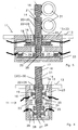
- FIG. 2 From the axial longitudinal section of FIG. 2 it can also be seen how the handle 14 below minimal radial play concentrically through a tubular holder 15 - for the recording the switch 16 and their actuation levers 20 - concentrically or eccentrically through axially parallel can run.
- the handle suspended in a rolling element joint 24 as a fulcrum 14 in turn is part of a two-armed lever 26.
- Its second lever arm carries beyond the rolling element suspension 24 a tare weight 25 for indifferent equilibrium Handle 14 in every spatial installation position of the actuating element 11 in order to determine its response behavior independent of the installation position and insensitive to structure-borne noise.
- each of circular cross section, and a rigid transmission plate 28 is the actuating lever 26 free of play against at least one practically pathless analog responsive Pressure sensor 29, which is rigidly supported against the housing 23, so that a transverse load on the Handle 14 does not lead to a remarkable deflection in the tube 15.
- the binary responsive switches 16 are in the housing 23 laid in and therein according to the analog sensors 29 for stress again arranged radially with respect to the longitudinal axis of the housing 23. It can also be in the neighborhood the handle 14 arranged in the housing 23 serve as a switch 16 by the sensors have a potential-controlled switching stage (a Schmitt trigger or a similar one Query circuit with pronounced tipping behavior) follows.
- a potential-controlled switching stage a Schmitt trigger or a similar one Query circuit with pronounced tipping behavior
- the levers 20 are now, so to speak combined into a tube 30, which is concentric outside the handle 14 in the housing 23 dips into it, which thus now directly assumes the support function of the holder 15
- a bearing 22 for a now two-armed switch lever 20
- Rolling bearing suspension 24 (roller-shaped for a diametrical switch pair 16-16 or spherical for two orthogonally arranged switch pairs 16-16). Guaranteed here too an indifferent balance by means of a counterweight 25 to the long arm of the lever tube 30 a practically position and vibration-proof switch actuation.
- the attack area 18 at the front end 17 of the handle 14 is designed as a mouthpiece to the actuating element 11, for example for computer input or for controlling a self-propelled medical elevator to be able to be operated by disabled people who no longer have limbs dispose of it.
- the actuation of the actuating element 11 now takes place in that the front end 17 clamped between the lips and the head 33 is moved. Involuntarily occurring Axial pressure components have no effect on the input, since the handle 14 in the The pivot point of the joint 24 is axially rigidly suspended.
- the operating lever 20 for the switching path 16 is now oriented transversely to the longitudinal axis of the handle 14, approximately as one that passes through Mouthpiece 18 surrounding ring 34.
- this handle 14 over a part of its length with little radial play surrounded by a tubular holder 15 for binary responsive switches 16, this bracket 15 as a support for the switch actuation rigid with the housing 23 of the control element 11 is connected and bearings 22/24 for switch actuating lever 20/30/34 can have the levers 20 can also be combined into a tube 30, that like the handle 14 as a two-armed lever on a rolling element suspension 24 in the indifferent Equilibrium protrudes into the actuator housing 23, in the switch 16 parallel to the Pressure sensors 28 are arranged.
- the switch operating lever 20 is a before Forehead of the bracket 15 mounted ring 34 when the handle 14 passing through for operation to be taken as a mouthpiece 18 between the lips. In all cases, the switches are 16 decoupled from the handle 14 but still operable in the immediate vicinity.
Landscapes
- Physics & Mathematics (AREA)
- General Physics & Mathematics (AREA)
- Engineering & Computer Science (AREA)
- Automation & Control Theory (AREA)
- Mechanical Control Devices (AREA)
- Switches With Compound Operations (AREA)
Abstract
Description
- Fig.1
- einen querschittsunsymmetrischen koaxialen Aufbau eines ersten Realisierungsbeispieles für ein mit radial zu betätigenden Schaltern ausgestattetes Stellelement nach vorliegender Erfindung in Schrägansicht,
- Fig.2
- ein querschnittssymmetrisches es solches Stellelement mit Schalter-Hebeln im Axial-Längsschnitt,
- Fig.3
- das Stellelement gemäß Fig.2 im Querschnitt,
- Fig.4
- ein Stellelement mit gegenüber Fig.2 abgewandelter Anordnung der Schalter,
- Fig.5
- eine weitere Abwandlung gegenüber Ausbildung nach Fig.2 und
- Fig.6
- im Axial-Längsschnitt einen mit den Lippen zu betätigenden Schalter an einem mit dem Munde zu bedienenden Stellelement.
Claims (10)
- Stellelement (11) mit Schalter (16), dadurch gekennzeichnet, daß wenigstens ein taktiler Schalter (16) an einer bezüglich des Gehäuses (23) Stellelementes (11) stationären Halterung (15) angeordnet ist, die wenigstens bereichsweise parallel zu einer praktisch weglos ansprechenden Handhabe (14) für Beeinflussung von Stellelement-Sensoren (28) verläuft.
- Stellelement nach Anspruch 1, dadurch gekennzeichnet, daß die Halterung (15) eine axial gestreckte Handhabe (14) rohrförmig umgibt.
- Stellelement nach Anspruch 1 oder 2, dadurch gekennzeichnet, daß Schalter (16) an der Außenmantelfläche der Halterung (15) betätigbar sind.
- Stellelement nach einem der vorangehenden Ansprüche, dadurch gekennzeichnet, daß wenigstens ein etwa achsparallel zur Handhabe (14) verlaufender Hebel (20) für die Betätigung wenigstens eines Schalters (16) vorgesehen ist.
- Stellelement nach Anspruch 4, dadurch gekennzeichnet, daß in der Außenmantelfläche der Halterung (15) einarmige Hebel (20) angeordnet sind.
- Stellelement nach Anspruch 4 oder 5, dadurch gekennzeichnet, daß ein rohrförmiger Hebel (30) für mehrere peripher gegeneinander versetzte Schalter (16) vorgesehen ist.
- Stellelement nach Anspruch 6, dadurch gekennzeichnet, daß die Halterung (15) in sein Gehäuse (23) hinein verlegt ist, in das ein zweiarmige Hebel (Rohr 30) über eine Wälzkörper-Aufhängung (24) hineinragt.
- Stellelement nach Anspruch 7, dadurch gekennzeichnet, daß der in das Gehäuse (23) hineinragende Arm des Hebels (30) durch ein Gewicht (25) auf indifferentes Gleichgewicht austariert ist.
- Stellelement nach einem der vorangehenden Ansprüche, dadurch gekennzeichnet, daß die aus der rohrförmigen Schalter-Halterung (15) axial hervorragende Handhabe (14) mit einem aufgedickten Griffbereich (18) ausgestattet ist.
- Stellelement nach Anspruch 9, dadurch gekennzeichnet, daß der Griffbereich (18) als Mundstück ausgebildet ist.
Applications Claiming Priority (4)
| Application Number | Priority Date | Filing Date | Title |
|---|---|---|---|
| DE19647148 | 1996-11-14 | ||
| DE19647148A DE19647148A1 (de) | 1996-05-28 | 1996-11-14 | Stellelement mit Schalter |
| DE29710446U DE29710446U1 (de) | 1996-11-14 | 1997-06-17 | Stellelement mit Schalter |
| DE29710446U | 1997-06-17 |
Publications (2)
| Publication Number | Publication Date |
|---|---|
| EP0854437A2 true EP0854437A2 (de) | 1998-07-22 |
| EP0854437A3 EP0854437A3 (de) | 2002-11-13 |
Family
ID=26031292
Family Applications (1)
| Application Number | Title | Priority Date | Filing Date |
|---|---|---|---|
| EP97119487A Withdrawn EP0854437A3 (de) | 1996-11-14 | 1997-11-07 | Stellelement mit Schalter |
Country Status (1)
| Country | Link |
|---|---|
| EP (1) | EP0854437A3 (de) |
Cited By (4)
| Publication number | Priority date | Publication date | Assignee | Title |
|---|---|---|---|---|
| EP1297801A1 (de) * | 2001-10-01 | 2003-04-02 | ARC Seibersdorf research GmbH | Steuereinheit |
| US6580414B1 (en) | 1998-10-19 | 2003-06-17 | Gerhard Wergen | Method for transferring characters especially to a computer and an input device which functions according to this method |
| EP3069957A1 (de) * | 2015-03-18 | 2016-09-21 | 't Tilcentrum B.V. | Betätigungsvorrichtung und patiententransportvorrichtung mit solch einer betätigungsvorrichtung |
| FR3134310A1 (fr) | 2022-04-08 | 2023-10-13 | Hitclic | Dispositif de commande, notamment pour jeux video, actionnable avec le menton et/ou avec la bouche d’une personne |
Citations (1)
| Publication number | Priority date | Publication date | Assignee | Title |
|---|---|---|---|---|
| DE29609458U1 (de) | 1995-06-02 | 1996-12-05 | Wergen, Gerhard, Dipl.-Ing., 90513 Zirndorf | Analoges Stellelement |
Family Cites Families (4)
| Publication number | Priority date | Publication date | Assignee | Title |
|---|---|---|---|---|
| FR2332568A1 (fr) * | 1975-11-20 | 1977-06-17 | Thevenot Louis | Dispositif d'actionnement pour tetraplegiques et infirmes analogues |
| US4367373A (en) * | 1981-04-07 | 1983-01-04 | The United States Of America As Represented By The Secretary Of The Air Force | Two-axis electromechanical controller |
| US4488017A (en) * | 1983-02-07 | 1984-12-11 | Amiga Corporation | Control unit for video games and the like |
| GB8619608D0 (en) * | 1986-08-12 | 1986-09-24 | Britannia Software Ltd | Computer control devices |
-
1997
- 1997-11-07 EP EP97119487A patent/EP0854437A3/de not_active Withdrawn
Patent Citations (1)
| Publication number | Priority date | Publication date | Assignee | Title |
|---|---|---|---|---|
| DE29609458U1 (de) | 1995-06-02 | 1996-12-05 | Wergen, Gerhard, Dipl.-Ing., 90513 Zirndorf | Analoges Stellelement |
Cited By (4)
| Publication number | Priority date | Publication date | Assignee | Title |
|---|---|---|---|---|
| US6580414B1 (en) | 1998-10-19 | 2003-06-17 | Gerhard Wergen | Method for transferring characters especially to a computer and an input device which functions according to this method |
| EP1297801A1 (de) * | 2001-10-01 | 2003-04-02 | ARC Seibersdorf research GmbH | Steuereinheit |
| EP3069957A1 (de) * | 2015-03-18 | 2016-09-21 | 't Tilcentrum B.V. | Betätigungsvorrichtung und patiententransportvorrichtung mit solch einer betätigungsvorrichtung |
| FR3134310A1 (fr) | 2022-04-08 | 2023-10-13 | Hitclic | Dispositif de commande, notamment pour jeux video, actionnable avec le menton et/ou avec la bouche d’une personne |
Also Published As
| Publication number | Publication date |
|---|---|
| EP0854437A3 (de) | 2002-11-13 |
Similar Documents
| Publication | Publication Date | Title |
|---|---|---|
| EP0829066B1 (de) | Analoges stellelement | |
| DE68906751T2 (de) | Handsteuervorrichtung. | |
| DE602004006227T2 (de) | Benutzerschnittstellenvorrichtung | |
| DE69402079T2 (de) | Steuervorrichtung mit steuerknüppel insbesondere miniknüppel zum steuern eines luftfahrzeuges | |
| DE69927894T2 (de) | Schaltknüppel | |
| WO2007009744A2 (de) | Bedienelement mit kipphaptik | |
| EP3620584B1 (de) | Bedienteil für eine fernsteuerung, umfassend einen aktivierungssensor mit veränderbarem effektiven sensorbereich | |
| DE29515312U1 (de) | Steuerknüppel | |
| DE19712048A1 (de) | Bedienvorrichtung | |
| EP2086490B1 (de) | Ärztliche Behandlungsvorrichtung mit einem Sensorhandgriff | |
| DE10303860A1 (de) | Konstruktion von Bremspedalen | |
| DE29710446U1 (de) | Stellelement mit Schalter | |
| DE102008033365A1 (de) | Bedienelement zur Einhandbedienung ophtalmologischer Geräte | |
| DE3427416A1 (de) | Betaetigungseinrichtung mit einem durch fusswinkelbewegungen zu betaetigenden bedienmittel | |
| DE19647148A1 (de) | Stellelement mit Schalter | |
| DE10347733A1 (de) | Motorisch verstellbares Röntgengerät | |
| DE19740526C1 (de) | Betätigungsvorrichtung, insbesondere für Lenkstockhebel in Kraftfahrzeugen, zur Realisierung von Schaltfunktionen und Verfahren zur Anwendung einer solchen Betätigungsvorrichtung | |
| DE102024102583A1 (de) | Bedieneinheit für ein Fahrzeug | |
| EP1219562A2 (de) | Vorrichtung zur Handsteuerung, insbesondere eines Fahr-und/oder Hubantriebs einer Lasthebevorrichtung | |
| AT412745B (de) | Steuereinheit | |
| DE2917817C2 (de) | Pneumatischer Membranantrieb mit pneumatischem Stellungsregler | |
| EP0854437A3 (de) | Stellelement mit Schalter | |
| DE10012436A1 (de) | Stellelement | |
| DE10043566B4 (de) | Trainingsgerät für Bewegungsbehinderte | |
| EP1142617A1 (de) | Steuereinrichtung mit einem oder mehreren Armen zum Steuern eines Geräts oder eines Computers |
Legal Events
| Date | Code | Title | Description |
|---|---|---|---|
| PUAI | Public reference made under article 153(3) epc to a published international application that has entered the european phase |
Free format text: ORIGINAL CODE: 0009012 |
|
| AK | Designated contracting states |
Kind code of ref document: A2 Designated state(s): AT BE CH DE DK ES FI FR GB GR IE IT LI LU MC NL PT SE |
|
| AX | Request for extension of the european patent |
Free format text: AL;LT;LV;MK;RO;SI |
|
| PUAL | Search report despatched |
Free format text: ORIGINAL CODE: 0009013 |
|
| AK | Designated contracting states |
Kind code of ref document: A3 Designated state(s): AT BE CH DE DK ES FI FR GB GR IE IT LI LU MC NL PT SE |
|
| AX | Request for extension of the european patent |
Free format text: AL;LT;LV;MK;RO;SI |
|
| RIC1 | Information provided on ipc code assigned before grant |
Free format text: 7G 05G 9/047 A, 7G 05G 1/20 B |
|
| 17P | Request for examination filed |
Effective date: 20021129 |
|
| AKX | Designation fees paid | ||
| REG | Reference to a national code |
Ref country code: DE Ref legal event code: 8566 |
|
| STAA | Information on the status of an ep patent application or granted ep patent |
Free format text: STATUS: THE APPLICATION IS DEEMED TO BE WITHDRAWN |
|
| 18D | Application deemed to be withdrawn |
Effective date: 20020601 |