EP0854457A1 - Türverriegelung - Google Patents
Türverriegelung Download PDFInfo
- Publication number
- EP0854457A1 EP0854457A1 EP97121199A EP97121199A EP0854457A1 EP 0854457 A1 EP0854457 A1 EP 0854457A1 EP 97121199 A EP97121199 A EP 97121199A EP 97121199 A EP97121199 A EP 97121199A EP 0854457 A1 EP0854457 A1 EP 0854457A1
- Authority
- EP
- European Patent Office
- Prior art keywords
- door
- lock
- locking
- machine
- vending machine
- Prior art date
- Legal status (The legal status is an assumption and is not a legal conclusion. Google has not performed a legal analysis and makes no representation as to the accuracy of the status listed.)
- Granted
Links
- 238000013475 authorization Methods 0.000 description 1
- 238000006073 displacement reaction Methods 0.000 description 1
- 238000005553 drilling Methods 0.000 description 1
- 238000003780 insertion Methods 0.000 description 1
- 230000037431 insertion Effects 0.000 description 1
- 239000002184 metal Substances 0.000 description 1
- 238000000034 method Methods 0.000 description 1
- 239000007787 solid Substances 0.000 description 1
Images


Classifications
-
- G—PHYSICS
- G07—CHECKING-DEVICES
- G07F—COIN-FREED OR LIKE APPARATUS
- G07F9/00—Details other than those peculiar to special kinds or types of apparatus
- G07F9/10—Casings or parts thereof, e.g. with means for heating or cooling
-
- E—FIXED CONSTRUCTIONS
- E05—LOCKS; KEYS; WINDOW OR DOOR FITTINGS; SAFES
- E05C—BOLTS OR FASTENING DEVICES FOR WINGS, SPECIALLY FOR DOORS OR WINDOWS
- E05C19/00—Other devices specially designed for securing wings, e.g. with suction cups
- E05C19/006—Other devices specially designed for securing wings, e.g. with suction cups by displacement of the wing substantially in its own plane
-
- E—FIXED CONSTRUCTIONS
- E05—LOCKS; KEYS; WINDOW OR DOOR FITTINGS; SAFES
- E05F—DEVICES FOR MOVING WINGS INTO OPEN OR CLOSED POSITION; CHECKS FOR WINGS; WING FITTINGS NOT OTHERWISE PROVIDED FOR, CONCERNED WITH THE FUNCTIONING OF THE WING
- E05F7/00—Accessories for wings not provided for in other groups of this subclass
- E05F7/02—Accessories for wings not provided for in other groups of this subclass for raising wings before being turned
-
- E—FIXED CONSTRUCTIONS
- E05—LOCKS; KEYS; WINDOW OR DOOR FITTINGS; SAFES
- E05Y—INDEXING SCHEME ASSOCIATED WITH SUBCLASSES E05D AND E05F, RELATING TO CONSTRUCTION ELEMENTS, ELECTRIC CONTROL, POWER SUPPLY, POWER SIGNAL OR TRANSMISSION, USER INTERFACES, MOUNTING OR COUPLING, DETAILS, ACCESSORIES, AUXILIARY OPERATIONS NOT OTHERWISE PROVIDED FOR, APPLICATION THEREOF
- E05Y2999/00—Subject-matter not otherwise provided for in this subclass
Definitions
- the invention relates to a lock for the door of a vending machine.
- vending machines In the interior of vending machines, the goods to be sold as well the money received or, if necessary, also change is stored. For filling and maintaining such a vending machine is generally one entire door of the vending machine covering door is provided. This door must be secured against unauthorized opening.
- the invention has for its object a lock for the door Train vending machines in such a way that they improve Protection against unauthorized opening, d. H. improved burglary protection having.
- This object is achieved in that the door parallel to when closing Front of the vending machine is moved, being on the edges locking means arranged in accordance with the inside of the door trained recesses / receptacles in the (front) part of the frame Intervene in vending machines and lock the door on all sides, and that a locking element is provided, which in its locked position Moving the door prevented.
- the forces to be applied for the locking actuation which are quite high per se, can be achieved by means of a stable lever, wherein only a small, easy-to-operate lock with a corresponding key is required to lock the locking mechanism.
- this lock is then provided in a version protected against drilling. Since, according to the invention, the actuating forces for the locking no longer have to be applied directly from the lock or key, there is also no longer any danger of the key being broken in the case of locked interlocks in external machines.
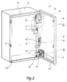
- a vending machine is shown, the door of which is open in FIG. 2.
- the vending machine essentially consists of a box-shaped housing 1, the front of which is provided with a door 2.
- goods selection means In the front of the door, goods selection means, a coin input opening and a goods output opening 5 are provided in a known manner.
- the door is attached to the housing by means of hinges 6.
- the pins 7 of the hinges are so long that lifting the door, ie moving the door in the vertical direction, is possible without the hinges being separated.
- the inside of the door is provided on its left side, opposite the hinge side, with locking means 8 designed as latching hooks. On the hinge side of the door locking means 8 'are also provided on the housing as locking hooks.
- the locking means 8 are immersed in recesses 9 in the frame part of the housing when the door is closed, and the locking means 8 'are immersed in recesses 9' which are provided in solid metal sheets fastened to the inside of the door when the door is closed.
- Trough-shaped receptacles 11, 11 ' are provided on the upper and lower frame part of the housing and interact with locking means 12, 12' formed at the upper and lower ends of the door when the door is closed / locked.
- the door that is initially opened is pivoted about the hinge's axis of rotation until it is parallel to the front of the housing.
- the locking means 8, 8 'dip into the corresponding recesses 9, 9', and the locking means 12, 12 'of the door are located above the receptacles 11, 11' of the frame.
- the entire door is then lowered by means of a lever mechanism, which will be explained further below, ie it is moved parallel to the front of the housing.
- the front ends of the locking hooks get behind the lower edge areas of the recesses, and the bevels of the door get into the corresponding receptacles on the frame of the housing.
- the door is then positively locked on all sides, ie pivoting of the door in the opening direction is no longer possible.
- a locking bolt 13 is slidably attached to the door and is pushed into a correspondingly assigned receiving recess 14 in the frame of the housing. Possibly. can be provided that the locking bolt can be actuated electromagnetically or by motor.
- the lever mechanism 15 shown in FIGS. 3 and 4 is provided for lifting and lowering the door.
- the lever mechanism essentially consists of a base plate 16 fastened to the door 2, on which levers 17, 18, 19 connected to one another via joints are provided.
- the lower lever 17 is provided with a projection 20 pointing towards the outside of the machine, which has a recess for the positive reception / insertion of an Allen key-like actuating lever 21.
- the lever 17 can be pivoted by means of this lever 21, the levers 18, 19 connected via rotary joints also being pivoted. Ultimately, the end 22 of the lever 19 is moved up or down.
- a key-operated lock 24 is provided in the base plate, the eccentrically arranged pin 25 of which acts on the locking bolt 13 and moves it into its open or closed position.
- a further pin 26 is provided on the locking bolt, which projects through the base plate and acts on a rotatably fastened striking plate 27. The arrangement is such that in the closed state of the door, ie with the door lowered and the locking bolt moved into its closed position, the opening 28 in the door 2 for inserting the actuating lever 21 is closed / covered by the striking plate.
- the assignment of the locking hooks and recesses to the door or the housing can possibly also be changed / swapped. Is essential only that there is always a locking hook with a corresponding recess cooperates. Also, the top and bottom of the door do not have to be bent and the housing with appropriate receptacles. Also on the upper and lower side of the door and housing Snap hooks and corresponding recesses may be provided.
- the arrangement of the hinges of the door ie their axis of rotation, can also be seen only as an example.
- the hinges can optionally also be provided on the top of the door, but then a transverse displacement of the door must be provided for locking or unlocking. It is essential that the door can be moved parallel to the front of the machine.
Landscapes
- Physics & Mathematics (AREA)
- General Physics & Mathematics (AREA)
- Engineering & Computer Science (AREA)
- Mechanical Engineering (AREA)
- Control Of Vending Devices And Auxiliary Devices For Vending Devices (AREA)
- Vending Machines For Individual Products (AREA)
- Lock And Its Accessories (AREA)
Abstract
Description
Da die Betätigungskräfte für die Verriegelung erfindungsgemäß nicht mehr direkt vom Schloß bzw. Schlüssel aufgebracht werden müssen, ist auch die Gefahr des Schlüsselbruchs bei etwa eingefrorenen Verriegelungen bei Außenautomaten nicht mehr vorhanden.
- Fig. 1
- die Ansicht eines Warenautomaten,
- Fig. 2
- die Ansicht des Warenautomaten mit geöffneter Tür, und
- Fig. 3 und 4
- die Ansichten eines Hebelmechanismus.
Der Warenautomat besteht im wesentlichen aus einem kastenförmigen Gehäuse 1, dessen Vorderseite mit einer Tür 2 versehen ist.
In der Vorderseite der Tür sind in bekannter Art und Weise Warenauswahlmittel, eine Münzeingabeöffnung sowie eine Warenausgabeöffnung 5 vorgesehen.
Die Tür ist mittels Scharnieren 6 an dem Gehäuse befestigt. Dabei sind die Zapfen 7 der Scharniere so lang ausgebildet, daß ein Anheben der Tür, d. h. eine Verschiebung der Tür in senkrechter Richtung möglich ist, ohne daß die Scharniere getrennt werden.
Weiterhin ist die Tür auf ihrer Innenseite an ihrer linken, der Scharnierseite gegenüberliegenden Seite mit als Rasthaken ausgebildeten Verriegelungsmitteln 8 versehen. Auf der Scharnierseite der Tür sind am Gehäuse ebenfalls als Rasthaken ausgebildete Verriegelungsmittel 8' vorgesehen. Die Verriegelungsmittel 8 tauchen beim Schließen der Tür in Ausnehmungen 9 im Rahmenteil des Gehäuses ein, und die Verriegelungsmittel 8' tauchen beim Schließen der Tür in Ausnehmungen 9' ein, die in an der Türinnenseite befestigten, massiven Blechen vorgesehen sind.
Am oberen und unteren Rahmenteil des Gehäuses sind rinnenförmige Aufnahmen 11, 11' vorgesehen, die mit am oberen bzw. unteren Ende der Tür durch Abkantungen gebildete Verriegelungsmittel 12, 12' beim Schließen/Verriegeln der Tür zusammenwirken.
Anschließend wird die gesamte Tür mittels eines weiter unten noch erläuterten Hebelmechanismus abgesenkt, d. h. parallel zur Vorderseite des Gehäuses verschoben. Dabei gelangen die vorderen Enden der Rasthaken hinter die unteren Randbereiche der Ausnehmungen, und die Abkantungen der Tür gelangen in die jeweils entsprechenden Aufnahmen am Rahmen des Gehäuses. Danach ist die Tür allseitig formschlüssig verriegelt, d. h. ein Schwenken der Tür in Öffnungsrichtung ist nicht mehr möglich.
Um die Tür abzuschließen, d. h. ein unbefugtes Anheben und Öffnen zu verhindern, ist ein an der Tür verschiebbar befestigter Riegelbolzen 13 vorgesehen, der in eine entsprechend zugeordnete Aufnahmeausnehmung 14 im Rahmen des Gehäuses geschoben wird. Ggf. kann vorgesehen sein, daß der Riegelbolzen elektromagnetisch oder motorisch betätigbar ist.
Der Hebelmechanismus besteht im wesentlichen aus einer an der Tür 2 befestigten Grundplatte 16, an der über Gelenke miteinander verbundene Hebel 17, 18, 19 vorgesehen sind. Der untere Hebel 17 ist mit einem zur Automatenaußenseite weisenden Ansatz 20 versehen, der eine Ausnehmung zur formschlüssigen Aufnahme / zum Einstecken eines Imbus-schlüsselartigen Betätigungshebels 21 aufweist.
Durch diesen Hebel 21 kann der Hebel 17 verschwenkt werden, wobei die über Drehgelenke verbundenen Hebel 18, 19 ebenfalls verschwenkt werden. Letztendlich wird das Ende 22 des Hebels 19 nach oben oder unten bewegt. Dieses Ende liegt auf einem Ansatz 23 des Gehäuserahmens auf, und bei Bewegung des Endes nach unten wird die Tür so weit angehoben, daß die Verriegelungsmittel 8, 8', 9, 9', 11, 11', 12, 12' außer Eingriff gelangen und die Tür geschwenkt/geöffnet werden kann.
Schließlich ist in der Grundplatte noch ein schlüsselbetätigbares Schloß 24 vorgesehen, dessen exzentrisch angeordneter Zapfen 25 auf den Riegelbolzen 13 wirkt und diesen in seine Offen- oder Schließstellung bewegt.
Am Riegelbolzen ist ein weiterer Zapfen 26 vorgesehen, der durch die Grundplatte ragt und auf ein drehbeweglich befestigtes Schließblech 27 einwirkt. Dabei ist die Anordnung so getroffen, daß in abgeschlossenem Zustand der Tür, d. h. bei abgesenkter Tür und in seine Schließstellung verschobenem Riegelbolzen, die Öffnung 28 in der Tür 2 zum Einführen des Betätigungshebels 21 durch das Schließblech verschlossen/abgedeckt ist.
Wesentlich ist, daß die Tür parallel zur Automatenvorderseite verschiebbar ist.
Claims (9)
- Verriegelung für die Tür eines Warenautomaten, dadurch gekennzeichnet,daß die Tür (2) beim Schließen parallel zur Vorderseite des Warenautomaten verschoben wird, wobei an den Rändern der Innenseite der Tür angeordnete Verriegelungsmittel (8, 8', 12, 12') in entsprechend ausgebildete Ausnehmungen (9, 9')/ Aufnahmen (11, 11') im (vorderen) Rahmenteil des Warenautomaten eingreifen und die Tür (2) allseitig formschlüssig verriegeln, unddaß ein Sperrelement (13) vorgesehen ist, das in seiner Sperrstellung ein Verschieben der Tür verhindert.
- Verriegelung nach Anspruch 1, dadurch gekennzeichnet,daß zum Verschieben der Tür ein Hebelmechanismus (15) vorgesehen ist, der von der Außenseite des Warenautomaten betätigbar ist.
- Verriegelung nach Anspruch 2, dadurch gekennzeichnet,daß die Betätigungsmöglichkeit des Hebelmechanismus (15) durch ein Schloß (24) in der Automatenaußenseite abschließbar ist.
- Verriegelung nach Anspruch 2, dadurch gekennzeichnet,daß die Betätigung des Hebelmechanismus (15) durch einen in eine Öffnung (28) in der Automatenaußenseite einsteckbaren Betätigungshebel (21) erfolgt.
- Verriegelung nach Anspruch 4, dadurch gekennzeichnet,daß die Öffnung (28) in der Automatenaußenseite durch ein Steckschloß o.ä. verschließbar ist.
- Verriegelung nach Anspruch 4, dadurch gekennzeichnet,daß die Öffnung (28) in der Automatenaußenseite durch ein Verschlußblech (27) abdeckbar/verschließbar ist, das durch das schlüsselbetätigbare Schloß (24) in Verbindung mit einem entsprechenden Hebelwerk verschiebbar ist.
- Verriegelung nach Anspruch 6, dadurch gekennzeichnet,daß das Schloß (24) auf das Sperrelement (13) einwirkt, das die Tür in ihrer geschlossenen Stellung verriegelt.
- Verriegelung nach Anspruch 7, dadurch gekennzeichnet,daß das Sperrelement (13) als Riegelbolzen ausgebildet ist, der beiabgeschlossener" Tür in eine entsprechende Öffnung (14) im Automatengehäuse eintaucht.

- Verriegelung nach einem oder mehreren der vorstehenden Ansprüche, dadurch gekennzeichnet,daß das Sperrelement (13) elektromechanisch oder motorisch betätigbar ist.
Applications Claiming Priority (2)
| Application Number | Priority Date | Filing Date | Title |
|---|---|---|---|
| DE19701047A DE19701047C1 (de) | 1997-01-15 | 1997-01-15 | Türverriegelung |
| DE19701047 | 1997-01-15 |
Publications (2)
| Publication Number | Publication Date |
|---|---|
| EP0854457A1 true EP0854457A1 (de) | 1998-07-22 |
| EP0854457B1 EP0854457B1 (de) | 2002-02-27 |
Family
ID=7817365
Family Applications (1)
| Application Number | Title | Priority Date | Filing Date |
|---|---|---|---|
| EP97121199A Expired - Lifetime EP0854457B1 (de) | 1997-01-15 | 1997-12-03 | Türverriegelung |
Country Status (3)
| Country | Link |
|---|---|
| EP (1) | EP0854457B1 (de) |
| AT (1) | ATE213858T1 (de) |
| DE (2) | DE19701047C1 (de) |
Cited By (5)
| Publication number | Priority date | Publication date | Assignee | Title |
|---|---|---|---|---|
| FR2828906A1 (fr) | 2001-08-23 | 2003-02-28 | Georges Koussouros | Barriere anti intrusion |
| FR2837859A1 (fr) * | 2002-03-27 | 2003-10-03 | Cibox | Portillon de securite notamment pour boites, cases et coffres |
| DE202009000767U1 (de) | 2009-01-21 | 2009-04-16 | Mk Electronic E.K. Mike Kleene | Warenverkaufsautomat mit einem einbruchgesicherten Geldbereich |
| ITBO20090370A1 (it) * | 2009-06-05 | 2010-12-06 | Valford S R L | Dispositivo di sicurezza per casseforti e simili. |
| EP2258635A3 (de) * | 2009-06-01 | 2012-06-27 | Glasdon Group Limited | Müllbehälter mit einer Zugangstür |
Families Citing this family (1)
| Publication number | Priority date | Publication date | Assignee | Title |
|---|---|---|---|---|
| DE202017103716U1 (de) | 2017-06-14 | 2017-08-14 | S&Z Elektronik GmbH | Verkaufsautomat |
Citations (8)
| Publication number | Priority date | Publication date | Assignee | Title |
|---|---|---|---|---|
| US1698252A (en) * | 1927-03-12 | 1929-01-08 | Marselius T Ashe | Inclosure |
| US2069233A (en) * | 1934-01-06 | 1937-02-02 | Motor Terminals Co | Door locking mechanism for freight containers |
| DE1449297A1 (de) * | 1964-08-01 | 1968-11-28 | Tn Verkaufsautomaten Gmbh | Selbstverkaeufer |
| DE2630375A1 (de) * | 1976-07-06 | 1978-01-19 | Zarges Leichtbau Gmbh | Tueranordnung, insbesondere fuer behaelter, behaelterwagen o.dgl. |
| US4119237A (en) * | 1976-09-27 | 1978-10-10 | Walter Kidde & Company, Inc. | Access door locking mechanism for a coin operated apparatus |
| DE8715531U1 (de) * | 1987-11-24 | 1988-02-04 | Wockelmann, Günther, 5800 Hagen | Abdeckhaube als mechanische Einbruchsicherung für Spielautomaten |
| US5201822A (en) * | 1991-12-02 | 1993-04-13 | Chen Ming Ho | Arrangements for an automatic vending machine |
| DE29506016U1 (de) * | 1995-04-07 | 1996-08-08 | DIRAK Dieter Ramsauer Konstruktionselemente GmbH & Co. KG., 58332 Schwelm | Hebe-Senk-Verschluß für Türen von druckfesten Schaltschränken o.dgl. |
Family Cites Families (6)
| Publication number | Priority date | Publication date | Assignee | Title |
|---|---|---|---|---|
| DE1073901B (de) * | 1960-01-21 | Vinnhorst bei Hannover Artur Tatarczyk | Heb-Wendefenster | |
| DE610823C (de) * | 1933-03-22 | 1935-03-16 | Rudolf Gross | Tueren- und Fensterhebevorrichtung |
| FR2603934B1 (fr) * | 1986-09-15 | 1992-04-10 | Decayeux Sa | Dispositif de fermeture de boite a lettres comportant une feuillure de verrouillage montee mobile |
| DE4026221A1 (de) * | 1990-08-18 | 1992-02-20 | Harting Elektronik Gmbh | Einrichtung zur elektronischen freigabe der tuerverriegelung eines warenautomaten |
| FR2700803B1 (fr) * | 1993-01-26 | 1995-03-03 | Schlumberger Ind Sa | Dispositif pour commander l'ouverture/fermeture d'une pluralité de portes donnant accès chacune à une enceinte. |
| DE9409595U1 (de) * | 1994-06-15 | 1994-09-15 | Deutsche Wurlitzer GmbH, 32609 Hüllhorst | Türverriegelung, insbesondere für Warenautomaten |
-
1997
- 1997-01-15 DE DE19701047A patent/DE19701047C1/de not_active Expired - Fee Related
- 1997-12-03 EP EP97121199A patent/EP0854457B1/de not_active Expired - Lifetime
- 1997-12-03 AT AT97121199T patent/ATE213858T1/de not_active IP Right Cessation
- 1997-12-03 DE DE59706494T patent/DE59706494D1/de not_active Expired - Fee Related
Patent Citations (8)
| Publication number | Priority date | Publication date | Assignee | Title |
|---|---|---|---|---|
| US1698252A (en) * | 1927-03-12 | 1929-01-08 | Marselius T Ashe | Inclosure |
| US2069233A (en) * | 1934-01-06 | 1937-02-02 | Motor Terminals Co | Door locking mechanism for freight containers |
| DE1449297A1 (de) * | 1964-08-01 | 1968-11-28 | Tn Verkaufsautomaten Gmbh | Selbstverkaeufer |
| DE2630375A1 (de) * | 1976-07-06 | 1978-01-19 | Zarges Leichtbau Gmbh | Tueranordnung, insbesondere fuer behaelter, behaelterwagen o.dgl. |
| US4119237A (en) * | 1976-09-27 | 1978-10-10 | Walter Kidde & Company, Inc. | Access door locking mechanism for a coin operated apparatus |
| DE8715531U1 (de) * | 1987-11-24 | 1988-02-04 | Wockelmann, Günther, 5800 Hagen | Abdeckhaube als mechanische Einbruchsicherung für Spielautomaten |
| US5201822A (en) * | 1991-12-02 | 1993-04-13 | Chen Ming Ho | Arrangements for an automatic vending machine |
| DE29506016U1 (de) * | 1995-04-07 | 1996-08-08 | DIRAK Dieter Ramsauer Konstruktionselemente GmbH & Co. KG., 58332 Schwelm | Hebe-Senk-Verschluß für Türen von druckfesten Schaltschränken o.dgl. |
Cited By (7)
| Publication number | Priority date | Publication date | Assignee | Title |
|---|---|---|---|---|
| FR2828906A1 (fr) | 2001-08-23 | 2003-02-28 | Georges Koussouros | Barriere anti intrusion |
| FR2837859A1 (fr) * | 2002-03-27 | 2003-10-03 | Cibox | Portillon de securite notamment pour boites, cases et coffres |
| DE202009000767U1 (de) | 2009-01-21 | 2009-04-16 | Mk Electronic E.K. Mike Kleene | Warenverkaufsautomat mit einem einbruchgesicherten Geldbereich |
| DE202009003997U1 (de) | 2009-01-21 | 2009-06-10 | Mk Electronic E.K. Mike Kleene | Warenverkaufsautomat mit einem einbruchgesicherten Geldbereich |
| EP2258635A3 (de) * | 2009-06-01 | 2012-06-27 | Glasdon Group Limited | Müllbehälter mit einer Zugangstür |
| EP2258634A3 (de) * | 2009-06-01 | 2012-06-27 | Glasdon Group Limited | Müllbehälter mit einer Zugangstür |
| ITBO20090370A1 (it) * | 2009-06-05 | 2010-12-06 | Valford S R L | Dispositivo di sicurezza per casseforti e simili. |
Also Published As
| Publication number | Publication date |
|---|---|
| ATE213858T1 (de) | 2002-03-15 |
| EP0854457B1 (de) | 2002-02-27 |
| DE59706494D1 (de) | 2002-04-04 |
| DE19701047C1 (de) | 1998-09-03 |
Similar Documents
| Publication | Publication Date | Title |
|---|---|---|
| DE69317400T2 (de) | Betätigungvorrichtung zum Öffnen bzw. Schliessen einer Mehrzahl durch Türen abgesicherter Fächer | |
| DE29500502U1 (de) | Mehrpunktverriegelung | |
| DE3447748A1 (de) | Tuerschloss | |
| DE19701047C1 (de) | Türverriegelung | |
| DE202009016137U1 (de) | Treibstangenschloss mit Panikfunktion und Mehrfachverriegelung | |
| EP3109385B1 (de) | Verschlussvorrichtung für ein tor mit einem ein- oder mehrteiligen torblatt | |
| DE4333786C2 (de) | Schloßmechanismus | |
| DE9412827U1 (de) | Offenhaltevorrichtung | |
| EP1840304A2 (de) | Drehstangenveschluss, insbesondere für Schwenktüren von Kraftfahrzeugaufbauten | |
| DE19747020B4 (de) | Schloß mit einem Gehäuse | |
| DE202023107341U1 (de) | Schloss mit Schwenkriegel | |
| DE3437563C2 (de) | ||
| EP2998475B1 (de) | Tageshebel für ein passivflügelschloss | |
| CH671427A5 (en) | Door or window lock - locks catch also when bolt is locked | |
| DE2725945A1 (de) | Sicherungseinrichtung zum ver- und entriegeln von kraftwagentueren | |
| DE3818271A1 (de) | Automatische doppelverriegelung im schloss | |
| DE19944050A1 (de) | Verriegelungsvorrichtung | |
| DE102022134993B4 (de) | Antipanikschloss mit Fluchttüröffner | |
| EP1033461B1 (de) | Schloss, insbesondere Einsteckschloss | |
| DE102017009642A1 (de) | Verriegelung | |
| DE102005019121B3 (de) | Schließ- und Verriegelungseinrichtung für ein Türschloß in einem schwenkbaren Abschlußelement für eine Öffnung in einer einen Raumkörper umschließenden Wandung | |
| DE60106847T2 (de) | Verriegelungseinheit für eine Platte zum Verschliessen eines Zugangs zu einer unterirdischen Kammer | |
| DE667287C (de) | Doppelseitig zu oeffnende Tuer, insbesondere fuer Kuehlschraenke | |
| DE4423163A1 (de) | Verschlußvorrichtung zum Sichern eines schließbaren Gegenstandes, vorzugsweise einer Tür, gegen unbefugtes Öffnen | |
| AT516275B1 (de) | Verriegelungsanordnung |
Legal Events
| Date | Code | Title | Description |
|---|---|---|---|
| PUAI | Public reference made under article 153(3) epc to a published international application that has entered the european phase |
Free format text: ORIGINAL CODE: 0009012 |
|
| AK | Designated contracting states |
Kind code of ref document: A1 Designated state(s): AT DE IT |
|
| AX | Request for extension of the european patent |
Free format text: AL;LT;LV;MK;RO;SI |
|
| 17P | Request for examination filed |
Effective date: 19981116 |
|
| AKX | Designation fees paid |
Free format text: DE ES |
|
| RBV | Designated contracting states (corrected) |
Designated state(s): DE ES |
|
| RBV | Designated contracting states (corrected) |
Designated state(s): AT DE IT |
|
| 17Q | First examination report despatched |
Effective date: 19991122 |
|
| GRAG | Despatch of communication of intention to grant |
Free format text: ORIGINAL CODE: EPIDOS AGRA |
|
| GRAG | Despatch of communication of intention to grant |
Free format text: ORIGINAL CODE: EPIDOS AGRA |
|
| GRAG | Despatch of communication of intention to grant |
Free format text: ORIGINAL CODE: EPIDOS AGRA |
|
| GRAH | Despatch of communication of intention to grant a patent |
Free format text: ORIGINAL CODE: EPIDOS IGRA |
|
| GRAH | Despatch of communication of intention to grant a patent |
Free format text: ORIGINAL CODE: EPIDOS IGRA |
|
| GRAA | (expected) grant |
Free format text: ORIGINAL CODE: 0009210 |
|
| AK | Designated contracting states |
Kind code of ref document: B1 Designated state(s): AT DE IT |
|
| REF | Corresponds to: |
Ref document number: 213858 Country of ref document: AT Date of ref document: 20020315 Kind code of ref document: T |
|
| REF | Corresponds to: |
Ref document number: 59706494 Country of ref document: DE Date of ref document: 20020404 |
|
| PLBE | No opposition filed within time limit |
Free format text: ORIGINAL CODE: 0009261 |
|
| STAA | Information on the status of an ep patent application or granted ep patent |
Free format text: STATUS: NO OPPOSITION FILED WITHIN TIME LIMIT |
|
| 26N | No opposition filed |
Effective date: 20021128 |
|
| PGFP | Annual fee paid to national office [announced via postgrant information from national office to epo] |
Ref country code: DE Payment date: 20031215 Year of fee payment: 7 |
|
| PGFP | Annual fee paid to national office [announced via postgrant information from national office to epo] |
Ref country code: AT Payment date: 20031219 Year of fee payment: 7 |
|
| PG25 | Lapsed in a contracting state [announced via postgrant information from national office to epo] |
Ref country code: AT Free format text: LAPSE BECAUSE OF NON-PAYMENT OF DUE FEES Effective date: 20041203 |
|
| PG25 | Lapsed in a contracting state [announced via postgrant information from national office to epo] |
Ref country code: DE Free format text: LAPSE BECAUSE OF NON-PAYMENT OF DUE FEES Effective date: 20050701 |
|
| PG25 | Lapsed in a contracting state [announced via postgrant information from national office to epo] |
Ref country code: IT Free format text: LAPSE BECAUSE OF NON-PAYMENT OF DUE FEES Effective date: 20051203 |