EP0854532A2 - Duplexeur de fréquence - Google Patents
Duplexeur de fréquence Download PDFInfo
- Publication number
- EP0854532A2 EP0854532A2 EP97120919A EP97120919A EP0854532A2 EP 0854532 A2 EP0854532 A2 EP 0854532A2 EP 97120919 A EP97120919 A EP 97120919A EP 97120919 A EP97120919 A EP 97120919A EP 0854532 A2 EP0854532 A2 EP 0854532A2
- Authority
- EP
- European Patent Office
- Prior art keywords
- frequency
- filters
- waveguide
- coupled
- diplexer
- Prior art date
- Legal status (The legal status is an assumption and is not a legal conclusion. Google has not performed a legal analysis and makes no representation as to the accuracy of the status listed.)
- Ceased
Links
- 230000008878 coupling Effects 0.000 claims abstract description 8
- 238000010168 coupling process Methods 0.000 claims abstract description 8
- 238000005859 coupling reaction Methods 0.000 claims abstract description 8
- 230000001939 inductive effect Effects 0.000 claims abstract description 5
- 238000003780 insertion Methods 0.000 description 2
- 230000037431 insertion Effects 0.000 description 2
- 230000001419 dependent effect Effects 0.000 description 1
Images

Classifications
-
- H—ELECTRICITY
- H01—ELECTRIC ELEMENTS
- H01P—WAVEGUIDES; RESONATORS, LINES, OR OTHER DEVICES OF THE WAVEGUIDE TYPE
- H01P1/00—Auxiliary devices
- H01P1/20—Frequency-selective devices, e.g. filters
- H01P1/213—Frequency-selective devices, e.g. filters combining or separating two or more different frequencies
- H01P1/2138—Frequency-selective devices, e.g. filters combining or separating two or more different frequencies using hollow waveguide filters
Definitions
- the present invention relates to a frequency diplexer, consisting of two tuned to different frequency bands Waveguide filters, both on one end a rectangular waveguide are coupled.
- Frequency diplexers are used to combine or separate two different frequency channels. Since the filters of such a frequency diplexer are generally relatively narrow-band ( ⁇ 3%), they are designed as resonator filters in order to achieve the lowest possible insertion loss. According to the prior art, there are various options for realizing such a frequency diplexer. As can be seen from the Conference Proceedings 23rd European Microwave Conference, 1993, pages 229-231, one possibility for realizing a crossover is to interconnect the cavity resonators which are matched to the individual frequency channels via circulators. This arrangement is very complex due to the circulators required. In addition, with closely adjacent frequency channels, there are very strong distortions of the filter characteristics.
- a frequency diplexer of the type mentioned goes out of the not yet published German application No. 196 09566.2.
- Two waveguide filters are on an end face of a rectangular waveguide is coupled.
- the waveguide filter is coupled via capacitive coupling plates, that in the face of the rectangular waveguide arranged parallel to its narrow side are. With very small filter bandwidths ( ⁇ 0.5 Hz 1%) the capacitive screens are extremely narrow, which makes them manufacturable very difficult.
- the registration is therefore based on the task of a frequency diplexer of the type mentioned at the outset Design requires the least possible effort, in particular even if the frequency channels are very close together are.
- the two waveguide filters are coupled via inductive coupling diaphragms which are arranged side by side in the end face of the rectangular waveguide, parallel to the broad side thereof.
- Such a frequency diplexer has lower insertion loss and less distortion than the known frequency diplexers with circulators.
- Manifold Multiplexer "simplifies the overall design of the frequency diplexer.
- the filters can be designed as individual filters with the required characteristics and then combined to form the diplexer. The design of individual filters is considerably less complex than the overall design of a frequency diplexer, in which the parameters of two filters are to be considered.
- the filters can e.g. so designed be on several channel frequencies of a microwave band are tunable.
- the filters can be designed as single filters, and in The filters of the frequency diplexer can be connected together can be tuned to any channel frequency. It so only one design of a frequency diplexer is required, the flexible for both closely neighboring and far channel frequency bands lying apart can be used.
- the filters can be dielectric resonators contain.
- a frequency division multiplexer can be realized that the frequency diplexer according to the invention together with other filters or frequency diplexers is coupled to a collecting waveguide.
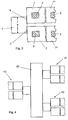
- the frequency diplexer shown in perspective in FIG. 1 consists of a rectangular waveguide 1, on the end face two waveguide filters tuned to different frequency bands 2 and 3 are coupled. These two waveguide filters 2 and 3 consist of cavity resonators, which are over apertures are coupled together.
- the coupling of the waveguide filter 2 and 3 to the face of the rectangular waveguide 1 takes place via inductive coupling plates 4 and 5, which parallel to the broad side a of the rectangular waveguide 1 side by side are arranged. Via the inductive coupling panels 4 and 5 (dotted areas in Figure 1) becomes the x component of the magnetic field in the rectangular waveguide 1 coupled.
- each filter can be designed individually (Single filter design) and then to the frequency diplexer be combined. If the filters are designed that they are within a larger frequency band (e.g. microwave radio frequency band) are tunable, so the frequency diplexer flexible to any frequency channel combination be tuned within the frequency band without a new overall design of the frequency diplexer is required.
- a larger frequency band e.g. microwave radio frequency band
- Figure 2 is the top view of the frequency diplexer described above shown. Here it is indicated that the rectangular waveguide 1 coupled filter also from several Cavity resonators 2, 21 and 3, 31 can exist.
- the coupled to the rectangular waveguide 1 Filters dielectric resonators. That is, the cavity resonators 2, 21 and 3, 31 are at least partially with a Dielectric 6, 7 and 8, 9 filled.
- FIG. 4 shows are several to the side of a collecting waveguide 10 according to the invention Frequency diplexers 11, 12 and 13 coupled. Each filter is the frequency diplexer 11, 12 and 13 tuned to another frequency channel.
Landscapes
- Control Of Motors That Do Not Use Commutators (AREA)
Applications Claiming Priority (2)
| Application Number | Priority Date | Filing Date | Title |
|---|---|---|---|
| DE1997101725 DE19701725C1 (de) | 1997-01-20 | 1997-01-20 | Frequenzdiplexer |
| DE19701725 | 1997-01-20 |
Publications (2)
| Publication Number | Publication Date |
|---|---|
| EP0854532A2 true EP0854532A2 (fr) | 1998-07-22 |
| EP0854532A3 EP0854532A3 (fr) | 1999-03-17 |
Family
ID=7817781
Family Applications (1)
| Application Number | Title | Priority Date | Filing Date |
|---|---|---|---|
| EP97120919A Ceased EP0854532A3 (fr) | 1997-01-20 | 1997-11-28 | Duplexeur de fréquence |
Country Status (2)
| Country | Link |
|---|---|
| EP (1) | EP0854532A3 (fr) |
| DE (1) | DE19701725C1 (fr) |
Cited By (2)
| Publication number | Priority date | Publication date | Assignee | Title |
|---|---|---|---|---|
| CN105048052A (zh) * | 2015-07-08 | 2015-11-11 | 广东国华新材料科技股份有限公司 | 一种可调谐的介质谐振器及介质滤波器 |
| CN110808440A (zh) * | 2019-11-12 | 2020-02-18 | 深圳市国人射频通信有限公司 | 一种介质波导双工器 |
Families Citing this family (1)
| Publication number | Priority date | Publication date | Assignee | Title |
|---|---|---|---|---|
| CN110797621B (zh) * | 2019-11-12 | 2022-03-11 | 深圳国人科技股份有限公司 | 介质波导双工器公共端口的结构 |
Family Cites Families (5)
| Publication number | Priority date | Publication date | Assignee | Title |
|---|---|---|---|---|
| BE538357A (fr) * | 1954-05-28 | |||
| NL260263A (fr) * | 1960-06-24 | |||
| DE2708306C2 (de) * | 1977-02-25 | 1982-12-23 | Siemens AG, 1000 Berlin und 8000 München | Frequenzweiche |
| JPH0680963B2 (ja) * | 1988-05-13 | 1994-10-12 | 日本電気株式会社 | マイクロ波帯分波器 |
| DE19609566C1 (de) * | 1996-03-13 | 1997-08-21 | Bosch Gmbh Robert | Frequenzdiplexer |
-
1997
- 1997-01-20 DE DE1997101725 patent/DE19701725C1/de not_active Expired - Fee Related
- 1997-11-28 EP EP97120919A patent/EP0854532A3/fr not_active Ceased
Cited By (3)
| Publication number | Priority date | Publication date | Assignee | Title |
|---|---|---|---|---|
| CN105048052A (zh) * | 2015-07-08 | 2015-11-11 | 广东国华新材料科技股份有限公司 | 一种可调谐的介质谐振器及介质滤波器 |
| CN105048052B (zh) * | 2015-07-08 | 2018-07-27 | 广东国华新材料科技股份有限公司 | 一种可调谐的介质谐振器及介质滤波器 |
| CN110808440A (zh) * | 2019-11-12 | 2020-02-18 | 深圳市国人射频通信有限公司 | 一种介质波导双工器 |
Also Published As
| Publication number | Publication date |
|---|---|
| EP0854532A3 (fr) | 1999-03-17 |
| DE19701725C1 (de) | 1998-06-18 |
Similar Documents
| Publication | Publication Date | Title |
|---|---|---|
| DE4447740B4 (de) | Akustisches Oberflächenwellenfilter | |
| DE3213436A1 (de) | Bandfilter | |
| DE1266892B (de) | Oberwellensperrfilter in Form eines Hohlleiterabschnitts mit mehreren Stichleitungen | |
| DE69125641T2 (de) | Modulares dielektrisches Bandsperrfilter | |
| EP0751579B1 (fr) | Filtre hyperfréquence | |
| DE19701725C1 (de) | Frequenzdiplexer | |
| EP0250857B1 (fr) | Filtre à micro-ondes | |
| DE3329057C2 (fr) | ||
| DE69420924T2 (de) | Bandpassfilter mit gekoppelten resonatoren | |
| DE2001433B2 (de) | Bandpaßfilter | |
| DE19623144A1 (de) | Mikrowellenfilter, bestehend aus mehreren Koaxial-Resonatoren | |
| DE1942909A1 (de) | Filter fuer sehr kurze elektromagnetische Wellen | |
| DE2640210A1 (de) | Filter fuer sehr kurze elektromagnetische wellen | |
| DE19609566C1 (de) | Frequenzdiplexer | |
| DE4116755C2 (de) | Mikrowellenfilter | |
| DE4340123C2 (de) | Hohlleitermultiplexer/ -demultiplexer | |
| DE4434642A1 (de) | Kammfilter | |
| EP0119628B1 (fr) | Emetteur à large bande pour ondes électromagnétiques courtes | |
| DE1203843B (de) | Hohlleiterbrueckenschaltung | |
| DE2738613B2 (de) | Aus konzentrierten Schaltelementen bestehende Filterschaltung für den Bereich der Meter- und Dezimeterwellen | |
| DE19818947C1 (de) | Bandpaß-Filter | |
| DE4024480A1 (de) | Frequenzweiche | |
| DE3240255C1 (de) | Kapazitiv abstimmbares Mehrkreisfilter | |
| DE19752100C1 (de) | Richtungsfilter | |
| DE3843259C1 (fr) |
Legal Events
| Date | Code | Title | Description |
|---|---|---|---|
| PUAI | Public reference made under article 153(3) epc to a published international application that has entered the european phase |
Free format text: ORIGINAL CODE: 0009012 |
|
| AK | Designated contracting states |
Kind code of ref document: A2 Designated state(s): DE FR IT SE |
|
| PUAL | Search report despatched |
Free format text: ORIGINAL CODE: 0009013 |
|
| AK | Designated contracting states |
Kind code of ref document: A3 Designated state(s): AT BE CH DE DK ES FI FR GB GR IE IT LI LU MC NL PT SE |
|
| 17P | Request for examination filed |
Effective date: 19990917 |
|
| AKX | Designation fees paid |
Free format text: DE FR IT SE |
|
| RAP1 | Party data changed (applicant data changed or rights of an application transferred) |
Owner name: MARCONI COMMUNICATIONS GMBH |
|
| 17Q | First examination report despatched |
Effective date: 20031126 |
|
| APBN | Date of receipt of notice of appeal recorded |
Free format text: ORIGINAL CODE: EPIDOSNNOA2E |
|
| APBR | Date of receipt of statement of grounds of appeal recorded |
Free format text: ORIGINAL CODE: EPIDOSNNOA3E |
|
| APAF | Appeal reference modified |
Free format text: ORIGINAL CODE: EPIDOSCREFNE |
|
| APBT | Appeal procedure closed |
Free format text: ORIGINAL CODE: EPIDOSNNOA9E |
|
| STAA | Information on the status of an ep patent application or granted ep patent |
Free format text: STATUS: THE APPLICATION HAS BEEN REFUSED |
|
| RAP1 | Party data changed (applicant data changed or rights of an application transferred) |
Owner name: ERICSSON AB |
|
| 18R | Application refused |
Effective date: 20070215 |