EP0854536A2 - Fibre reinforced plastic moulding with integrated antenna - Google Patents
Fibre reinforced plastic moulding with integrated antenna Download PDFInfo
- Publication number
- EP0854536A2 EP0854536A2 EP98100191A EP98100191A EP0854536A2 EP 0854536 A2 EP0854536 A2 EP 0854536A2 EP 98100191 A EP98100191 A EP 98100191A EP 98100191 A EP98100191 A EP 98100191A EP 0854536 A2 EP0854536 A2 EP 0854536A2
- Authority
- EP
- European Patent Office
- Prior art keywords
- fibers
- shaped part
- fabric
- part according
- wires
- Prior art date
- Legal status (The legal status is an assumption and is not a legal conclusion. Google has not performed a legal analysis and makes no representation as to the accuracy of the status listed.)
- Granted
Links
Images



Classifications
-
- H—ELECTRICITY
- H01—ELECTRIC ELEMENTS
- H01Q—ANTENNAS, i.e. RADIO AERIALS
- H01Q1/00—Details of, or arrangements associated with, antennas
- H01Q1/12—Supports; Mounting means
- H01Q1/22—Supports; Mounting means by structural association with other equipment or articles
- H01Q1/2208—Supports; Mounting means by structural association with other equipment or articles associated with components used in interrogation type services, i.e. in systems for information exchange between an interrogator/reader and a tag/transponder, e.g. in Radio Frequency Identification [RFID] systems
- H01Q1/2241—Supports; Mounting means by structural association with other equipment or articles associated with components used in interrogation type services, i.e. in systems for information exchange between an interrogator/reader and a tag/transponder, e.g. in Radio Frequency Identification [RFID] systems used in or for vehicle tyres
-
- H—ELECTRICITY
- H01—ELECTRIC ELEMENTS
- H01Q—ANTENNAS, i.e. RADIO AERIALS
- H01Q1/00—Details of, or arrangements associated with, antennas
- H01Q1/27—Adaptation for use in or on movable bodies
- H01Q1/32—Adaptation for use in or on road or rail vehicles
-
- H—ELECTRICITY
- H01—ELECTRIC ELEMENTS
- H01Q—ANTENNAS, i.e. RADIO AERIALS
- H01Q1/00—Details of, or arrangements associated with, antennas
- H01Q1/27—Adaptation for use in or on movable bodies
- H01Q1/32—Adaptation for use in or on road or rail vehicles
- H01Q1/325—Adaptation for use in or on road or rail vehicles characterised by the location of the antenna on the vehicle
- H01Q1/3266—Adaptation for use in or on road or rail vehicles characterised by the location of the antenna on the vehicle using the mirror of the vehicle
-
- H—ELECTRICITY
- H01—ELECTRIC ELEMENTS
- H01Q—ANTENNAS, i.e. RADIO AERIALS
- H01Q1/00—Details of, or arrangements associated with, antennas
- H01Q1/27—Adaptation for use in or on movable bodies
- H01Q1/32—Adaptation for use in or on road or rail vehicles
- H01Q1/325—Adaptation for use in or on road or rail vehicles characterised by the location of the antenna on the vehicle
- H01Q1/3283—Adaptation for use in or on road or rail vehicles characterised by the location of the antenna on the vehicle side-mounted antennas, e.g. bumper-mounted, door-mounted
-
- H—ELECTRICITY
- H01—ELECTRIC ELEMENTS
- H01Q—ANTENNAS, i.e. RADIO AERIALS
- H01Q1/00—Details of, or arrangements associated with, antennas
- H01Q1/36—Structural form of radiating elements, e.g. cone, spiral, umbrella; Particular materials used therewith
- H01Q1/38—Structural form of radiating elements, e.g. cone, spiral, umbrella; Particular materials used therewith formed by a conductive layer on an insulating support
-
- H—ELECTRICITY
- H01—ELECTRIC ELEMENTS
- H01Q—ANTENNAS, i.e. RADIO AERIALS
- H01Q1/00—Details of, or arrangements associated with, antennas
- H01Q1/40—Radiating elements coated with or embedded in protective material
Definitions
- the invention relates to a fiber-reinforced plastic molded part.
- a fiber-reinforced plastic mold shows z. B. EP 0 531 840 B1.
- a fiber malt provided with a binder from a resin-hardener system at a temperature at which the resin-hardener system behaves thermoplastic, preformed and then cured thermoset to the preform.
- SMC molding compound UP resin, glass fiber reinforced
- antennas here are generally transmitting and / or receiving antennas such.
- the invention has for its object to save space with fiber-reinforced antennas To connect molded plastic parts.
- this object is achieved in that the fiber-reinforced Plastic molding at least one antenna is integrated. This creates new designs possible e.g. B. in portable radio, television or cell phones.
- the fibers are used to reinforce the molded part be used, an electrical conductivity.
- the antenna is made of these fibers or the antennas are formed.
- Carbon fibers have proven to be particularly useful since they are both have electrical conductivity as well as good tensile strength.
- the molded part made of up to 60 percent by weight carbon fibers.
- metal fibers preferably copper fibers (wires).
- a fabric is pressed into the molded part, which in the warp or weft direction carbon fibers and / or metal fibers (wires), preferred Has copper fibers (wires).
- the tissue is pressed in e.g. B. after processes specified in EP 0 531 840 B1.
- the thickness and / or length of the fibers is selected depending on the required antenna tuning.
- Conveniently are the carbon fibers and / or metal fibers (wires) in the fabric Spaced from each other. A distance of 5 mm has been found in tests proven advantageous. After contacting, there were good reception qualities in the Radio.
- the fibers or the fabric are cured UP or vinyl ester resin coated. This can prevent any damage or displacement the fiber strands take place during further processing into the SMC molded part.
- the molded parts described can be particularly advantageous with the integrated Arrange the antenna or antennas on a vehicle, e.g. B. in the trunk lid or in or on the bumper.
- This Metal shielding is advantageously a synthetic vapor-coated with aluminum Fiber fabric or fleece.
- the insertion of the antenna into the molded part can be done by weaving in as described the electrically conductive fibers or wires in the warp or weft direction in the Tissue. But it can also be sewn on (e.g. zigzag stitch) or Glue on the fabric.
- FIG. 1 shows a top view of a carbon fiber laminate which forms a molded part 4.
- the individual carbon fibers 1 are arranged in parallel at a distance of approximately 5 mm. If these carbon fibers 1 are contacted, an antenna can be formed from them.
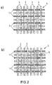
- FIG. 2a shows a fabric made of carbon fibers 1 with glass fibers 2.
- the carbon fibers 1 are each arranged adjacent to a glass fiber 2 and vice versa, the fibers are arranged parallel and at a distance from each other.
- Fig. 2b shows a fabric like Fig. 2a only the fabric is additionally pretreated here, so that the crossing points 5 are fixed. A fixed crossing point 5 is highlighted as an example in FIG. 2b.
- This fabric is coated with hardened UP or vinyl ester resin. The dimensional stability is hereby achieved.
- FIG. 3a shows a fabric 4 with carbon fibers 1.
- the fabric here is as in FIG. 2b pre-treated.
- 3b shows this fabric deformed and hardened. This is shown in FIG. 3c
- the carbon fibers 1 in these Molded parts can then be used as antennas.
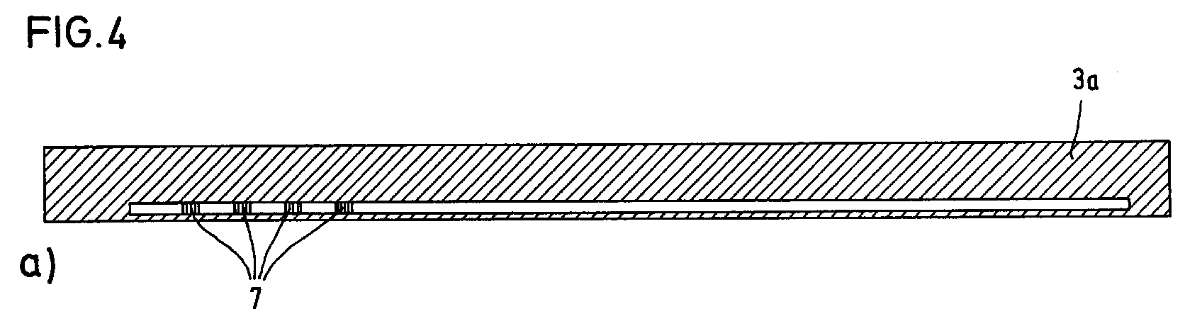
- FIG. 4a, b show pressed-in receiving antennas in the primary molded part 3a (FIG. 4a) and in the secondary molding 3b (Fig. 4b).
- the antenna is identified by reference number 7.
- 5a, b show a similar arrangement, but for transmit antennas.
- additional another metal-coated (preferably aluminum-coated) fabric 8 for Shielding provided.
- the figures only show the arrangement of Antennas 7 in one form 3.
Landscapes
- Engineering & Computer Science (AREA)
- Remote Sensing (AREA)
- Reinforced Plastic Materials (AREA)
- Details Of Aerials (AREA)
- Woven Fabrics (AREA)
- Moulding By Coating Moulds (AREA)
Abstract
Zur platzsparenden Anordnung von Sende- und Empfangsantennen wird vorgeschlagen,
die Antennen (7) in faserverstärkte Kunststoff-Formteile (3) zu integrieren.
Description
Die Erfindung betrifft ein faserverstärktes Kunststoff-Formteil.The invention relates to a fiber-reinforced plastic molded part.
Ein faserverstärktes Kunststoff-Formte zeigt z. B. EP 0 531 840 B1. Hier wird zunächst eine mit einem Bindemittel aus einem Harz-Härter-System versehene Fasermalte bei einer Temperatur, bei der sich das Harz-Härter-System thermoplastisch verhält, vorgeformt und anschließend duroplastisch zum Vorformling ausgehärtet. Anschließend wird SMC-Formmasse (UP-Harz, glasfaserverstärkt) auf den derart hergestellten Vorformling aufgegeben und mit diesem zum Formte verpreßt.A fiber-reinforced plastic mold shows z. B. EP 0 531 840 B1. Here is first a fiber malt provided with a binder from a resin-hardener system at a temperature at which the resin-hardener system behaves thermoplastic, preformed and then cured thermoset to the preform. Subsequently is SMC molding compound (UP resin, glass fiber reinforced) on the so produced Preform given and pressed with this to form.
Je nach Kundenanforderung müssen bis zu sechs Antennen je Fahrzeug untergebracht werden. Der Fahrzeugkonstrukteur steht vor der Aufgabe, den Platz für diese Antennen am Fahrzeug zu finden.Depending on customer requirements, up to six antennas must be accommodated per vehicle will. The vehicle designer is faced with the task of making room for this Find antennas on the vehicle.
Mit Antennen sind hier allgemein Sende- und/oder Empfangsantennen z. B. für Radiogeräte, Funkgeräte, Funktelefone etc. gemeint.With antennas here are generally transmitting and / or receiving antennas such. B. for radios, Radios, radio telephones etc. meant.
Der Erfindung liegt die Aufgabe zugrunde, Antennen platzsparend mit faserverstärkten Kunststoff-Formteilen zu verbinden.The invention has for its object to save space with fiber-reinforced antennas To connect molded plastic parts.
Erfindungsgemäß wird diese Aufgabe dadurch gelöst, daß in das faserverstärkte Kunststoff-Formteil mindestens eine Antenne integriert ist. Hierdurch sind neue Designs möglich z. B. bei tragbaren Rundfunk-, Fernsehgeräten oder Handys.According to the invention, this object is achieved in that the fiber-reinforced Plastic molding at least one antenna is integrated. This creates new designs possible e.g. B. in portable radio, television or cell phones.
In bevorzugter Ausführungsform besitzen die Fasern, die zur Verstärkung des Formteils eingesetst werden, eine elektrische Leitfähigkeit. Aus diesen Fasern ist die Antenne bzw. sind die Antennen gebildet.In a preferred embodiment, the fibers are used to reinforce the molded part be used, an electrical conductivity. The antenna is made of these fibers or the antennas are formed.
Kohlefasern haben sich als besonders zweckmäßig erwiesen, da sie sowohl eine elektrische Leitfähigkeit als auch eine gute Zugfestigkeit besitzen. Bevorzugt besteht das Formteil aus bis zu 60 Gewichtsprozent Kohlefasern. Ebenfalls von Vorteil sind auch Metallfasern (Drähte), bevorzugt Kupferfasern (Drähte).Carbon fibers have proven to be particularly useful since they are both have electrical conductivity as well as good tensile strength. Preferably there is the molded part made of up to 60 percent by weight carbon fibers. Are also beneficial also metal fibers (wires), preferably copper fibers (wires).
In bevorzugter Ausführungsform wird ein Gewebe in das Formteil eingepreßt, welches in Kette- oder Schußrichtung Kohlefasern und/oder Metallfasern (Drähte), bevorzugt Kupferfasern (Drähte), aufweist. Das Einpressen des Gewebes erfolgt z. B. nach dem in der EP 0 531 840 B1 angegebenen Verfahren. Die Dicke und/oder Länge der Fasern ist dabei je nach der erforderlichen Antennenabstimmung ausgesucht. Zweckmäßigerweise sind die Kohlefasern und/oder Metallfasern (Drähte) im Gewebe mit Abstand voneinander angeordnet. Ein Abstand von 5 mm hat sich in Versuchen als vorteilhaft erwiesen. Nach der Kontaktierung zeigten sich gute Empfangsqualitäten im Rundfunkgerät.In a preferred embodiment, a fabric is pressed into the molded part, which in the warp or weft direction carbon fibers and / or metal fibers (wires), preferred Has copper fibers (wires). The tissue is pressed in e.g. B. after processes specified in EP 0 531 840 B1. The thickness and / or length of the fibers is selected depending on the required antenna tuning. Conveniently are the carbon fibers and / or metal fibers (wires) in the fabric Spaced from each other. A distance of 5 mm has been found in tests proven advantageous. After contacting, there were good reception qualities in the Radio.
In besonderer Ausführungsform sind die Fasern bzw. das Gewebe mit ausgehärtetem UP- oder Vinylesterharz beschichtet. Hierdurch kann keine Beschädigung oder Verschiebung der Faserstränge bei der Weiterverarbeitung zum SMC-Formteil erfolgen.In a special embodiment, the fibers or the fabric are cured UP or vinyl ester resin coated. This can prevent any damage or displacement the fiber strands take place during further processing into the SMC molded part.
Besonders vorteilhaft lassen sich die beschriebenen Formteile mit der integrierten Antenne bzw. den Antennen an einem Fahrzeug anordnen, z. B. im Kofferraumdeckel oder im oder am Stoßfänger.The molded parts described can be particularly advantageous with the integrated Arrange the antenna or antennas on a vehicle, e.g. B. in the trunk lid or in or on the bumper.
Bei Sendeantennen wird bevorzugt zum Schutz z. B. der Fahrzeuginsassen in Kraftfahrzeugen noch eine zusätzliche Metallabschirmung in das Formteil integriert. Diese Metallabschirmung ist vorteilhafterweise ein mit Aluminium bedampftes synthetisches Fasergewebe oder Vlies.In the case of transmitting antennas, z. B. the vehicle occupants in motor vehicles an additional metal shield is integrated in the molded part. This Metal shielding is advantageously a synthetic vapor-coated with aluminum Fiber fabric or fleece.
Das Einbringen der Antenne in das Formteil kann wie beschrieben durch das Einweben der elektrisch leitfähigen Fasern oder Drähte in Kette- oder Schußrichtung in das Gewebe erfolgen. Es kann aber auch durch Aufnähen (z. B. Zick-Zack-Stich) oder Aufkleben auf das Gewebe erfolgen. The insertion of the antenna into the molded part can be done by weaving in as described the electrically conductive fibers or wires in the warp or weft direction in the Tissue. But it can also be sewn on (e.g. zigzag stitch) or Glue on the fabric.
Weitere Merkmale der Erfindung ergeben sich aus den Figuren, die nachfolgend beschrieben sind. Es zeigt:
- Fig. 1
- ein Kohlefaserlaminat,
- Fig. 2a
- eine Draufsicht auf ein Gewebe mit Kohlefaserrovings,
- Fig. 2b
- eine Draufsicht auf ein vorbehandeltes Gewebe mit Kohlefaserrovings,
- Fig. 3a
- ein Gewebe mit Kohlefaserrovings ähnlich Fig. 2b,
- Fig. 3b
- das Gewebe von Fig. 3a verformt und gehärtet und
- Fig. 3c
- das Gewebe von Fig. 3b mit SMC verpreßt,
- Fig. 4
- eingepreßte Empfangsantennen im Primärformteil (Fig. 4a) und im Sekundärformteil (Fig. 4b), und
- Fig. 5
- eingepreßte Sendeantennen im Primärformteil (Fig. 5a) und im Sekundärformteil (Fig. 5b).
- Fig. 1
- a carbon fiber laminate,
- Fig. 2a
- a plan view of a fabric with carbon fiber rovings,
- Fig. 2b
- a plan view of a pretreated fabric with carbon fiber rovings,
- Fig. 3a
- a fabric with carbon fiber rovings similar to FIG. 2b,
- Fig. 3b
- the fabric of Fig. 3a deformed and hardened and
- Fig. 3c
- 3b pressed with SMC,
- Fig. 4
- pressed-in receiving antennas in the primary molding (FIG. 4a) and in the secondary molding (FIG. 4b), and
- Fig. 5
- pressed-in transmitter antennas in the primary molding (FIG. 5a) and in the secondary molding (FIG. 5b).
Fig. 1 zeigt eine Draufsicht auf ein Kohlefaserlaminat, welches ein Formteil 4 bildet.
Die einzelnen Kohlefasern 1 sind parallel in einem Abstand von ca. 5 mm angeordnet.
Werden diese Kohlefasern 1 kontaktiert, kann aus ihnen eine Antenne gebildet werden.1 shows a top view of a carbon fiber laminate which forms a molded
Fig. 2a zeigt ein Gewebe aus Kohlefasern 1 mit Glasfasern 2. Die Kohlefasern 1 sind
jeweils einer Glasfaser 2 benachbart angeordnet und umgekehrt, wobei die Fasern
parallel und mit Abstand voneinander angeordnet sind. Fig. 2b zeigt ein Gewebe wie
Fig. 2a nur ist das Gewebe hier zusätzlich vorbehandelt, so daß die Kreuzungspunkte
5 fixiert sind. In der Fig. 2b ist beispielhaft ein fixierter Kreuzungspunkt 5 hervorgehoben.
Dieses Gewebe ist mit ausgehärtetem UP- oder Vinylesterharz beschichtet.
Hierdurch ist die Formstabilität erreicht.2a shows a fabric made of
Fig. 3a zeigt ein Gewebe 4 mit Kohlefasern 1. Das Gewebe ist hierbei wie in Fig. 2b
vorbehandelt. Fig. 3b zeigt dieses Gewebe verformt und gehärtet. In Fig. 3c wird diese
Gewebe 4 mit SMC 6 zu einem Formteil 3 verpreßt. Die Kohlefasern 1 in diesen
Formteilen lassen sich dann als Antennen verwenden.FIG. 3a shows a
Fig. 4a, b zeigen eingepreßte Empfangsantennen im Primärformteil 3a (Fig. 4a) und
im Sekundärformteil 3b (Fig. 4b). Die Antenne ist mit dem Bezugszeichen 7 gekennzeichnet.4a, b show pressed-in receiving antennas in the primary molded
Fig. 5a, b zeigen eine ähnliche Anordnung, jedoch für Sendeantennen. Hier ist zusätzlich
noch ein metallbedampftes (bevorzugt aluminiumbedampftes) Gewebe 8 zur
Abschirmung vorgesehen. Die Figuren zeigen nur schematisch die Anordnung von
Antennen 7 in einem Formte 3.5a, b show a similar arrangement, but for transmit antennas. Here is additional
another metal-coated (preferably aluminum-coated)
Claims (11)
Applications Claiming Priority (4)
| Application Number | Priority Date | Filing Date | Title |
|---|---|---|---|
| DE19701147 | 1997-01-15 | ||
| DE19701147 | 1997-01-15 | ||
| DE1997129972 DE19729972A1 (en) | 1997-07-12 | 1997-07-12 | Plastics moulding for e.g. mobile telephone |
| DE19729972 | 1997-07-12 |
Publications (3)
| Publication Number | Publication Date |
|---|---|
| EP0854536A2 true EP0854536A2 (en) | 1998-07-22 |
| EP0854536A3 EP0854536A3 (en) | 2000-07-05 |
| EP0854536B1 EP0854536B1 (en) | 2007-05-09 |
Family
ID=26033111
Family Applications (1)
| Application Number | Title | Priority Date | Filing Date |
|---|---|---|---|
| EP98100191A Expired - Lifetime EP0854536B1 (en) | 1997-01-15 | 1998-01-08 | Fibre reinforced plastic moulding with integrated antenna |
Country Status (3)
| Country | Link |
|---|---|
| EP (1) | EP0854536B1 (en) |
| AT (1) | ATE362202T1 (en) |
| DE (1) | DE59813996D1 (en) |
Cited By (17)
| Publication number | Priority date | Publication date | Assignee | Title |
|---|---|---|---|---|
| EP1221738A3 (en) * | 2000-12-27 | 2002-10-23 | The Furukawa Electric Co., Ltd. | Small antenna and manufacturing method thereof |
| EP1241731A3 (en) * | 2001-03-16 | 2003-09-17 | DaimlerChrysler AG | Antenna arrangement |
| WO2004034511A3 (en) * | 2002-09-12 | 2004-06-17 | Daimler Chrysler Ag | Integrated antenna structures, integrated electronic component structures and method for the production thereof |
| US6950068B2 (en) | 2001-11-15 | 2005-09-27 | Filtronic Lk Oy | Method of manufacturing an internal antenna, and antenna element |
| US6970423B2 (en) | 2001-01-18 | 2005-11-29 | Lucent Technologies Inc. | Universal mobile telecommunications system (UMTS) quality of service (QoS) supporting asymmetric traffic classes |
| FR2884471A1 (en) * | 2005-04-18 | 2006-10-20 | Plastic Omnium Cie | REINFORCING PART FOR A MOTOR VEHICLE AND USE OF SUCH A PART AS ANTENNA |
| EP1783859A1 (en) * | 2005-10-20 | 2007-05-09 | EADS Deutschland GmbH | Manufacturing method for a structure-integrated antenna |
| WO2008012300A1 (en) * | 2006-07-26 | 2008-01-31 | Universität Bremen | Antenna in a fibre-reinforced composite material and method for formation of an antenna using a fibre-reinforced composite material |
| WO2008019157A1 (en) * | 2006-08-08 | 2008-02-14 | Sensormatic Electronics Corporation | Thin-film eas and rfid antennas |
| GB2444360A (en) * | 2006-11-30 | 2008-06-04 | Cotech Inc | Antenna embedded in a laminated and moulded shell of a device |
| DE102006056890A1 (en) * | 2006-12-01 | 2008-06-05 | Airbus Deutschland Gmbh | Wall element for e.g. cockpit, of aircraft, has integrated antenna device designed such that high frequency radiation is emitted towards radiation area, where radiation is absorbed towards absorbing area |
| US8164527B2 (en) | 2011-03-03 | 2012-04-24 | Tangitek, Llc | Antenna apparatus and method for reducing background noise and increasing reception sensitivity |
| US8854275B2 (en) | 2011-03-03 | 2014-10-07 | Tangitek, Llc | Antenna apparatus and method for reducing background noise and increasing reception sensitivity |
| US9055667B2 (en) | 2011-06-29 | 2015-06-09 | Tangitek, Llc | Noise dampening energy efficient tape and gasket material |
| US10262775B2 (en) | 2011-07-11 | 2019-04-16 | Tangitek, Llc | Energy efficient noise dampening cables |
| CN114447581A (en) * | 2020-11-06 | 2022-05-06 | 大众汽车股份公司 | Antenna device |
| US11426950B2 (en) | 2015-07-21 | 2022-08-30 | Tangitek, Llc | Electromagnetic energy absorbing three dimensional flocked carbon fiber composite materials |
Family Cites Families (6)
| Publication number | Priority date | Publication date | Assignee | Title |
|---|---|---|---|---|
| US4370658A (en) * | 1981-04-29 | 1983-01-25 | Hill Fred G | Antenna apparatus and method for making same |
| DE3248147A1 (en) * | 1982-12-27 | 1984-06-28 | Siemens AG, 1000 Berlin und 8000 München | METALIZED PLASTIC MOLDED PARTS FOR TECHNICAL HOUSING FOR SHIELDING AGAINST ELECTROMAGNETIC INTERFERENCE |
| JPS6146099A (en) * | 1984-08-10 | 1986-03-06 | 株式会社ブリヂストン | Electromagnetic wave reflector |
| JPS62216300A (en) * | 1986-03-17 | 1987-09-22 | 株式会社イナックス | Manufacture of conductive nonwoven fabric composite molded board |
| DE4008899C1 (en) * | 1990-03-20 | 1991-04-18 | Webasto Ag Fahrzeugtechnik, 8035 Stockdorf, De | Spoiler arrangement for roof of vehicle - comprises frame of glass-fibre reinforced polyester resin, lateral member and angled front spoiler section |
| DE4116232A1 (en) * | 1991-05-17 | 1992-11-19 | Hirschmann Richard Gmbh Co | ANTENNA ARRANGEMENT |
-
1998
- 1998-01-08 EP EP98100191A patent/EP0854536B1/en not_active Expired - Lifetime
- 1998-01-08 DE DE59813996T patent/DE59813996D1/en not_active Expired - Fee Related
- 1998-01-08 AT AT98100191T patent/ATE362202T1/en not_active IP Right Cessation
Cited By (23)
| Publication number | Priority date | Publication date | Assignee | Title |
|---|---|---|---|---|
| EP1221738A3 (en) * | 2000-12-27 | 2002-10-23 | The Furukawa Electric Co., Ltd. | Small antenna and manufacturing method thereof |
| US6639557B2 (en) | 2000-12-27 | 2003-10-28 | The Furukawa Electric Co., Ltd. | Small antenna and manufacturing method thereof |
| US6970423B2 (en) | 2001-01-18 | 2005-11-29 | Lucent Technologies Inc. | Universal mobile telecommunications system (UMTS) quality of service (QoS) supporting asymmetric traffic classes |
| EP1241731A3 (en) * | 2001-03-16 | 2003-09-17 | DaimlerChrysler AG | Antenna arrangement |
| US6950068B2 (en) | 2001-11-15 | 2005-09-27 | Filtronic Lk Oy | Method of manufacturing an internal antenna, and antenna element |
| WO2004034511A3 (en) * | 2002-09-12 | 2004-06-17 | Daimler Chrysler Ag | Integrated antenna structures, integrated electronic component structures and method for the production thereof |
| FR2884471A1 (en) * | 2005-04-18 | 2006-10-20 | Plastic Omnium Cie | REINFORCING PART FOR A MOTOR VEHICLE AND USE OF SUCH A PART AS ANTENNA |
| EP1714835A1 (en) | 2005-04-18 | 2006-10-25 | Compagnie Plastic Omnium | Reinforcement part for an automotive vehicle and utilisation of such a part as an aerial |
| EP1783859A1 (en) * | 2005-10-20 | 2007-05-09 | EADS Deutschland GmbH | Manufacturing method for a structure-integrated antenna |
| WO2008012300A1 (en) * | 2006-07-26 | 2008-01-31 | Universität Bremen | Antenna in a fibre-reinforced composite material and method for formation of an antenna using a fibre-reinforced composite material |
| WO2008019157A1 (en) * | 2006-08-08 | 2008-02-14 | Sensormatic Electronics Corporation | Thin-film eas and rfid antennas |
| US7973729B2 (en) | 2006-08-08 | 2011-07-05 | Sensormatic Electronics, LLC | Thin-film EAS and RFID antennas |
| GB2444360A (en) * | 2006-11-30 | 2008-06-04 | Cotech Inc | Antenna embedded in a laminated and moulded shell of a device |
| DE102006056890A1 (en) * | 2006-12-01 | 2008-06-05 | Airbus Deutschland Gmbh | Wall element for e.g. cockpit, of aircraft, has integrated antenna device designed such that high frequency radiation is emitted towards radiation area, where radiation is absorbed towards absorbing area |
| US7701403B2 (en) | 2006-12-01 | 2010-04-20 | Airbus Deutschland Gmbh | Wall element with an antenna device |
| DE102006056890B4 (en) * | 2006-12-01 | 2011-08-25 | Airbus Operations GmbH, 21129 | Wall element with an antenna device |
| US8164527B2 (en) | 2011-03-03 | 2012-04-24 | Tangitek, Llc | Antenna apparatus and method for reducing background noise and increasing reception sensitivity |
| US8854275B2 (en) | 2011-03-03 | 2014-10-07 | Tangitek, Llc | Antenna apparatus and method for reducing background noise and increasing reception sensitivity |
| US9782948B2 (en) | 2011-03-03 | 2017-10-10 | Tangitek, Llc | Antenna apparatus and method for reducing background noise and increasing reception sensitivity |
| US9055667B2 (en) | 2011-06-29 | 2015-06-09 | Tangitek, Llc | Noise dampening energy efficient tape and gasket material |
| US10262775B2 (en) | 2011-07-11 | 2019-04-16 | Tangitek, Llc | Energy efficient noise dampening cables |
| US11426950B2 (en) | 2015-07-21 | 2022-08-30 | Tangitek, Llc | Electromagnetic energy absorbing three dimensional flocked carbon fiber composite materials |
| CN114447581A (en) * | 2020-11-06 | 2022-05-06 | 大众汽车股份公司 | Antenna device |
Also Published As
| Publication number | Publication date |
|---|---|
| EP0854536A3 (en) | 2000-07-05 |
| EP0854536B1 (en) | 2007-05-09 |
| DE59813996D1 (en) | 2007-06-21 |
| ATE362202T1 (en) | 2007-06-15 |
Similar Documents
| Publication | Publication Date | Title |
|---|---|---|
| EP0854536A2 (en) | Fibre reinforced plastic moulding with integrated antenna | |
| DE102013222435B4 (en) | Magnetic core element, magnetic core module and an inductive component using the magnetic core module | |
| DE102013112413A1 (en) | Housing part for battery housing of traction battery of electric car, has planar element for shielding surrounding area and battery against radiation, where planar element and another planar element are made of soft magnetic material | |
| DE19931189A1 (en) | Process for the production of components with electrical conductor tracks arranged therein, and components manufactured according to them, in particular as door modules for motor vehicles | |
| DE3718676C2 (en) | ||
| EP0946355B1 (en) | Multi-layer composite body | |
| DE102020118348B4 (en) | Moulded part for a mobile terminal with transmitting and/or receiving device made of carbon fibre reinforced plastic | |
| DE19963332A1 (en) | Conducting wire carrier for use in motor vehicle has rows of snap protrusions on surface of insulating coating at same interval as through holes and each able to be brought into engagement with a through hole | |
| DE19729972A1 (en) | Plastics moulding for e.g. mobile telephone | |
| EP0955191B1 (en) | One piece door module for automotive vehicle | |
| WO1997012263A2 (en) | Transponder and transponder production method | |
| DE19712098A1 (en) | Vehicle radar sensor | |
| DE10259981A1 (en) | Chassis part for vehicles has a duroplastic sandwich shell and a thermoplastic sandwich shell | |
| DE102022000284A1 (en) | Rail system for a rail-bound vehicle | |
| EP1467431B1 (en) | Adapter for contacting an antenna structure for vehicles | |
| EP1238841A2 (en) | Sliding roof panel | |
| EP1698019B1 (en) | Vehicle windshield-integrated antenna | |
| DE19729403B4 (en) | Antenna device for an anti-theft system of a motor vehicle | |
| DE102021004993A1 (en) | System for transmission of electrical energy | |
| DE102020134562A1 (en) | Housing for accommodating an electrical energy store for a vehicle | |
| DE102020008085B4 (en) | Molded part for a mobile end device with transmitter and/or receiver device made from carbon fiber reinforced plastic | |
| DE69923001T2 (en) | Reflector of electromagnetic waves and method for its production | |
| DE102013219377A1 (en) | ANTENNA ARRANGEMENT WITH ANTENNA UNIT AND CONNECTOR UNIT | |
| DE102010043430A1 (en) | Shield for electric machine e.g. electromotor installed in vehicle, has one structural component formed from electrically conductive thermoplastic resin, and another structural component formed from thermoset plastic | |
| DE102023104318A1 (en) | Communication device |
Legal Events
| Date | Code | Title | Description |
|---|---|---|---|
| PUAI | Public reference made under article 153(3) epc to a published international application that has entered the european phase |
Free format text: ORIGINAL CODE: 0009012 |
|
| AK | Designated contracting states |
Kind code of ref document: A2 Designated state(s): AT BE CH DE DK ES FI FR GB GR IT LI NL PT SE |
|
| AX | Request for extension of the european patent |
Free format text: AL;LT;LV;MK;RO;SI |
|
| PUAL | Search report despatched |
Free format text: ORIGINAL CODE: 0009013 |
|
| AK | Designated contracting states |
Kind code of ref document: A3 Designated state(s): AT BE CH DE DK ES FI FR GB GR IE IT LI LU MC NL PT SE |
|
| AX | Request for extension of the european patent |
Free format text: AL;LT;LV;MK;RO;SI |
|
| 17P | Request for examination filed |
Effective date: 20010105 |
|
| AKX | Designation fees paid |
Free format text: AT BE CH DE DK ES FI FR GB GR IT LI NL PT SE |
|
| 17Q | First examination report despatched |
Effective date: 20050405 |
|
| GRAP | Despatch of communication of intention to grant a patent |
Free format text: ORIGINAL CODE: EPIDOSNIGR1 |
|
| GRAS | Grant fee paid |
Free format text: ORIGINAL CODE: EPIDOSNIGR3 |
|
| GRAA | (expected) grant |
Free format text: ORIGINAL CODE: 0009210 |
|
| AK | Designated contracting states |
Kind code of ref document: B1 Designated state(s): AT BE CH DE DK ES FI FR GB GR IT LI NL PT SE |
|
| PG25 | Lapsed in a contracting state [announced via postgrant information from national office to epo] |
Ref country code: FI Free format text: LAPSE BECAUSE OF FAILURE TO SUBMIT A TRANSLATION OF THE DESCRIPTION OR TO PAY THE FEE WITHIN THE PRESCRIBED TIME-LIMIT Effective date: 20070509 |
|
| REG | Reference to a national code |
Ref country code: GB Ref legal event code: FG4D Free format text: NOT ENGLISH |
|
| REG | Reference to a national code |
Ref country code: CH Ref legal event code: EP |
|
| REF | Corresponds to: |
Ref document number: 59813996 Country of ref document: DE Date of ref document: 20070621 Kind code of ref document: P |
|
| PG25 | Lapsed in a contracting state [announced via postgrant information from national office to epo] |
Ref country code: SE Free format text: LAPSE BECAUSE OF FAILURE TO SUBMIT A TRANSLATION OF THE DESCRIPTION OR TO PAY THE FEE WITHIN THE PRESCRIBED TIME-LIMIT Effective date: 20070809 |
|
| PG25 | Lapsed in a contracting state [announced via postgrant information from national office to epo] |
Ref country code: ES Free format text: LAPSE BECAUSE OF FAILURE TO SUBMIT A TRANSLATION OF THE DESCRIPTION OR TO PAY THE FEE WITHIN THE PRESCRIBED TIME-LIMIT Effective date: 20070820 |
|
| NLV1 | Nl: lapsed or annulled due to failure to fulfill the requirements of art. 29p and 29m of the patents act | ||
| GBV | Gb: ep patent (uk) treated as always having been void in accordance with gb section 77(7)/1977 [no translation filed] |
Effective date: 20070509 |
|
| EN | Fr: translation not filed | ||
| PG25 | Lapsed in a contracting state [announced via postgrant information from national office to epo] |
Ref country code: PT Free format text: LAPSE BECAUSE OF FAILURE TO SUBMIT A TRANSLATION OF THE DESCRIPTION OR TO PAY THE FEE WITHIN THE PRESCRIBED TIME-LIMIT Effective date: 20071009 Ref country code: NL Free format text: LAPSE BECAUSE OF FAILURE TO SUBMIT A TRANSLATION OF THE DESCRIPTION OR TO PAY THE FEE WITHIN THE PRESCRIBED TIME-LIMIT Effective date: 20070509 Ref country code: DK Free format text: LAPSE BECAUSE OF FAILURE TO SUBMIT A TRANSLATION OF THE DESCRIPTION OR TO PAY THE FEE WITHIN THE PRESCRIBED TIME-LIMIT Effective date: 20070509 |
|
| PLBE | No opposition filed within time limit |
Free format text: ORIGINAL CODE: 0009261 |
|
| STAA | Information on the status of an ep patent application or granted ep patent |
Free format text: STATUS: NO OPPOSITION FILED WITHIN TIME LIMIT |
|
| 26N | No opposition filed |
Effective date: 20080212 |
|
| PG25 | Lapsed in a contracting state [announced via postgrant information from national office to epo] |
Ref country code: IT Free format text: LAPSE BECAUSE OF FAILURE TO SUBMIT A TRANSLATION OF THE DESCRIPTION OR TO PAY THE FEE WITHIN THE PRESCRIBED TIME-LIMIT Effective date: 20070509 Ref country code: GR Free format text: LAPSE BECAUSE OF FAILURE TO SUBMIT A TRANSLATION OF THE DESCRIPTION OR TO PAY THE FEE WITHIN THE PRESCRIBED TIME-LIMIT Effective date: 20070810 Ref country code: GB Free format text: LAPSE BECAUSE OF FAILURE TO SUBMIT A TRANSLATION OF THE DESCRIPTION OR TO PAY THE FEE WITHIN THE PRESCRIBED TIME-LIMIT Effective date: 20070509 |
|
| BERE | Be: lapsed |
Owner name: MENZOLIT-FIBRON G.M.B.H. Effective date: 20080131 |
|
| PG25 | Lapsed in a contracting state [announced via postgrant information from national office to epo] |
Ref country code: FR Free format text: LAPSE BECAUSE OF FAILURE TO SUBMIT A TRANSLATION OF THE DESCRIPTION OR TO PAY THE FEE WITHIN THE PRESCRIBED TIME-LIMIT Effective date: 20080104 |
|
| REG | Reference to a national code |
Ref country code: CH Ref legal event code: PL |
|
| PG25 | Lapsed in a contracting state [announced via postgrant information from national office to epo] |
Ref country code: LI Free format text: LAPSE BECAUSE OF NON-PAYMENT OF DUE FEES Effective date: 20080131 Ref country code: DE Free format text: LAPSE BECAUSE OF NON-PAYMENT OF DUE FEES Effective date: 20080801 Ref country code: CH Free format text: LAPSE BECAUSE OF NON-PAYMENT OF DUE FEES Effective date: 20080131 |
|
| PG25 | Lapsed in a contracting state [announced via postgrant information from national office to epo] |
Ref country code: BE Free format text: LAPSE BECAUSE OF NON-PAYMENT OF DUE FEES Effective date: 20080131 |
|
| PG25 | Lapsed in a contracting state [announced via postgrant information from national office to epo] |
Ref country code: AT Free format text: LAPSE BECAUSE OF NON-PAYMENT OF DUE FEES Effective date: 20080108 |