EP0854537A2 - Système d'antenne ultra-léger et déployable à lentille de guide d'ondes - Google Patents
Système d'antenne ultra-léger et déployable à lentille de guide d'ondes Download PDFInfo
- Publication number
- EP0854537A2 EP0854537A2 EP98100307A EP98100307A EP0854537A2 EP 0854537 A2 EP0854537 A2 EP 0854537A2 EP 98100307 A EP98100307 A EP 98100307A EP 98100307 A EP98100307 A EP 98100307A EP 0854537 A2 EP0854537 A2 EP 0854537A2
- Authority
- EP
- European Patent Office
- Prior art keywords
- waveguide
- array
- antenna
- lens
- support structure
- Prior art date
- Legal status (The legal status is an assumption and is not a legal conclusion. Google has not performed a legal analysis and makes no representation as to the accuracy of the status listed.)
- Withdrawn
Links
Images



Classifications
-
- H—ELECTRICITY
- H01—ELECTRIC ELEMENTS
- H01Q—ANTENNAS, i.e. RADIO AERIALS
- H01Q1/00—Details of, or arrangements associated with, antennas
- H01Q1/08—Means for collapsing antennas or parts thereof
-
- H—ELECTRICITY
- H01—ELECTRIC ELEMENTS
- H01Q—ANTENNAS, i.e. RADIO AERIALS
- H01Q1/00—Details of, or arrangements associated with, antennas
- H01Q1/27—Adaptation for use in or on movable bodies
- H01Q1/28—Adaptation for use in or on aircraft, missiles, satellites, or balloons
- H01Q1/288—Satellite antennas
-
- H—ELECTRICITY
- H01—ELECTRIC ELEMENTS
- H01Q—ANTENNAS, i.e. RADIO AERIALS
- H01Q15/00—Devices for reflection, refraction, diffraction or polarisation of waves radiated from an antenna, e.g. quasi-optical devices
- H01Q15/02—Refracting or diffracting devices, e.g. lens, prism
- H01Q15/04—Refracting or diffracting devices, e.g. lens, prism comprising wave-guiding channel or channels bounded by effective conductive surfaces substantially perpendicular to the electric vector of the wave, e.g. parallel-plate waveguide lens
-
- H—ELECTRICITY
- H01—ELECTRIC ELEMENTS
- H01Q—ANTENNAS, i.e. RADIO AERIALS
- H01Q15/00—Devices for reflection, refraction, diffraction or polarisation of waves radiated from an antenna, e.g. quasi-optical devices
- H01Q15/02—Refracting or diffracting devices, e.g. lens, prism
- H01Q15/06—Refracting or diffracting devices, e.g. lens, prism comprising plurality of wave-guiding channels of different length
-
- H—ELECTRICITY
- H01—ELECTRIC ELEMENTS
- H01Q—ANTENNAS, i.e. RADIO AERIALS
- H01Q19/00—Combinations of primary active antenna elements and units with secondary devices, e.g. with quasi-optical devices, for giving the antenna a desired directional characteristic
- H01Q19/06—Combinations of primary active antenna elements and units with secondary devices, e.g. with quasi-optical devices, for giving the antenna a desired directional characteristic using refracting or diffracting devices, e.g. lens
- H01Q19/062—Combinations of primary active antenna elements and units with secondary devices, e.g. with quasi-optical devices, for giving the antenna a desired directional characteristic using refracting or diffracting devices, e.g. lens for focusing
Definitions
- This invention relates generally to lens antennas, and more particularly to a collapsible lightweight waveguide lens antenna system for use in focusing relatively low frequency microwave satellite signals.
- a reflector based antenna such as a goldplated wire parabolic reflector antenna of sufficient diameter
- a panel of feed elements could also be utilized in conjunction with a panel of feed elements to produce a multiple-beam array antenna having both high gain and wide area coverage.
- the antenna must be installed on the satellite in a non-symmetrical manner, thereby causing a weight imbalance that adversely affects the performance of the satellite.
- such an antenna because of the materials used in its manufacture, such as gold plated wire and aluminum, cause the antenna to be both expensive and heavy, both being undesirable characteristics.
- a lens antenna offers an alternative for the above discussed satellite communication application. Such an antenna design is capable of providing a large aperture and excellent electrical characteristics.
- conventional lens antennas are manufactured from relatively heavy materials, such as bulk ceramic or plastic dielectrics or metal waveguide, that make such antennas impractical for satellite applications where large mass is not tolerable.
- the present invention provides a commercially practical, lightweight waveguide lens antenna system for use in satellite communication applications.
- the system of the present invention is constructed of an array of tubular metalized plastic waveguide cells supported by a truss frame.
- the system is collapsible for storage during satellite launch and exhibits an extremely large aperture to mass ratio.
- the antenna system through its design, provides symmetrical balance when installed on the satellite.
- the shape parameters of the antenna are controlled by simple geometry and not complicated tension control as required in conventional parabolic reflector based antennas.
- the passive intermodulation performance is also better and more dependable than the parabolic mesh reflector antennas with similar weight characteristics.
- the system while intended for satellite based applications, also finds use in radar and other terrestrial applications.
- the present invention provides an antenna comprising a plurality of tubular waveguide segments each having a predetermined length and interconnected to form a lightweight symmetrical honeycomb array.
- the plurality of tubular waveguide segments is collapsible for storage and shipment thereof.
- the antenna also comprises a lightweight rigid frame that supports the plurality of tubular waveguide segments and that has dimensions substantially equal to those of the array when the array is expanded into operational form.
- the frame is collapsible along with the array for storage and shipment thereof.
- a first embodiment of a waveguide lens antenna system 10 is shown coupled to a conventional deployed communication satellite 12.
- the antenna system 10 provides high gain for satellite communication signals either transmitted from or received by the satellite 12 at relatively low frequencies in the L or S band (1.2 - 2.2 Gigahertz).
- the lens system 10 includes tubular waveguide lens cells, indicated generally at 14, interconnected to form a collapsible honeycomb array.
- the honeycomb array is supported by a lightweight rigid support frame 16 that, along with the array 14, is collapsible to a size and shape desirable for transport and storage of the antenna system.
- the support structure 16 is coupled to a pair of support struts 18 which in turn are affixed to the satellite 12 in a manner that correctly positions the antenna system for focusing signals onto a satellite feed panel 20 or, alternatively, for focusing signals transmitted from the satellite 12 to a remote receiving station (not shown) or another satellite (not shown).
- the cell array 14 will be discussed in detail.
- the array 14 is constructed of a plurality of cells, such as those shown at 14a, 14b in a number sufficient to give the circular array a diameter a of approximately 10 feet.
- each of the cells in the cell array 14 is hexagonal in cross-section as shown at 24 in Figure 2a with equiangular sides having uniform lengths of about three inches.
- Each hexagonal cell preferably has a length uniform with other array cells of from six inches to twelve inches, depending upon the particular application and the frequency of the signals to be focused.
- the array thereby has a focal length b of approximately 9 feet, such that the antenna F/D is about 0.9.
- the cell has an outer wall 26 formed from a lightweight material such as commercially available materials Mylar or Kapton or metal or aluminum film of, for example, 0.0005 inches in thickness.
- the inner surface of the outer wall 26 is coated with a lightweight metal such as aluminum or silver of approximately three skin depths in thickness to give the cell its waveguide properties.
- the array may be constructed in a variety of configurations, depending upon the particular satellite application. For example, for installation with a satellite, Program Name Thuraya, manufactured by Aerospatiale, the array would have a full scale diameter greater than or equal to thirty feet for focusing multiple one degree beams at 2 GHz.
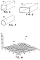
- each cell may have a square cross-section as shown at 32 in FIG. 5.
- each cell may have a rectangular cross-section with dimensions of 1" x 5" as shown at 34 in FIG. 6.
- Cells of rectangular cross-section are used in applications in which satellite signals are linearly polarized.
- each cell may have a uniform circular cross-section having a diameter of three inches, as shown at 38 in FIG. 6.
- Cells of circular or hexagonal cross-section are used in applications in which satellite signals are circularly polarized.
- the lengths of each of the cells shown in FIGS. 5-7 again will vary depending upon the particular application.
- the array contour surface may be composed of an array of cells of abruptly-varying length and/or cells arranged in a non-uniform manner.
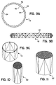
- the support structure 16 shown in FIGS. 9A-9C is circular in shape when fully deployed and, as shown in FIGS. 9A-9C, is preferably a truss frame having individual load bearing members, such as that indicated at 40, composed of graphite or some other durable lightweight material having structural integrity characteristics similar to those of graphite.
- each of the load bearing members is associated with two pivot joints 42 that maintain each load bearing member in a fully extended operational position when the antenna system is deployed, but that allow the support structure to be collapsed inwardly along with the cell array, as shown at 50 in FIG. 10, for transport and storage of the entire antenna system.
- the support structure and associated cell array may be partially collapsed, as shown at 52 in FIG. 11 for partial deployment of the antenna in response to a particular application.
- the support structure also includes fastening mechanisms 54, such as tension plates and elastic connectors, which are used to secure the array of waveguide cells to the support structure.
- the support structure may be formed from an elliptical truss frame 60.
- the Support structure may be configured as a rectangular truss frame 62.
- the support structure may be configured as a hexagonal support structure 64 formed from individual panels, such as graphite sandwich panels, and hinged in a manner that allows the support structure to be collapsed along with the waveguide cell array.
- the antenna system of the present invention may be structured in a variety of configuations and may be manufactured from a variety of lightweight materials.
- a feed horn 20 for use with the above described satellite system 10 is shown in more detail. Although more than one feed horn may be utilized with the satellite 12, it is contemplated that a single position adjustable feed horn would provide sufficient signal focusing characteristics.
- the feed horn shown has six-inch square dimensions at a first end 70.
- the horn tapers to a second end 72 having a width c of about six inches and a height d of about 2.55 inches.
- the feed horn length from the first end 70 to the second end 72 is preferably about twelve inches for use with signals having frequencies of about two gigahertz (Ghz).
- Table provides a set of exemplary structural and operational parameters for various configurations of the antenna systems described above: Array Diameter Cell Cross-Section Cell Length 12 m diameter 3" hexagonal opening 12 inches deep for Geomobile subscriber service 6 m diameter 1.5" hexagonal opening 12 inches deep for uplink 2 m diameter rectangular opening 6 inches deep for linearly polarized ground link
- FIGS. 16-19 a preferred method of manufacturing the lens waveguide cell array of the present invention will be described. While the method described below represents a preferred method of manufacturing a hexagonal cell array, it should be appreciated that arrays having waveguide cells of other configurations, such as circular or square waveguide cells, are manufactured in a similar manner.
- a aide view of multiple sheets of metalized plastic film such as those sold commercially under the tradenames Mylar and Kapton, are arranged in a stacked manner as shown at 80.
- the multiple layers of metalized plastic film 80 are discretely welded together to bond the individual sheets together as a single unit, indicated by the welded joints 82.
- the individual waveguide cells are formed or fabricated by cutting through the individual sheets with a tool shown at 84.
- the cutting process is accomplished through use of a conventional two axis laser cutting tool.
- any appropriate cutting tool capable of cutting with a high degree of accuracy may be used.
- the individual hexagonal waveguide cells are formed such that the interior walls of the waveguide cells are metal coated and each end of the cell is open. Subsequently, as shown at 86 in FIG 18, the cell array is cut so that each waveguide cell has a length according to the particular application. By forming an array as described above, the resulting array may be collapsed for storage and transport purposes, thereby minimizing the storage/cargo space required.
- the antenna system of the present invention provides numerous advantages over conventional direct radiating array antennas and reflector based antennas.
- the lightweight lattice array structure of the antenna system of the present invention promotes balanced, torsional support along the antenna cardinal axes.
- the optical properties of the antenna are controlled by simple geometry, not complicated tension control as in conventional parabolic mesh reflector antennas.
- the passive intermodulation performance exhibited by the antenna system of the present invention represents an improvement in performance and dependability over conventional parabolic mesh reflector antennas while having similar overall weight characteristics.
- the antenna system of the present invention also may be constructed to conform to a wide range of antenna F/D requirements.
- the antenna system of the present invention can also accommodate aspheric, multi-focal and other similar complex optical configurations.
- the antenna system of the present invention is primarily intended for space-borne communication applications, it is contemplated that the antenna system may also be utilized in radar, as well as other terrestrial applications, or in any application requiring a large, lightweight, stowable antenna.
Landscapes
- Physics & Mathematics (AREA)
- Engineering & Computer Science (AREA)
- Astronomy & Astrophysics (AREA)
- General Physics & Mathematics (AREA)
- Remote Sensing (AREA)
- Aviation & Aerospace Engineering (AREA)
- Aerials With Secondary Devices (AREA)
- Details Of Aerials (AREA)
- Waveguide Aerials (AREA)
Applications Claiming Priority (2)
| Application Number | Priority Date | Filing Date | Title |
|---|---|---|---|
| US783710 | 1985-10-03 | ||
| US08/783,710 US5818395A (en) | 1997-01-16 | 1997-01-16 | Ultralight collapsible and deployable waveguide lens antenna system |
Publications (2)
| Publication Number | Publication Date |
|---|---|
| EP0854537A2 true EP0854537A2 (fr) | 1998-07-22 |
| EP0854537A3 EP0854537A3 (fr) | 2000-07-12 |
Family
ID=25130169
Family Applications (1)
| Application Number | Title | Priority Date | Filing Date |
|---|---|---|---|
| EP98100307A Withdrawn EP0854537A3 (fr) | 1997-01-16 | 1998-01-09 | Système d'antenne ultra-léger et déployable à lentille de guide d'ondes |
Country Status (2)
| Country | Link |
|---|---|
| US (1) | US5818395A (fr) |
| EP (1) | EP0854537A3 (fr) |
Cited By (4)
| Publication number | Priority date | Publication date | Assignee | Title |
|---|---|---|---|---|
| FR2867617A1 (fr) * | 2004-03-10 | 2005-09-16 | Adventen | Dispositif de perturbation de la propagation d'ondes electromagnetiques, procede de fabrication et application correspondants |
| CN105811071B (zh) * | 2016-04-19 | 2018-06-15 | 吉林大学 | 圆环天线阵的支撑装置及其装配方法 |
| CN111092285A (zh) * | 2020-01-06 | 2020-05-01 | 上海航天测控通信研究所 | 一种星载可展开抛物柱面天线 |
| US11721909B2 (en) | 2021-12-20 | 2023-08-08 | Northrop Grumman Systems Corporation | Expandable hybrid reflector antenna structures and associated components and methods |
Families Citing this family (25)
| Publication number | Priority date | Publication date | Assignee | Title |
|---|---|---|---|---|
| US6618025B2 (en) | 1999-06-11 | 2003-09-09 | Harris Corporation | Lightweight, compactly deployable support structure with telescoping members |
| US6313811B1 (en) | 1999-06-11 | 2001-11-06 | Harris Corporation | Lightweight, compactly deployable support structure |
| US6239744B1 (en) | 1999-06-30 | 2001-05-29 | Radio Frequency Systems, Inc. | Remote tilt antenna system |
| SE0001674D0 (sv) * | 2000-05-05 | 2000-05-05 | Stig Petersson | Förfarande för tillverkning av invid varandra anordnade vågledarkanaler |
| US6941138B1 (en) | 2000-09-05 | 2005-09-06 | The Directv Group, Inc. | Concurrent communications between a user terminal and multiple stratospheric transponder platforms |
| FR2814614B1 (fr) * | 2000-09-25 | 2003-02-07 | Cit Alcatel | Lentille divergente a dome pour ondes hyperfrequences et antenne comportant une telle lentille |
| US6388634B1 (en) * | 2000-10-31 | 2002-05-14 | Hughes Electronics Corporation | Multi-beam antenna communication system and method |
| US20080111031A1 (en) * | 2006-11-09 | 2008-05-15 | Northrop Grumman Space & Missions Systems Corp. | Deployable flat membrane structure |
| US8384614B2 (en) | 2010-09-30 | 2013-02-26 | The United States Of America As Represented By The Administrator Of The National Aeronautics And Space Administration | Deployable wireless Fresnel lens |
| US8873168B2 (en) * | 2010-12-17 | 2014-10-28 | The Johns Hopkins University | System and method of solar flux concentration for orbital debris remediation |
| JP6391921B2 (ja) * | 2013-07-30 | 2018-09-19 | 浜松ホトニクス株式会社 | 波長板及び分割プリズム部材 |
| US10454186B2 (en) * | 2015-02-24 | 2019-10-22 | Gilat Satellite Networks Ltd. | Lightweight plastic antenna |
| JP6552326B2 (ja) * | 2015-08-07 | 2019-07-31 | 株式会社東海理化電機製作所 | 電波透過部品 |
| US10516216B2 (en) | 2018-01-12 | 2019-12-24 | Eagle Technology, Llc | Deployable reflector antenna system |
| US10707552B2 (en) | 2018-08-21 | 2020-07-07 | Eagle Technology, Llc | Folded rib truss structure for reflector antenna with zero over stretch |
| US10218076B1 (en) * | 2018-09-10 | 2019-02-26 | The Florida International University Board Of Trustees | Hexagonal waveguide based circularly polarized horn antennas |
| US10498029B1 (en) | 2019-07-15 | 2019-12-03 | Bao Tran | Cellular system |
| US10461421B1 (en) | 2019-05-07 | 2019-10-29 | Bao Tran | Cellular system |
| US11321282B2 (en) | 2019-05-17 | 2022-05-03 | Bao Tran | Blockchain cellular system |
| US10694399B1 (en) | 2019-09-02 | 2020-06-23 | Bao Tran | Cellular system |
| US10812992B1 (en) | 2019-09-02 | 2020-10-20 | Bao Tran | Cellular system |
| CN114188724B (zh) * | 2021-11-04 | 2024-11-15 | 成都频岢微电子有限公司 | 一种金属透镜及双极化金属透镜天线 |
| CN113851856B (zh) * | 2021-12-01 | 2022-02-18 | 成都频岢微电子有限公司 | 一种基于四脊波导的宽带高增益金属透镜天线 |
| CN114927854B (zh) * | 2022-06-09 | 2024-09-17 | 中国人民解放军69016部队 | 一种便携可调节角度的折叠式天线支撑装置及安装方法 |
| US12362494B2 (en) * | 2023-06-20 | 2025-07-15 | Rohde & Schwarz Gmbh & Co. Kg | Metallic waveguide antenna |
Family Cites Families (8)
| Publication number | Priority date | Publication date | Assignee | Title |
|---|---|---|---|---|
| US2599763A (en) * | 1948-12-31 | 1952-06-10 | Bell Telephone Labor Inc | Directive antenna system |
| US3329958A (en) * | 1964-06-11 | 1967-07-04 | Sylvania Electric Prod | Artificial dielectric lens structure |
| US3729743A (en) * | 1971-10-26 | 1973-04-24 | Nasa | Collapsible structure for an antenna reflector |
| US4321604A (en) * | 1977-10-17 | 1982-03-23 | Hughes Aircraft Company | Broadband group delay waveguide lens |
| US4445121A (en) * | 1981-12-18 | 1984-04-24 | General Dynamics Corporation/Convair Div. | Single membrane lens for space radar using microstrip antenna radiating elements |
| US4475323A (en) * | 1982-04-30 | 1984-10-09 | Martin Marietta Corporation | Box truss hoop |
| US5228258A (en) * | 1989-11-27 | 1993-07-20 | Fuji Jukogyo Kabushiki Kaisha | Collapsible truss structure |
| US5257034A (en) * | 1992-07-29 | 1993-10-26 | Space Systems/Loral, Inc. | Collapsible apparatus for forming a paraboloid surface |
-
1997
- 1997-01-16 US US08/783,710 patent/US5818395A/en not_active Expired - Lifetime
-
1998
- 1998-01-09 EP EP98100307A patent/EP0854537A3/fr not_active Withdrawn
Cited By (4)
| Publication number | Priority date | Publication date | Assignee | Title |
|---|---|---|---|---|
| FR2867617A1 (fr) * | 2004-03-10 | 2005-09-16 | Adventen | Dispositif de perturbation de la propagation d'ondes electromagnetiques, procede de fabrication et application correspondants |
| CN105811071B (zh) * | 2016-04-19 | 2018-06-15 | 吉林大学 | 圆环天线阵的支撑装置及其装配方法 |
| CN111092285A (zh) * | 2020-01-06 | 2020-05-01 | 上海航天测控通信研究所 | 一种星载可展开抛物柱面天线 |
| US11721909B2 (en) | 2021-12-20 | 2023-08-08 | Northrop Grumman Systems Corporation | Expandable hybrid reflector antenna structures and associated components and methods |
Also Published As
| Publication number | Publication date |
|---|---|
| EP0854537A3 (fr) | 2000-07-12 |
| US5818395A (en) | 1998-10-06 |
Similar Documents
| Publication | Publication Date | Title |
|---|---|---|
| US5818395A (en) | Ultralight collapsible and deployable waveguide lens antenna system | |
| US5557292A (en) | Multiple band folding antenna | |
| US8035573B2 (en) | Deployable panel structure for an array antenna | |
| Rao et al. | Handbook of reflector antennas and feed systems volume III: applications of reflectors | |
| CN106848558B (zh) | 航天器太阳能帆板共形天线 | |
| US5543809A (en) | Reflectarray antenna for communication satellite frequency re-use applications | |
| EP1120856A1 (fr) | Reflecteurs plats en technologie des circuits imprimes multicouches et procedes de conception associes | |
| Rusch | The current state of the reflector antenna art | |
| US11784415B2 (en) | Deployable assembly for antennas | |
| US20200411998A1 (en) | Antenna having deployable antenna fins and associated methods | |
| US20250197033A1 (en) | A Satellite Designed to be Stacked and Launched in Groups | |
| JP7724225B2 (ja) | 反射鏡アンテナの主ビームの方向を変更するためのプリズム | |
| Liu et al. | Dual-band folded-end dipole antenna for plastic CubeSats | |
| US11362427B2 (en) | Deployable horn antenna and associated methods | |
| KR102872575B1 (ko) | 저고도 각도에서 위성과 통신하기 위한 스캔 손실 감소 안테나 시스템 | |
| US6476761B2 (en) | Domed divergent lens for microwaves and an antenna incorporating it | |
| US20220294112A1 (en) | Unit cell for a reconfigurable antenna | |
| Roederer | Historical overview of the development of space antennas | |
| US7151509B2 (en) | Apparatus for use in providing wireless communication and method for use and deployment of such apparatus | |
| US20220328958A1 (en) | Corrugated ground plane apparatus for an antenna | |
| Abulgasem | High Gain Antennas for Communication between CubeSat and Ground Station | |
| Chattopadhyay et al. | Terahertz antenna technologies for space science applications | |
| US20250316898A1 (en) | Dielectric dome lenses for phased arrays | |
| Itanami et al. | Fan rib type deployable mesh antenna for satellite use | |
| Yim et al. | Design of a Wrapped Rib Mesh Reflector Antenna With a Precise Parabolic Surface and High Volume-Reduction Efficiency Using a Lightweight and Simple Mechanical Configuration |
Legal Events
| Date | Code | Title | Description |
|---|---|---|---|
| PUAI | Public reference made under article 153(3) epc to a published international application that has entered the european phase |
Free format text: ORIGINAL CODE: 0009012 |
|
| AK | Designated contracting states |
Kind code of ref document: A2 Designated state(s): DE FR GB |
|
| AX | Request for extension of the european patent |
Free format text: AL;LT;LV;MK;RO;SI |
|
| PUAL | Search report despatched |
Free format text: ORIGINAL CODE: 0009013 |
|
| AK | Designated contracting states |
Kind code of ref document: A3 Designated state(s): AT BE CH DE DK ES FI FR GB GR IE IT LI LU MC NL PT SE |
|
| AX | Request for extension of the european patent |
Free format text: AL;LT;LV;MK;RO;SI |
|
| 17P | Request for examination filed |
Effective date: 20000829 |
|
| AKX | Designation fees paid |
Free format text: DE FR GB |
|
| RAP1 | Party data changed (applicant data changed or rights of an application transferred) |
Owner name: NORTHROP GRUMMAN CORPORATION |
|
| RAP1 | Party data changed (applicant data changed or rights of an application transferred) |
Owner name: NORTHROP GRUMMAN CORPORATION |
|
| STAA | Information on the status of an ep patent application or granted ep patent |
Free format text: STATUS: THE APPLICATION HAS BEEN WITHDRAWN |
|
| 17Q | First examination report despatched |
Effective date: 20050624 |
|
| 18W | Application withdrawn |
Effective date: 20050714 |