EP0854546B1 - Doppelverriegelung eines Verbinders - Google Patents
Doppelverriegelung eines Verbinders Download PDFInfo
- Publication number
- EP0854546B1 EP0854546B1 EP97121257A EP97121257A EP0854546B1 EP 0854546 B1 EP0854546 B1 EP 0854546B1 EP 97121257 A EP97121257 A EP 97121257A EP 97121257 A EP97121257 A EP 97121257A EP 0854546 B1 EP0854546 B1 EP 0854546B1
- Authority
- EP
- European Patent Office
- Prior art keywords
- double lock
- lock member
- guide grooves
- female connector
- connector
- Prior art date
- Legal status (The legal status is an assumption and is not a legal conclusion. Google has not performed a legal analysis and makes no representation as to the accuracy of the status listed.)
- Expired - Lifetime
Links
Images


Classifications
-
- H—ELECTRICITY
- H01—ELECTRIC ELEMENTS
- H01R—ELECTRICALLY-CONDUCTIVE CONNECTIONS; STRUCTURAL ASSOCIATIONS OF A PLURALITY OF MUTUALLY-INSULATED ELECTRICAL CONNECTING ELEMENTS; COUPLING DEVICES; CURRENT COLLECTORS
- H01R13/00—Details of coupling devices of the kinds covered by groups H01R12/70 or H01R24/00 - H01R33/00
- H01R13/62—Means for facilitating engagement or disengagement of coupling parts or for holding them in engagement
- H01R13/639—Additional means for holding or locking coupling parts together, after engagement, e.g. separate keylock, retainer strap
Definitions
- This invention relates to a double lock for connectors that is designed to hold engagement between a male connector and a female connector.
- a conventional double lock for connectors includes a double lock member which is temporarily retained with a connector housing, and is regularly retained with the connector housing so as to hold an engagement between the connectors.
- EP-A-0 449 239 discloses a lock verification slider which can be advanced forwardly when a male connector housing is completely connected with a mating female connector housing.
- the male connector housing includes a pair of guide ribs which extend along an engaging direction of the lock verification slider.
- a pair of guide grooves are disposed on the lock verification slider so as to extend along an engaging direction of the lock verification slider with the male connector housing.
- the lock verification slider is in one position temporarily retained and in a second position regularly retained where the male and female connector housings are held in engagement one to another by the lock verification slider.
- the object of the invention is to provide a double lock for connectors that can reliably prevent a double lock member from playing, etc., and ensure satisfactory operability during the double lock member assembling operation. According to the double lock of the invention, it is possible to prevent noise or the like from being made after double-locked connectors that have been assembled to a motor vehicle, and further, it is possible to achieve a cost reduction.
- the guide grooves enclose substantially all the outer surfaces of the guide ribs.
- projections be disposed on the predetermined portions of the guide grooves, respectively.
- the double lock member is temporarily retained with the female connector while engaged with the female connector in a predetermined direction, and regularly retained with the female connector in the condition such that the male connector is engaged with the female connector, so that the double lock member holds the engagement of the male connector and the female connector.
- the pair of guide grooves disposed on the double lock member allow the pair of guide ribs disposed on the female connector to be inserted thereinto, respectively. Accordingly, the guide grooves guide the double lock member in such a manner that the double lock member can take a predetermined position with respect to the female connector.
- the guide grooves enclose substantially all the outer surfaces of the guide ribs.
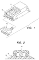
- a double lock for connectors as shown in Figs. 1 to 4 includes a double lock member 52 holding engagement between a male connector 50 and a female connector 51.
- the double lock member 52 is temporarily retained with a female connector housing 53 of the female connector 51 while engaged with the female connector housing 53 in a predetermined direction.
- the double lock member 52 is regularly retained with the female connector housing 53 in a condition such that the male connector 50 is engaged with the female connector 51, so that the double lock member 52 holds the engagement between the male connector 50 and the female connector 51.
- the aforementioned double lock for connectors may have the following three possibilities because the double lock member 52 may be subjected to a large play or the like within dimensional tolerance or the like particularly when the area of contact between the double lock member 52 and the female connector housing 53 is small.
- a double lock member 30 is engaged with a female connector housing 11 in a predetermined direction (in the direction indicated by the arrow B in Fig. 5) while allowing guide ribs 14 of a female connector 10 to be inserted into guide grooves 33 thereof.
- the double lock member 30 is temporarily retained with the female connector housing 11 as shown in Fig. 8 while engaged with the female connector housing 11 in a predetermined direction. Furthermore, the double lock member 30 is regularly retained with the female connector housing 11 as shown in Fig. 10 under a condition shown in Fig. 9 in which a male connector 20 is engaged with the female connector 10. Accordingly, it is possible for the double lock member 30 to reliably hold the engagement between the male connector 20 and the female connector 10.
- the double lock member 30 is temporarily retained with the female connector housing 11 while the double lock member 30 is engaged with the female connector housing 11 from the left side as viewed in Fig. 8 so that a retaining catch 32 disposed at the base end portion of a lock arm 31 is retained by a projection 12 disposed on the female connector housing 11. Then, when the male connector 20 is engaged with the female connector 10 from the right side as viewed in Fig.
- a retaining projection 22 disposed on a male connector housing (not shown) of the male connector 20 is retained by a fitting projection 13 disposed on the female connector housing 11 so as to ride over the fitting projection 13 while flexing the fitting projection 13 downwardly, and further, the front end of the lock arm 31 of the double lock member 30 is pressed downwardly by the retaining projection 22. Further, the double lock member 30 is retained while causing the front end portion of the lock arm 31 thereof to ride over the fitting projection 13 of the female connector housing 11 in association with the pushing operation toward the right as viewed in Fig. 9. Accordingly, the double lock member 30 is regularly retained. In other words, the double lock member 30 is in a double-locked condition.
- a pair of guide ribs 14 is disposed on the female connector housing 11 so as to extend along an engaging direction B of a double lock member 30 and so as to be apart from each other by a predetermined distance C in a direction intersecting to such engaging direction B.
- a pair of guide grooves 33 is disposed on the double lock member 30 so as to extend along the direction B of engaging the double lock member with the female connector 10 and so as to be apart from each other by a predetermined distance D in a direction intersecting to the engaging direction B.
- the respective guide grooves 33 allow the corresponding guide ribs 14 to be inserted thereinto, and enclose substantially all the outer surfaces of the guide ribs 14 by the inner sidewalls 34 and the outer sidewalls 35 thereof. Accordingly, the guide grooves 33 respectively guide the double lock member 30 in such a manner that the double lock member 30 can take a predetermined position with respect to the female connector housing 11.
- the distance D between the respective guide grooves 33 and the distance C between the respective guide ribs 14 are set so that the distance C is equal to or greater than the distance D. More specifically, the distance C between the outer side surfaces of the respective guide ribs 14 is set to a value equal to or greater than the distance D between the inner surfaces of the outer sidewalls 35 of the respective guide grooves 33.
- predetermined portions 35a the lower end portions as viewed in Fig. 7 of the outer sidewalls 35 of the guide grooves 33 are fitted with the corresponding portions of the outer side surfaces (the left side surfaces as viewed in Fig. 7) of the guide ribs 14, so that predetermined biasing forces to be applied to each other are caused.
- very small gaps 36 are respectively provided between the portions excluding the predetermined portions 35a of the outer sidewalls 35 of the respective guide grooves 33 and the outer side surfaces of the respective guide ribs 14.
- the double lock member 30 is engaged with the female connector housing 11 from the left side as viewed in Fig. 8. Further, the double lock member 30 is temporarily retained with the female connector housing 11 so that the retaining catch 32 of the lock arm 31 is retained by the projection 12 of the female connector housing 11 as shown in Fig. 8. Then, as shown in Fig. 9, the male connector 20 is engaged with the female connector 10 from the right side as viewed in Fig. 9, and when the retaining projection 22 of the male connector housing (not shown) is retained with the female connector housing 11 while riding over the fitting projection 13 of the female connector housing 11 (primary lock), the front end portion of the lock arm 31 (the right end portion as viewed in Fig. 9) of the double lock member 30 pressed downwardly by the retaining projection 22.
- the double lock member 30 is retained by the female connector housing 11 with the front end portion of the lock arm 31 riding over the fitting projection 13 of the female connector housing 11 in association with the pushing operation toward the right as viewed in Fig. 9 (secondary lock). Accordingly, the double lock member 30 is regularly retained with the female connector housing 11, and reliably holds the engagement between the male connector 20 and the female connector 10.
- the respective guide grooves 33 of the double lock member 30 allow the corresponding guide ribs 14 of the female connector housing 11 to be inserted thereinto. Therefore, the respective guide grooves 33 guide the double lock member 30 in such a manner that the double lock member 30 can take a predetermined position with respect to the female connector housing 11.
- Fig. 11 is an enlarged sectional view partially showing a double lock member and a female connector housing of a double lock for connectors, which is a second embodiment according to the invention.
- projections 40 are disposed at the predetermined portions 35a of the guide grooves 33, respectively.
- the predetermined portions 35a of the guide grooves 33 is fitted with the corresponding portions of the guide ribs 14, so that predetermined biasing forces to be applied to each other are caused through the projections 40.
- the respective guide grooves 33 of the double lock member 30 allow the guide ribs 14 of the female connector housing 11 to be inserted thereinto. Accordingly, the guide grooves 33 can guide the double lock member 30 in such a manner that the double lock member 30 can take a predetermined position with respect to the female connector housing 11. Therefore, it is possible to reliably prevent the double lock member 30 from being positioned obliquely with respect to the connector housings at the time of assembling the double lock member 30 to the female connector housing 11.
- the guide grooves 33 are formed so as to enclose substantially all the outer surfaces of the guide ribs 14 with the inner sidewalls 34 and the outer sidewalls 35 thereof, respectively, and further, the distance C between the outer side surfaces of the guide ribs 14 is set to a value equal to or greater than the distance D between the inner surfaces of the outer sidewalls 35 of the guide grooves 33. Therefore, the playing, etc. of the double lock member 30 can be reliably eliminated with satisfactory operability ensured. Accordingly, a cost reduction can be implemented by curtailing the operation time, and the making of noise or the like after the double-locked connectors have been assembled to a motor vehicle can be reliably prevented.
- the projections 40 are disposed at the predetermined portions 35a of the guide grooves 33, respectively. Therefore, when the predetermined portions 35a of the guide grooves 33 allow the corresponding guide ribs 14 to be inserted thereinto, the biasing forces to be applied to each other caused between the guide grooves 33 and the guide ribs can be concentrated on the projections 40 of the guide grooves 33 and the portions of the guide ribs 14 corresponding to the projections 40. Accordingly, the fitting forces between the guide grooves 33 and the guide ribs 14 can be increased without impairing satisfactory operability. Hence, the playing, etc. of the double lock member 30 can be eliminated more reliably.
- a pair of guide grooves disposed on the double lock member allow a pair of guide ribs disposed on the female connector to be inserted thereinto, respectively, so that the guide grooves guide the double lock member so as to allow the double lock member to take a predetermined position with respect to the female connector.
- the guide grooves enclose substantially all the outer surfaces of the guide ribs at the time of allowing the corresponding guide ribs to be inserted thereinto, respectively.
- the playing, etc., of the double lock member can be prevented reliably, and satisfactory operability during the double lock member assembling operation can be ensured. Accordingly, the making of noise or the like after the double-locked connectors have been assembled can be prevented and a cost reduction can be achieved.
- a pair of guide grooves disposed on the double lock member allow a pair of guide ribs disposed on the female connector to be inserted thereinto, respectively.
- the guide grooves guide the double lock member in such a manner that the double lock member can take a predetermined position with respect to the female connector.
- the distance between the respective guide grooves and the distance between the respective guide ribs are set so that the distance between the guide ribs is equal to or greater than the distance between the guide grooves.
- the playing, etc., of the double lock member can be prevented reliably, and satisfactory operability during the double lock member assembling operation can be ensured. Accordingly, the making of noise or the like after the double-locked connectors have been assembled to a motor vehicle can be prevented, and a cost reduction can be achieved.
Landscapes
- Details Of Connecting Devices For Male And Female Coupling (AREA)
- Connector Housings Or Holding Contact Members (AREA)
Claims (7)
- Doppelverriegelung für Steckverbinder, umfassend:dadurch gekennzeichnet, dass der Abstand (D) zwischen den jeweiligen Führungsnuten (33) und der Abstand (C) zwischen den jeweiligen Führungsrippen (14) so festgelegt ist, dass der Abstand (C) zwischen den Führungsnuten (14) größer ist als der Abstand (D) zwischen den Führungsnuten (33), und wenn den jeweiligen Führungsnuten (33) ermöglicht wird, dass die entsprechenden Führungsrippen (14) dort hinein eingesetzt werden, vorbestimmte Bereiche (35a) der Führungsnuten (33) mit den entsprechenden Bereichen der jeweiligen Führungsrippen (14) angepasst werden, so dass vorbestimmte Vorbelastungskräfte, die zwischen den Führungsrippen (14) und den Führungsnuten (33) jeweils aufgebracht werden, bewirkt werden.ein Doppelverriegelungselement (30);ein Paar Führungsrippen (14), das auf einem ersten Steckverbinder (10) so angeordnet ist, dass es sich entlang einer Eingriffsrichtung (B) des Doppelverriegelungselements (30) mit dem ersten Steckverbinder (10) erstreckt und so angeordnet ist, dass es voneinander um einen vorbestimmten Abstand (C) in einer Richtung, die die Eingriffsrichtung (B) schneidet, getrennt ist; undein Paar Führungsnuten (33), das auf dem Doppelverriegelungselement (30) so angeordnet ist, dass es sich entlang einer Eingriffsrichtung (B) des Doppelverriegelungselements (30) mit dem ersten Steckverbinder (10) erstreckt und so voneinander um einen vorbestimmten Abstand (D) in einer Richtung, die die Eingriffsrichtung (B) schneidet, getrennt ist; wobeidas Doppelverriegelungselement (30) vorläufig gehalten wird, während es mit dem ersten Steckverbinder (10) in einer vorbestimmten Richtung in Eingriff ist, wobei das Doppelverriegelungselement (30) richtig an dem ersten Steckverbinder (10) in einem Zustand gehalten wird, solcherart, dass ein zweiter Steckverbinder (20) mit dem ersten Steckverbinder (10) in Eingriff befindlich ist, so dass das Doppelverriegelungselement (30) den Eingriff zwischen dem zweiten Steckverbinder (20) und dem ersten Steckverbinder (10) hält;
- Doppelverriegelung für Steckverbinder nach Anspruch 1, wobei die Führungsnuten (33) den entsprechenden Führungsrippen (14) ermöglichen, dass sie zum Zeitpunkt des Eingriffs des Doppelverriegelungselements (30) mit dem ersten Steckverbinder (10) dort hinein eingesetzt werden, so dass die Führungsnuten (33) das Doppelverriegelungselement (30) in einer solchen Weise führen, dass das Doppelverriegelungselement (30) eine vorbestimmte vorläufige Position in bezug zu dem ersten Steckverbinder (10) einnimmt.
- Doppelverriegelung für Steckverbinder nach Anspruch 1 oder 2, wobei die Führungsnuten (33) im wesentlichen die gesamten Außenflächen der Führungsrippen (14) umschließen.
- Doppelverriegelung für Steckverbinder nach einem der Ansprüche 1 bis 3, wobei Vorsprungsbereiche (40) auf den entsprechenden Bereichen (35a) der Führungsnuten (33) jeweils angeordnet sind.
- Doppelverriegelung für Steckverbinder nach einem der Ansprüche 1 bis 4, wobei die Führungsnuten (33) jeweils Innenseitenwände (34) und Außenseitenwände (35) aufweisen, wobei ein Abstand (C) zwischen den Außenflächen der jeweiligen Führungsrippen (14) auf einen Wert festgelegt ist, der gleich oder größer als ein Abstand (D) zwischen den Innenflächen der Außenseitenwände (35) der jeweiligen Führungsnuten (33) ist.
- Doppelverriegelung für Steckverbinder nach einem der Ansprüche 4 oder 5, wobei Zwischenräume (36) jeweils durch die Vorsprungsbereiche (40), den Außenflächen der Führungsrippen (14) und den Innenflächen der Außenseitenwände (35) der Führungsnuten (33) ausgebildet sind.
- Doppelverriegelung für Steckverbinder nach einem der Ansprüche 4 oder 5, wobei Zwischenräume (36) jeweils zwischen der Innenfläche der Außenseitenwände (35) der Führungsnuten (33) ausschließlich der vorbestimmten Bereiche (35a) der Außenseitenwände (35) der jeweiligen Führungsnuten (33) und der Außenflächen der jeweiligen Führungsrippen (14) vorgesehen sind.
Applications Claiming Priority (3)
| Application Number | Priority Date | Filing Date | Title |
|---|---|---|---|
| JP563297 | 1997-01-16 | ||
| JP5632/97 | 1997-01-16 | ||
| JP9005632A JPH10199622A (ja) | 1997-01-16 | 1997-01-16 | コネクタ用二重ロック |
Publications (3)
| Publication Number | Publication Date |
|---|---|
| EP0854546A2 EP0854546A2 (de) | 1998-07-22 |
| EP0854546A3 EP0854546A3 (de) | 1999-06-16 |
| EP0854546B1 true EP0854546B1 (de) | 2003-04-09 |
Family
ID=11616535
Family Applications (1)
| Application Number | Title | Priority Date | Filing Date |
|---|---|---|---|
| EP97121257A Expired - Lifetime EP0854546B1 (de) | 1997-01-16 | 1997-12-03 | Doppelverriegelung eines Verbinders |
Country Status (5)
| Country | Link |
|---|---|
| US (1) | US6022238A (de) |
| EP (1) | EP0854546B1 (de) |
| JP (1) | JPH10199622A (de) |
| DE (1) | DE69720675T2 (de) |
| ES (1) | ES2196245T3 (de) |
Cited By (4)
| Publication number | Priority date | Publication date | Assignee | Title |
|---|---|---|---|---|
| DE10341136A1 (de) * | 2003-09-06 | 2005-04-07 | Hirschmann Austria Gmbh | Verriegelungselement für eine Steckverbindung |
| DE102004049333A1 (de) * | 2004-10-09 | 2006-07-27 | Hirschmann Automotive Gmbh | Steckverbinder zur Anwendung in Fahrzeugen |
| DE102009035729A1 (de) | 2009-08-01 | 2010-03-25 | Daimler Ag | Kontaktiersystem und Verfahren zur Montage desselben |
| WO2022174319A1 (pt) * | 2021-02-17 | 2022-08-25 | Emicol Eletro Eletrônica S.A. | Conector elétrico com dupla trava |
Families Citing this family (14)
| Publication number | Priority date | Publication date | Assignee | Title |
|---|---|---|---|---|
| JP2000138084A (ja) * | 1998-11-02 | 2000-05-16 | Sumitomo Wiring Syst Ltd | コネクタ |
| JP3851746B2 (ja) * | 1999-08-25 | 2006-11-29 | 住友電装株式会社 | コネクタ |
| US6967484B2 (en) * | 2000-03-27 | 2005-11-22 | Midtronics, Inc. | Electronic battery tester with automotive scan tool communication |
| JP3991911B2 (ja) * | 2002-07-17 | 2007-10-17 | 住友電装株式会社 | コネクタ |
| US7723993B2 (en) * | 2002-09-05 | 2010-05-25 | Midtronics, Inc. | Electronic battery tester configured to predict a load test result based on open circuit voltage, temperature, cranking size rating, and a dynamic parameter |
| USD508677S1 (en) * | 2004-02-24 | 2005-08-23 | Tyco Electronics Corporation | Four position power connector |
| DE102005030264A1 (de) * | 2004-11-17 | 2006-05-24 | Hirschmann Automotive Gmbh | Geschlossenes Gehäuse für ein Verriegelungselement einer Steckverbindung |
| CN2757368Y (zh) * | 2004-11-23 | 2006-02-08 | 富士康(昆山)电脑接插件有限公司 | 线缆连接器组件 |
| JP4616152B2 (ja) * | 2005-11-04 | 2011-01-19 | 矢崎総業株式会社 | コネクタ |
| US8137142B1 (en) | 2011-09-22 | 2012-03-20 | Yazaki North America, Inc. | Connector assembly |
| JP5751196B2 (ja) * | 2012-03-09 | 2015-07-22 | 住友電装株式会社 | コネクタ |
| US8920187B2 (en) * | 2012-03-09 | 2014-12-30 | Sumitomo Wiring Systems, Ltd. | Connector and connector assembly |
| JP2021005517A (ja) | 2019-06-27 | 2021-01-14 | 住友電装株式会社 | コネクタ |
| JP7132201B2 (ja) | 2019-10-17 | 2022-09-06 | 矢崎総業株式会社 | コネクタ |
Family Cites Families (7)
| Publication number | Priority date | Publication date | Assignee | Title |
|---|---|---|---|---|
| JPH0433666Y2 (de) * | 1988-05-13 | 1992-08-12 | ||
| US4946395A (en) * | 1989-07-17 | 1990-08-07 | General Motors Corporation | Electrical connector with connector position assurance device |
| JP2537302B2 (ja) * | 1990-03-01 | 1996-09-25 | 矢崎総業株式会社 | 電気コネクタのロック確認装置 |
| US5120255A (en) * | 1990-03-01 | 1992-06-09 | Yazaki Corporation | Complete locking confirming device for confirming the complete locking of an electric connector |
| JPH0770340B2 (ja) * | 1990-03-27 | 1995-07-31 | 矢崎総業株式会社 | コネクタの結合検知装置 |
| GB2249438B (en) * | 1990-10-08 | 1995-01-18 | Sumitomo Wiring Systems | Connector |
| JPH0561970A (ja) * | 1991-08-30 | 1993-03-12 | Canon Inc | 画像処理装置及び方法 |
-
1997
- 1997-01-16 JP JP9005632A patent/JPH10199622A/ja active Pending
- 1997-12-03 DE DE69720675T patent/DE69720675T2/de not_active Expired - Lifetime
- 1997-12-03 US US08/984,334 patent/US6022238A/en not_active Expired - Lifetime
- 1997-12-03 ES ES97121257T patent/ES2196245T3/es not_active Expired - Lifetime
- 1997-12-03 EP EP97121257A patent/EP0854546B1/de not_active Expired - Lifetime
Cited By (5)
| Publication number | Priority date | Publication date | Assignee | Title |
|---|---|---|---|---|
| DE10341136A1 (de) * | 2003-09-06 | 2005-04-07 | Hirschmann Austria Gmbh | Verriegelungselement für eine Steckverbindung |
| DE102004049333A1 (de) * | 2004-10-09 | 2006-07-27 | Hirschmann Automotive Gmbh | Steckverbinder zur Anwendung in Fahrzeugen |
| DE102004049333B4 (de) * | 2004-10-09 | 2007-03-08 | Hirschmann Automotive Gmbh | Steckverbinder zur Anwendung in Fahrzeugen |
| DE102009035729A1 (de) | 2009-08-01 | 2010-03-25 | Daimler Ag | Kontaktiersystem und Verfahren zur Montage desselben |
| WO2022174319A1 (pt) * | 2021-02-17 | 2022-08-25 | Emicol Eletro Eletrônica S.A. | Conector elétrico com dupla trava |
Also Published As
| Publication number | Publication date |
|---|---|
| DE69720675D1 (de) | 2003-05-15 |
| US6022238A (en) | 2000-02-08 |
| ES2196245T3 (es) | 2003-12-16 |
| DE69720675T2 (de) | 2003-10-23 |
| EP0854546A3 (de) | 1999-06-16 |
| JPH10199622A (ja) | 1998-07-31 |
| EP0854546A2 (de) | 1998-07-22 |
Similar Documents
| Publication | Publication Date | Title |
|---|---|---|
| EP0854546B1 (de) | Doppelverriegelung eines Verbinders | |
| JP4184566B2 (ja) | コネクタ | |
| JP3027487B2 (ja) | 低挿抜力コネクタのロック機構 | |
| JPH089913Y2 (ja) | コネクタ | |
| JP3840039B2 (ja) | 慣性ロックコネクタ | |
| US7021959B2 (en) | Wire cover with two longitudinal halves connectable around electric wires | |
| US20010041470A1 (en) | Watertight connector, a connector housing and a waterproof member therefor | |
| JPH07282904A (ja) | コネクタ | |
| JP2001332342A (ja) | レバー式コネクタ | |
| JPH0557776U (ja) | コネクタカバー構造 | |
| JPH0831517A (ja) | コネクタ嵌合検知構造 | |
| US5445530A (en) | Lever-type connector | |
| US6676433B1 (en) | Connector | |
| US5240431A (en) | Waterproof connector | |
| JP2600796Y2 (ja) | アーム結合式コネクタ | |
| US6475015B1 (en) | Half-fitting prevention connector | |
| JPH0548243U (ja) | 端子保護コネクタ | |
| JP3218155B2 (ja) | カム部材付きコネクタ | |
| JP2563708Y2 (ja) | コネクタ | |
| US5494452A (en) | Locking mechanism for connector | |
| JP3470617B2 (ja) | レバー式コネクタ | |
| JPH0611274U (ja) | レバー式コネクタ | |
| JPH11121080A (ja) | 合体式コネクタ | |
| JPH11176517A (ja) | 組み合わせコネクタ及び組み合わせコネクタとケーシングとの結合構造 | |
| JP3136909B2 (ja) | コネクタ |
Legal Events
| Date | Code | Title | Description |
|---|---|---|---|
| PUAI | Public reference made under article 153(3) epc to a published international application that has entered the european phase |
Free format text: ORIGINAL CODE: 0009012 |
|
| AK | Designated contracting states |
Kind code of ref document: A2 Designated state(s): BE DE ES FR GB IT SE |
|
| AX | Request for extension of the european patent |
Free format text: AL;LT;LV;MK;RO;SI |
|
| PUAL | Search report despatched |
Free format text: ORIGINAL CODE: 0009013 |
|
| AK | Designated contracting states |
Kind code of ref document: A3 Designated state(s): AT BE CH DE DK ES FI FR GB GR IE IT LI LU MC NL PT SE |
|
| AX | Request for extension of the european patent |
Free format text: AL;LT;LV;MK;RO;SI |
|
| RIC1 | Information provided on ipc code assigned before grant |
Free format text: 6H 01R 13/62 A, 6H 01R 13/639 B |
|
| 17P | Request for examination filed |
Effective date: 19991021 |
|
| AKX | Designation fees paid |
Free format text: BE DE ES FR GB IT SE |
|
| 17Q | First examination report despatched |
Effective date: 20000317 |
|
| GRAG | Despatch of communication of intention to grant |
Free format text: ORIGINAL CODE: EPIDOS AGRA |
|
| GRAG | Despatch of communication of intention to grant |
Free format text: ORIGINAL CODE: EPIDOS AGRA |
|
| GRAH | Despatch of communication of intention to grant a patent |
Free format text: ORIGINAL CODE: EPIDOS IGRA |
|
| GRAH | Despatch of communication of intention to grant a patent |
Free format text: ORIGINAL CODE: EPIDOS IGRA |
|
| GRAA | (expected) grant |
Free format text: ORIGINAL CODE: 0009210 |
|
| AK | Designated contracting states |
Designated state(s): BE DE ES FR GB IT SE |
|
| REG | Reference to a national code |
Ref country code: GB Ref legal event code: FG4D |
|
| REF | Corresponds to: |
Ref document number: 69720675 Country of ref document: DE Date of ref document: 20030515 Kind code of ref document: P |
|
| REG | Reference to a national code |
Ref country code: SE Ref legal event code: TRGR |
|
| REG | Reference to a national code |
Ref country code: ES Ref legal event code: FG2A Ref document number: 2196245 Country of ref document: ES Kind code of ref document: T3 |
|
| ET | Fr: translation filed | ||
| PLBE | No opposition filed within time limit |
Free format text: ORIGINAL CODE: 0009261 |
|
| STAA | Information on the status of an ep patent application or granted ep patent |
Free format text: STATUS: NO OPPOSITION FILED WITHIN TIME LIMIT |
|
| 26N | No opposition filed |
Effective date: 20040112 |
|
| PGFP | Annual fee paid to national office [announced via postgrant information from national office to epo] |
Ref country code: ES Payment date: 20141111 Year of fee payment: 18 Ref country code: SE Payment date: 20141211 Year of fee payment: 18 Ref country code: GB Payment date: 20141203 Year of fee payment: 18 |
|
| PGFP | Annual fee paid to national office [announced via postgrant information from national office to epo] |
Ref country code: FR Payment date: 20141208 Year of fee payment: 18 |
|
| PGFP | Annual fee paid to national office [announced via postgrant information from national office to epo] |
Ref country code: IT Payment date: 20141126 Year of fee payment: 18 |
|
| PGFP | Annual fee paid to national office [announced via postgrant information from national office to epo] |
Ref country code: BE Payment date: 20141211 Year of fee payment: 18 |
|
| PG25 | Lapsed in a contracting state [announced via postgrant information from national office to epo] |
Ref country code: BE Free format text: LAPSE BECAUSE OF NON-PAYMENT OF DUE FEES Effective date: 20151231 |
|
| REG | Reference to a national code |
Ref country code: SE Ref legal event code: EUG |
|
| GBPC | Gb: european patent ceased through non-payment of renewal fee |
Effective date: 20151203 |
|
| PG25 | Lapsed in a contracting state [announced via postgrant information from national office to epo] |
Ref country code: SE Free format text: LAPSE BECAUSE OF NON-PAYMENT OF DUE FEES Effective date: 20151204 |
|
| REG | Reference to a national code |
Ref country code: FR Ref legal event code: ST Effective date: 20160831 |
|
| PG25 | Lapsed in a contracting state [announced via postgrant information from national office to epo] |
Ref country code: GB Free format text: LAPSE BECAUSE OF NON-PAYMENT OF DUE FEES Effective date: 20151203 |
|
| PG25 | Lapsed in a contracting state [announced via postgrant information from national office to epo] |
Ref country code: FR Free format text: LAPSE BECAUSE OF NON-PAYMENT OF DUE FEES Effective date: 20151231 |
|
| PG25 | Lapsed in a contracting state [announced via postgrant information from national office to epo] |
Ref country code: IT Free format text: LAPSE BECAUSE OF NON-PAYMENT OF DUE FEES Effective date: 20151203 |
|
| REG | Reference to a national code |
Ref country code: ES Ref legal event code: FD2A Effective date: 20170127 |
|
| PGFP | Annual fee paid to national office [announced via postgrant information from national office to epo] |
Ref country code: DE Payment date: 20161129 Year of fee payment: 20 |
|
| PG25 | Lapsed in a contracting state [announced via postgrant information from national office to epo] |
Ref country code: ES Free format text: LAPSE BECAUSE OF NON-PAYMENT OF DUE FEES Effective date: 20151204 |
|
| REG | Reference to a national code |
Ref country code: DE Ref legal event code: R071 Ref document number: 69720675 Country of ref document: DE |