EP0854598A2 - Detektor der gegenseitigen Interferenzen für einen Rundfunkempfänger - Google Patents
Detektor der gegenseitigen Interferenzen für einen Rundfunkempfänger Download PDFInfo
- Publication number
- EP0854598A2 EP0854598A2 EP97310729A EP97310729A EP0854598A2 EP 0854598 A2 EP0854598 A2 EP 0854598A2 EP 97310729 A EP97310729 A EP 97310729A EP 97310729 A EP97310729 A EP 97310729A EP 0854598 A2 EP0854598 A2 EP 0854598A2
- Authority
- EP
- European Patent Office
- Prior art keywords
- interference
- detection assembly
- signal
- channel
- interference detection
- Prior art date
- Legal status (The legal status is an assumption and is not a legal conclusion. Google has not performed a legal analysis and makes no representation as to the accuracy of the status listed.)
- Withdrawn
Links
Images

Classifications
-
- H—ELECTRICITY
- H04—ELECTRIC COMMUNICATION TECHNIQUE
- H04B—TRANSMISSION
- H04B1/00—Details of transmission systems, not covered by a single one of groups H04B3/00 - H04B13/00; Details of transmission systems not characterised by the medium used for transmission
- H04B1/06—Receivers
- H04B1/10—Means associated with receiver for limiting or suppressing noise or interference
- H04B1/1027—Means associated with receiver for limiting or suppressing noise or interference assessing signal quality or detecting noise/interference for the received signal
Definitions
- the present invention relates in general to co-channel detection in audio systems, and more specifically, to an assembly that correctly identifies or detects co-channel interference to prevent an incorrect determination that a pilot tone or signal has been received indicating detection of a stereo tone or signal.
- Detection of a stereo signal occurs in audio systems when the audio system detects a portion of the signal which is commonly referred to as the pilot tone.
- a problem associated with such technology is when an audio system equipped to detect a pilot signal mistakenly identifies two signals at the same frequency, which generate interference, to be signals having a pilot tone. This phenomenon, known as co-channelling interference, occurs often at night when signals in the AM frequency band are capable of propagating over enlarged geographic areas of transmission.
- U.S. Patent No. 4,489,431 discloses a filter system which prevents a stereo system from enabling a stereo mode for AM frequency band signals.
- the filter system outputs a signal which, if greater than a predetermined value, enables a monophonic mode.
- This system is, however, incapable of differentiating between differing situations such as a noisy signal environment when a pilot tone indicating the existence of a stereo signal is actually present. Therefore, there is a need in the art to develop an audio system capable of detecting when a signal in the AM frequency band has a pilot tone and is not being interfered with by another signal or being degraded by a noisy environment.
- an interference detection assembly for detecting interference generated from a plurality of signals received by a receiver having a single output signal
- said interference detection assembly comprising: a synchronous demodulator having an input line electrically connected to the receiver to receive the single output signal therefrom, said synchronous demodulator modulating the single output signal to generate an intermediate frequency signal, said synchronous demodulator having a Q-channel output for transmitting a phase of the single output signal therefrom; and a pilot detector electrically connected to said Q-channel output to receive the phase of the output signal to detect interference.
- the present invention has the advantage that co-channel detection capability is obtained such that the audio system is capable of determining the difference between a pilot tone in a stereo signal and co-channel interference.
- the inventive assembly is an interference detection assembly for detecting interference generated from a plurality of signals received by a receiver having a single output signal.
- the interference detection assembly includes a synchronous demodulator having an input line electrically connected to the receiver to receive the single output signal therefrom.
- the synchronous demodulator modulates the single output signal to generate an intermediate frequency signal.
- the synchronous demodulator includes a Q-channel output for transmitting a phase of the single output signal therefrom.
- the interference detection assembly also includes a pilot detector electrically connected to the Q-channel output to receive the phase of the output signal to detect a pilot tone.
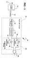
- an interference detection assembly is generally indicated at 10.
- the interference detection assembly 10 detects interference generated from a plurality of signals received by a receiver (not shown) having a single output signal.
- the plurality of signals received on a specific carrier frequency generates the co-channel interference phenomenon which may be interpreted by the receiver of an audio system (not shown) as a pilot tone indicating a stereo signal.
- the interference detection assembly 10 includes a synchronous demodulator 14.
- the synchronous demodulator 14 includes an input line 16 electrically connected to the receiver to receive the single output signal therefrom.
- the synchronous demodulator 14 converts the single output signal to generate a zero Hertz (0 Hz) intermediate frequency signal.
- the intermediate frequency signal is output from the synchronous demodulator 14 through a Q-channel output line 18.
- the output along the Q-channel output line 18 is a quadrature or phase modulation of the single output signal.
- the interference detection assembly 10 includes a pilot detector 20 electrically connected to the Q-channel output line 18.
- the pilot detector 20 receives the phase of the output signal to detect co-channel interference.
- the pilot detector 20 includes a band pass filter 22 which directly receives the phase of the single output signal from the Q-channel output line 18.
- the band pass filter 22 defines a predetermined frequency band through which only signals having a frequency at or near that predetermined frequency may pass therethrough. In one embodiment, the predetermined frequency is 25 Hz and a Q of approximately eight.
- the pilot detector 20 also includes a comparator stage 26.
- the comparator stage 26 compares the average signal to threshold signals.
- the comparator stage 26 includes a high comparator 28 and a low comparator 30.
- the high comparator 28 compares the averaged signal against a high threshold signal input 32
- the low comparator 30 compares the average signal against a low threshold signal input 34.
- the high threshold signal is fifty percent higher than the desired phase-modulated level and the low threshold signal is fifty percent below the desired phase-modulated level. Therefore, the threshold is from 2.5 percent to 7.5 percent of the maximum phase modulation of one radian.
- An AND gate 36 receives the output from each of the high comparator 28 and the low comparator 30. As should be well known to those skilled in the art, the output of the AND gate 36 will be a logic "high,” indicating a valid pilot detection, when both outputs of the high comparator 28 and the low comparator 30 are a logic "high.”
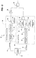
- the interference detection assembly 10' includes a co-channel detector 38.
- the co-channel detector 38 is connected to the synchronous demodulator 14' through an I-channel output line 40.
- the I-channel output line 40 is used to transmit the in-phase amplitude modulation of the signal received from the receiver. Because the pilot tone used to identify a stereo signal is phase modulation only, modulation on the Q-channel output line 18 is the only modulation which should be present. More specifically, the pilot tone is not part of the amplitude modulation and, therefore, the signal across the I-channel output line 40 should not contain a pilot signal. Therefore, if the co-channel detector 38 detects modulation at or near the pilot frequency, co-channel interference is most likely the reason for this modulation.
- the co-channel detector 38 includes a low pass filter 42. Because the frequency of interest is a low frequency, i.e., 25 Hz, the low pass filter 42 will only look at those modulations near 25 Hz. Once filtered, an integrator 44 averages the signal passed through the low pass filter 42. Once averaged, the signal is compared to a threshold signal from a threshold line 46 by a comparator 48.
- the output of the co-channel detector 38 is received by an inverter 50. Because the output of the pilot detector 20' is positive or a logic high when a pilot tone is present, the output of the co-channel detector 38 is inverted to allow an output AND gate 52 to provide a positive, non-interference, "stereo-enable" signal if co-channel interference does not exist. If, however, co-channel interference existed, the output of the co-channel detector 38 would be positive. Once inverted by the inverter 50, the output of the output AND gate 52 would be negative, or a logic "low,” identifying a situation as co-channel interference. If it is determined that co-channel interference exists, the audio system will be inhibited from entering into a stereo mode for the AM signal received by the receiver.
- a third embodiment of a co-channel interference detection assembly is generally indicated at 10''.
- the co-channel detector 38'' includes two inputs, one from the I-channel output line 40'' and one from the Q-channel output line 18''. Each input is passed through a low pass filter 42'', 54. The outputs of the low pass filters 42'', 54 are correlated by a correlator 56. The correlation performed by the correlator 56 tests for modulation in the I-channel output line 40'' relative to modulation in the Q-channel output line 18''.
- phase correlation If little or no phase correlation exists, a pilot tone may be present, but is being distorted by poor receiving conditions. If, however, there is a certain degree of phase correlation between the I-channel output line 40'' and the Q-channel output line 18'', then low frequency modulation of the I-channel output line 40'' represents co-channel interference is occurring and the audio system will be inhibited from entering a stereo mode.
Landscapes
- Engineering & Computer Science (AREA)
- Computer Networks & Wireless Communication (AREA)
- Signal Processing (AREA)
- Noise Elimination (AREA)
- Monitoring And Testing Of Transmission In General (AREA)
- Stereo-Broadcasting Methods (AREA)
Applications Claiming Priority (2)
| Application Number | Priority Date | Filing Date | Title |
|---|---|---|---|
| US783722 | 1997-01-16 | ||
| US08/783,722 US5784466A (en) | 1997-01-16 | 1997-01-16 | Co-channel interference detector |
Publications (2)
| Publication Number | Publication Date |
|---|---|
| EP0854598A2 true EP0854598A2 (de) | 1998-07-22 |
| EP0854598A3 EP0854598A3 (de) | 2004-11-17 |
Family
ID=25130199
Family Applications (1)
| Application Number | Title | Priority Date | Filing Date |
|---|---|---|---|
| EP97310729A Withdrawn EP0854598A3 (de) | 1997-01-16 | 1997-12-31 | Detektor der gegenseitigen Interferenzen für einen Rundfunkempfänger |
Country Status (4)
| Country | Link |
|---|---|
| US (1) | US5784466A (de) |
| EP (1) | EP0854598A3 (de) |
| JP (1) | JPH10209991A (de) |
| CA (1) | CA2226092A1 (de) |
Cited By (3)
| Publication number | Priority date | Publication date | Assignee | Title |
|---|---|---|---|---|
| WO2004068757A1 (ja) | 2003-01-31 | 2004-08-12 | Matsushita Electric Industrial Co., Ltd. | Ofdm信号の衝突位置検出装置及びofdm受信装置 |
| EP1619804A3 (de) * | 2004-07-22 | 2006-04-12 | Robert Bosch Gmbh | Gerät zum Empfang von frequenzmodulierten Rundfunksignale |
| CN102735946A (zh) * | 2012-07-05 | 2012-10-17 | 山东华芯半导体有限公司 | 一种消除信号采样中干扰的方法 |
Families Citing this family (5)
| Publication number | Priority date | Publication date | Assignee | Title |
|---|---|---|---|---|
| US5933768A (en) * | 1997-02-28 | 1999-08-03 | Telefonaktiebolaget L/M Ericsson | Receiver apparatus, and associated method, for receiving a receive signal transmitted upon a channel susceptible to interference |
| US6312645B1 (en) | 1998-12-30 | 2001-11-06 | Ethicon, Inc. | Container with collapsible pouch for cleaning or sterilization |
| US6760366B1 (en) * | 1999-11-29 | 2004-07-06 | Qualcomm Incorporated | Method and apparatus for pilot search using a matched filter |
| JP4349865B2 (ja) * | 2003-08-29 | 2009-10-21 | 三洋電機株式会社 | Am受信回路 |
| CN115001610B (zh) * | 2022-06-02 | 2024-05-03 | 高新兴物联科技股份有限公司 | 干扰检测方法及装置、通信设备及存储介质 |
Citations (1)
| Publication number | Priority date | Publication date | Assignee | Title |
|---|---|---|---|---|
| US4845750A (en) * | 1987-11-16 | 1989-07-04 | Motorola, Inc. | Multiple function control circuit for an AM stereo receiver |
Family Cites Families (4)
| Publication number | Priority date | Publication date | Assignee | Title |
|---|---|---|---|---|
| JPS57155852A (en) * | 1981-03-20 | 1982-09-27 | Sony Corp | Stereo reproducing device |
| US4426728A (en) * | 1981-08-31 | 1984-01-17 | Kahn Leonard R | Multiple system AM stereo receiver and pilot signal detector |
| US4504966A (en) * | 1983-05-31 | 1985-03-12 | Harris Corporation | Stereo inhibitor for AM stereo receiver |
| US5023909A (en) * | 1989-09-25 | 1991-06-11 | Kahn Leonard R | Multi-system AM stereo receiver having preferred mode of operation |
-
1997
- 1997-01-16 US US08/783,722 patent/US5784466A/en not_active Expired - Lifetime
- 1997-12-31 EP EP97310729A patent/EP0854598A3/de not_active Withdrawn
-
1998
- 1998-01-05 CA CA002226092A patent/CA2226092A1/en not_active Abandoned
- 1998-01-16 JP JP10006911A patent/JPH10209991A/ja active Pending
Patent Citations (1)
| Publication number | Priority date | Publication date | Assignee | Title |
|---|---|---|---|---|
| US4845750A (en) * | 1987-11-16 | 1989-07-04 | Motorola, Inc. | Multiple function control circuit for an AM stereo receiver |
Cited By (5)
| Publication number | Priority date | Publication date | Assignee | Title |
|---|---|---|---|---|
| WO2004068757A1 (ja) | 2003-01-31 | 2004-08-12 | Matsushita Electric Industrial Co., Ltd. | Ofdm信号の衝突位置検出装置及びofdm受信装置 |
| EP1583268A4 (de) * | 2003-01-31 | 2011-05-11 | Panasonic Corp | Ofdm-signalkollisionspositionsdetektionseinrichtung undofdm-empfangseinrichtung |
| EP1619804A3 (de) * | 2004-07-22 | 2006-04-12 | Robert Bosch Gmbh | Gerät zum Empfang von frequenzmodulierten Rundfunksignale |
| CN102735946A (zh) * | 2012-07-05 | 2012-10-17 | 山东华芯半导体有限公司 | 一种消除信号采样中干扰的方法 |
| CN102735946B (zh) * | 2012-07-05 | 2014-12-03 | 山东华芯半导体有限公司 | 一种消除信号采样中干扰的方法 |
Also Published As
| Publication number | Publication date |
|---|---|
| US5784466A (en) | 1998-07-21 |
| JPH10209991A (ja) | 1998-08-07 |
| CA2226092A1 (en) | 1998-07-16 |
| EP0854598A3 (de) | 2004-11-17 |
Similar Documents
| Publication | Publication Date | Title |
|---|---|---|
| US6253067B1 (en) | Transmitter/receiver having an antenna failure detection system | |
| EP0810738A3 (de) | Empfangsverfahren und Empfangsvorrichtung | |
| HK1040328A1 (zh) | 干擾檢測和消除技術 | |
| US5598430A (en) | Analog/digital receiver | |
| US5784466A (en) | Co-channel interference detector | |
| US4426728A (en) | Multiple system AM stereo receiver and pilot signal detector | |
| US4489431A (en) | Signal interference protection circuit for AM stereo receiver | |
| EP0991236A2 (de) | Vorrichtung und Verfahren zur Schätzung der Zentralfrequenz eines Empfangssignals | |
| US6094451A (en) | Radio receiver using level-variable reference, signal for discriminative detection of data signal and signal discrimination method | |
| GB2105130A (en) | Synchronous AM envelope detector | |
| EP1061654B1 (de) | Rauschdetektion in einem Frequenzdemodulierten FM Rundfunksignal | |
| US4504966A (en) | Stereo inhibitor for AM stereo receiver | |
| JPH03278733A (ja) | バースト位置検出装置 | |
| US5046129A (en) | Reducing phase error in received FM multiplex signal | |
| US4466116A (en) | Signal processor for AM stereophonic receiving apparatus | |
| US5894593A (en) | Method and apparatus for enhancing the detection of the presence of an FM signal using a coded pattern | |
| JPS6359612B2 (de) | ||
| EP0293828B1 (de) | Schaltungsanordnung zum Demodulieren DSB-modulierter Signale und Verfahren dafür | |
| JP2531377B2 (ja) | 変調方式識別回路 | |
| US6389089B1 (en) | Method of searching for pilot signals | |
| US7457420B2 (en) | Method and system for detecting signal modes in a broadcast audio transmission | |
| US6449321B1 (en) | Radio receiver | |
| US6658241B1 (en) | Radio receiver automatic frequency control techniques | |
| JPS5843303Y2 (ja) | Amステレオ受信機 | |
| USRE33381E (en) | Multiple system AM stereo receiver and pilot signal detector |
Legal Events
| Date | Code | Title | Description |
|---|---|---|---|
| PUAI | Public reference made under article 153(3) epc to a published international application that has entered the european phase |
Free format text: ORIGINAL CODE: 0009012 |
|
| AK | Designated contracting states |
Kind code of ref document: A2 Designated state(s): AT BE CH DE DK ES FI FR GB GR IE IT LI LU MC NL PT SE |
|
| AX | Request for extension of the european patent |
Free format text: AL;LT;LV;MK;RO;SI |
|
| PUAL | Search report despatched |
Free format text: ORIGINAL CODE: 0009013 |
|
| AK | Designated contracting states |
Kind code of ref document: A3 Designated state(s): AT BE CH DE DK ES FI FR GB GR IE IT LI LU MC NL PT SE |
|
| AX | Request for extension of the european patent |
Extension state: AL LT LV MK RO SI |
|
| 17P | Request for examination filed |
Effective date: 20050408 |
|
| AKX | Designation fees paid |
Designated state(s): DE GB NL |
|
| 17Q | First examination report despatched |
Effective date: 20050705 |
|
| STAA | Information on the status of an ep patent application or granted ep patent |
Free format text: STATUS: THE APPLICATION IS DEEMED TO BE WITHDRAWN |
|
| 18D | Application deemed to be withdrawn |
Effective date: 20070703 |