EP0854648A2 - Signalerzeuger zur Einfügung von Daten in digitale Fernsehesignale - Google Patents
Signalerzeuger zur Einfügung von Daten in digitale Fernsehesignale Download PDFInfo
- Publication number
- EP0854648A2 EP0854648A2 EP98100544A EP98100544A EP0854648A2 EP 0854648 A2 EP0854648 A2 EP 0854648A2 EP 98100544 A EP98100544 A EP 98100544A EP 98100544 A EP98100544 A EP 98100544A EP 0854648 A2 EP0854648 A2 EP 0854648A2
- Authority
- EP
- European Patent Office
- Prior art keywords
- vbi
- data
- transition
- syntax
- symbol
- Prior art date
- Legal status (The legal status is an assumption and is not a legal conclusion. Google has not performed a legal analysis and makes no representation as to the accuracy of the status listed.)
- Withdrawn
Links
Images


Classifications
-
- H—ELECTRICITY
- H04—ELECTRIC COMMUNICATION TECHNIQUE
- H04N—PICTORIAL COMMUNICATION, e.g. TELEVISION
- H04N7/00—Television systems
- H04N7/08—Systems for the simultaneous or sequential transmission of more than one television signal, e.g. additional information signals, the signals occupying wholly or partially the same frequency band, e.g. by time division
- H04N7/087—Systems for the simultaneous or sequential transmission of more than one television signal, e.g. additional information signals, the signals occupying wholly or partially the same frequency band, e.g. by time division with signal insertion during the vertical blanking interval only
- H04N7/088—Systems for the simultaneous or sequential transmission of more than one television signal, e.g. additional information signals, the signals occupying wholly or partially the same frequency band, e.g. by time division with signal insertion during the vertical blanking interval only the inserted signal being digital
-
- H—ELECTRICITY
- H04—ELECTRIC COMMUNICATION TECHNIQUE
- H04N—PICTORIAL COMMUNICATION, e.g. TELEVISION
- H04N7/00—Television systems
- H04N7/015—High-definition television systems
-
- H—ELECTRICITY
- H04—ELECTRIC COMMUNICATION TECHNIQUE
- H04N—PICTORIAL COMMUNICATION, e.g. TELEVISION
- H04N21/00—Selective content distribution, e.g. interactive television or video on demand [VOD]
- H04N21/20—Servers specifically adapted for the distribution of content, e.g. VOD servers; Operations thereof
- H04N21/23—Processing of content or additional data; Elementary server operations; Server middleware
- H04N21/235—Processing of additional data, e.g. scrambling of additional data or processing content descriptors
-
- H—ELECTRICITY
- H04—ELECTRIC COMMUNICATION TECHNIQUE
- H04N—PICTORIAL COMMUNICATION, e.g. TELEVISION
- H04N21/00—Selective content distribution, e.g. interactive television or video on demand [VOD]
- H04N21/40—Client devices specifically adapted for the reception of or interaction with content, e.g. set-top-box [STB]; Operations thereof
- H04N21/43—Processing of content or additional data, e.g. demultiplexing additional data from a digital video stream; Elementary client operations, e.g. monitoring of home network or synchronising decoder's clock; Client middleware
- H04N21/435—Processing of additional data, e.g. decrypting of additional data, reconstructing software from modules extracted from the transport stream
Definitions
- the present invention relates to the communication of digital television signals, and more particularly to a waveform generator useful for providing a digital television signal with data of a type conventionally carried in the vertical blanking interval (VBI) of an analog television signal.
- data hereinafter referred to as "user data”
- closed caption data CC
- VITC vertical interval time code
- non-realtime video data e.g., vertical interval test signals - VITS
- sampled video data North American Basic Teletext Specification (NABTS), World System Teletext (WST), European Broadcast Union (EBU) data and Nielsen Automated Measurement of Lineup (AMOL) data.
- NABTS North American Basic Teletext Specification
- WST World System Teletext
- EBU European Broadcast Union
- AMOL Nielsen Automated Measurement of Lineup
- Digital transmission of television signals can deliver video and audio services of much higher quality than analog techniques.
- Digital transmission schemes are particularly advantageous for signals that are broadcast via a cable television network or by satellite to cable television affiliates and/or directly to home satellite television receivers. It is expected that digital television transmitter and receiver systems will replace existing analog systems just as digital compact discs have replaced analog phonograph records in the audio industry.
- One way to transmit the compressed video data to a receiver is in the form of packets contained within a packetized data stream.
- packets carrying compressed video data are multiplexed with other packets, e.g., carrying corresponding audio data and control information necessary to reconstruct a television signal.
- One standard for transporting digital television signals in this manner is the MPEG-2 standard, details of which can be found in the International Organisation for Standardisation, ISO/IEC 13818-1, International Standard, 13 November 1994 entitled “Generic Coding of Moving Pictures and Associated Audio: Systems," recommendation H.222.0, incorporated herein by reference.
- ATSC Advanced Television Systems Committee
- A/53 Another standard for transporting digital television data in a packet stream is the Advanced Television Systems Committee (ATSC) Digital Television Standard A/53, approved on April 12 and September 15, 1995, incorporated herein by reference.
- ATSC Digital Television Standard is based on the ISO/IEC MPEG-2 Video Standard, the Digital Audio Compression (AC-3) Standard, and the ISO/IEC MPEG-2 Systems Standard.
- a transport stream, or transport multiplex is made up of a contiguous set of fixed length packets.
- the video sequence is transported using a hierarchical structure in which a sequence header is followed by various extensions, user data, a group of pictures ("GOP") header, optional user data, a picture header, etc.
- the sequence header provides information for a sequence of pictures, which in general will include more than one GOP. This information includes, for example, horizontal and vertical size values, aspect ratio, frame and bit rate, and quantization parameters for the video data.
- a user data extension can also be included which, among other things, provides additional data for use by decoders.
- the DigiCipher® II standard provides for the transport of additional user data after the sequence header, in order to identify a DigiCipher® II signal and the use of any special video compression techniques used within a sequence, including DigiCipher® special prediction and block motion estimation.
- a sequence display extension containing, e.g., video format and color description information, is provided in addition to the sequence extension and user data.
- a subsequent group of pictures header provides, among other information, a time code.
- a picture header is provided which includes various information pertaining to a corresponding picture in a sequence of pictures to be displayed.
- a picture extension and, ultimately, the actual picture data to be decoded and reproduced for viewing, is then provided.
- MPEG does not specify the order in which various extensions (such as the sequence display extension) or the user data must be transmitted beyond the fact that they must be after the sequence extension and before the GOP header (if provided) or the picture header.
- MPEG does not require GOP headers to be sent, and such headers may be bypassed in particular implementations.
- VBI vertical blanking interval
- VBI waveforms The character of VBI waveforms is very different compared to active video. Transmission without compression for these lines is very bandwidth intensive, such as sending 8 or 10 bit samples of 704 or 720 luminance and chrominance pixels. For example, 720 luminance and chrominance values at 8 bit resolution and 30 Hz requires 345,600 bps while the information conveyed by these lines only represents 480 bps for closed captions and 6720 bps for North American Basic Teletext Specification. As the transition to digital video proceeds, the demand for carriage and reconstruction of VBI services continues. Digital video distribution systems are expected to reconstruct the VBI as well as the active video, even when digital video compression techniques are employed. Thus, there is a need for algorithms, syntax and semantics specifically for the compression of VBI video lines that will allow an efficient and flexible alternative to developing VBI-waveform specific user data syntax and semantics.
- apparatus for generating digital waveforms complying with different vertical blanking interval (VBI) services for insertion into VBI portions of a digital component video signal.
- VBI vertical blanking interval
- a buffer receives a plurality of symbols carrying VBI data for a particular VBI service according to a user data syntax, which identifies a television line into which the VBI data is to be inserted.
- a timing circuit is responsive to a start time (provided by the syntax) for a first one of the symbols to effect the insertion of the VBI data into the VBI portion of the digital component video signal at a time dictated by the particular VBI service.
- a symbol processor is responsive to information provided by the syntax.
- This information indicates (i) a number of pixels represented per symbol, (ii) a transition time for the symbols, and (iii) the number of symbols carrying data to be inserted into the VBI portion.
- the symbol processor provides the VBI data in a format dictated by the particular VBI service.
- a level control circuit may be provided to adjust the level of the VBI data prior to insertion into the VBI portion in response to at least one amplitude value provided by the syntax. Multilevel amplitude modulation of the VBI data may optionally be provided.
- the symbol processor comprises a transition processor for detecting a transition in the VBI data, and generating a transition waveform in response to the detected transition.
- the transition waveform complies with the format dictated by the particular VBI service.
- Means are provided for combining the transition waveform with the VBI data to provide the digital waveform for insertion into the VBI portion of the television line identified by the syntax.
- the transition processor may further include a memory for storing transition data for generating the transition waveforms.
- the transition waveform may be a ramp or a non-linear function, for example.
- the symbol processor implements a finite impulse response (FIR) function (equivalent, e.g., to an FIR filter) for generating a data symbol sequence which represents the VBI data for the particular VBI service for insertion into the VBI portion of the television line identified by the syntax.
- FIR finite impulse response
- a memory may also be provided for storing finite impulse response data for the VBI services according to a transition type of the VBI services which is defined by the syntax, where the means for implementing is responsive to the stored finite impulse response data for implementing the finite impulse response function for the particular VBI service.
- an infinite impulse response (IIR) filter or equalizer may be used.
- the filter may be implemented in a look-up table.
- the impulse response data may be downloaded to the memory in conjunction with the VBI service or independently.
- the first and second embodiments may be realized in a single implementation.
- the present invention provides a bandwidth efficient method and apparatus for using a digital television data stream to transport variable amounts of different types of information conventionally carried in the VBI portion of an analog television signal.
- the information of concern is a subset of a type of user data referred to as "picture user data" to distinguish it from “sequence user data" in an MPEG, ATSC or DigiCipher® II transport stream.
- This subset referred to herein as VBI user information, comprises information such as closed caption data, sampled video data, NABTS, WST, EBU data and Nielsen AMOL data.
- Each of these categories of picture user data is updated each picture.
- the picture user data is transported in portions of successive video frames which correspond to VBI lines.
- Each VBI line is represented by 720 eight-bit luminance samples and 720 eight-bit chrominance samples before processing in accordance with the present invention.
- VBI waveforms can be represented as pulse amplitude modulated (PAM) data (e.g., such as non-return-to-zero (NRZ) data) modulated onto the luminance portion of a video signal.
- PAM pulse amplitude modulated
- NRZ non-return-to-zero
- Such waveforms can be classified by their pulse shape, number of pixels per symbol, symbol-to-risetime ratio, waveform start time within the video line, and applicable video system (i.e., video standard). Since none of the standards specify significant line-to-line or frame-to-frame correlation of data, each VBI line can be processed independently of any other VBI line.
- the pulse shape specifications allow the different VBI waveforms to be categorized into waveforms that require a pulse shape of less than one symbol time in duration (such as non-Teletext waveforms) and waveforms that require a pulse shape of more than one symbol time (such as Teletext waveforms).
- the present invention capitalizes on the realizations set forth above with respect to the various different VBI waveform formats to provide a waveform generator which is compatible with various types of VBI data which is communicated in a digital television data stream.
- a single state machine is provided that is able to reconstruct most of the various VBI waveforms.
- the state machine allows the following parameters to be programmable: the field number of the particular VBI line, the line number of the particular VBI line, the symbol rate used by the particular VBI waveform standard, the standard's CCIR-601 start sample number, the standard's risetime (symbol to transition duration ratio), the standard's CCIR-601 value for NRZ "0" and “1” symbols, the number of symbols in the standard's waveform, and the vector of values of the symbols in the particular VBI line's waveform.
- CCIR-601 is a standard, promulgated by the International Radio Consultive Committee for digital component coding and filtering.
- VBI service is used herein to refer to any of the listed standards as well as any other VBI data format, protocol or system.
- the standards listed apply to either 525-line (NTSC and PAL/M) or 625-line (PAL excepting PAL/M) video Systems.
- NTSC and PAL/M 625-line
- PAL excepting PAL/M 625-line
- Each standard provides some portion of the waveform as a Timing Reference and Sync Pattern for the purpose of symbol synchronization.
- each provides a fixed number of Data Bits per video line, some of which may be provided for the purpose of Error Detection.
- Each modulates the data bits onto the video line via some Modulation technique and employing different Amplitudes to represent different data bit values.
- each waveform employs a nominal Symbol Rate (sometimes referenced to the video line rate [fh]) and Pulse (symbol) Shape (often specified with a rise time [tr] or Raised Cosine pulse shape with a particular value of Alpha).
- Symbol Rate sometimes referenced to the video line rate [fh]
- Pulse symbol Shape
- tr rise time
- Raised Cosine pulse shape with a particular value of Alpha
- a state machine providing programmability of the above parameters for use in reconstructing each of the various VBI waveforms is disclosed below in connection with FIGURE 3.
- the novel syntax in accordance with the present invention is disclosed in conjunction with an example embodiment of an encoder and decoder structure.
- FIGURE 1 illustrates, in block diagram form, an encoder for processing raw digital video data into a user data syntax in which variable amounts of different types of VBI user information can be communicated in a digital television data stream.
- the user data syntax may include PAM data, such as NRZ data, referred to herein as "luma NRZ". It will be appreciated that while NRZ data is referred to in particular illustrative examples, other PAM schemes may be used.
- the raw digital video such as video complying with the Society of Motion Picture and Television Engineers (SMPTE) standard is input to a serial receiver 12 via terminal 10.
- the serial receiver serializes the data which is input in a parallel format.
- the serialized data is buffered in a buffer 14, which can comprise a conventional first-in first-out (FIFO) register.
- a video parser 16 interprets the syntax of the serialized data and strips out various information such as that identifying the start of a new line, the start of a new frame, and the raw luminance and chrominance data.
- the luminance and chrominance data is input to a demultiplexer 18 where it is separated into data portions corresponding to vertical blanking intervals of successive video frames (e.g., lines 1-21 of a counterpart NTSC analog television signal) and the active video portions of those frames.
- Demultiplexer 18 also determines if synchronization of the acquired data stream has been lost, and if so, outputs a "sync loss" signal to a video compression processor 22, which also receives the active video to be compressed.
- the video compression processor is a type well known in the art, such as described in U.S. patents 5,376,968; 5,235,419; 5,091,782; or 5,068,724.
- VBI data some types of user data which is classified as VBI data may not reside in the actual VBI.
- programming lineup information used by the A.C. Nielsen Company for market research and referred to as "Automated Measurement of Lineup” (AMOL) is inserted into line 22 of field 2 of each television frame in the National Television Systems Committee (NTSC) broadcasting standard.
- Line 22 is an active video line, and thus a decoder may commence processing active video with line 23 instead of line 22 for NTSC signals.
- the AMOL line for each frame will typically be present, but the data for most frames will generally be null.
- the VBI is assumed to extend to line 22 instead of line 21.
- the data contained in the VBI portions of the digital video input signal is output from demultiplexer 18 to random access memories (RAMs) 20, which include both a luminance RAM and a chrominance RAM.
- RAMs random access memories
- the RAMs store the data until required by a syntax processor 24 which extracts the VBI user information and builds a syntax enabling the information to be transported efficiently in the VBI portions of a digital television data stream to be communicated to a corresponding decoder, e.g., at an end user location.
- the syntax provided by the syntax processor is stored in a header FIFO 28, which is used to assemble transport headers for, e.g., an MPEG or DigiCipher® II implementation of the digital television data stream.
- the header FIFO provides the syntax information to a barrel shifter 30 that combines the header with the compressed active video from a video coder 26.
- the video coder 26 codes the compressed video from the video compression processor 22 in a well known manner using, for example, Huffman coding to provide codewords (CW), codeword lengths (CL) and data tags which identify the coded information.
- the output from barrel shifter 30 is a data stream containing the active video separated by headers which contain information necessary to decode the active video.
- This data stream is stored in a video buffer 32 which provides the data on an as needed basis to a packetizer 34.
- the packetizer is a conventional component which assembles the data into transport packets in accordance with a transport stream standard such as the ATSC, MPEG-2 or DigiCipher® II digital television standard.
- This grammar is a C-language-like syntax and is a method of describing continuous and possibly variable rate sequences of bits, instead of specifying a procedural program and its functions as in the computer language C.
- the first column of the syntax contains the syntax element.
- the second column gives the length of the syntax elements in bits and the third column identifies the syntax type.
- the types are bslbf (bit string left-most bit first) and uimsbf (unsigned integer most significant bit first).
- the header "user_data () ⁇ ... ⁇ ” indicates that the syntax elements within the braces are a named set and may be invoked elsewhere in the syntax by simply using the designation "user_data ()".
- a conditional occurrence of bit structures may be indicated with the usual "if" tests.
- the customary relational operators well known in the C-language are also available. Loop structures are possible and use the standard C loop header syntax.
- the syntax table is accompanied by a set of semantics, providing definitions for each previously undefined syntax field and placing constraints on their use.
- the following picture user data bitstream syntax in which the shaded areas represent the standard ATSC user data syntax and the non-shaded areas represent the syntax in accordance with the present invention) and bitstream semantics illustrate a preferred embodiment of the present invention:
- the above syntax is assembled by the syntax processor 24 illustrated in FIGURE 1.
- the syntax processor is implemented in firmware. After the syntax is added to the digital video data, the resultant data stream is packetized and output from packetizer 34 to provide the final transport stream for communication to a population of decoders.
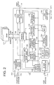
- FIGURE 2 is a block diagram of a video decompression processor (i.e., decoder) for processing a received data stream that contains the VBI user data syntax detailed above.
- the video decompression processor incorporates a memory manager 130 that addresses a DRAM 122 to store and retrieve video data necessary to reconstruct a television program at a receiver.
- the processor generally designated 120, is a pipelined processor designed to decode both the transport layer (i.e., control and other non-video information) and the video layer of the compressed bitstream input via terminal 110, sometimes referred to as the "transport packet interface" of the video processor.
- a user processor interface which can comprise, for example, an M-bus controller 150 is provided at terminal 114 for control of the video data processor. This interface configures various registers in processor 120 as well known in the art.
- DRAM 122 An interface to the DRAM 122 is provided via address lines 124 and data lines 126.
- DRAM 122 has a nine bit address port and a thirty-two bit data port.
- a video output interface 138 is provided for the decompressed, reconstructed video which may, for example, be output as a standard CCIR 656, eight bit, twenty-seven MHz multiplexed luminance (Y) and chrominance (Cr, Cb) signal.
- a test interface can be provided via terminal 162 to a conventional JTAG (Joint Test Action Group) controller 160.
- JTAG is a standardized boundary scan methodology used for board-level testing to detect faults in package and board connections, as well as internal circuitry.
- the video decompression processor 120 receives a clock signal via terminal 112.
- the clock provides timing information that is used, e.g., to enable a transport syntax parser 132 to recover timing information and video information from transport packets contained in a packetized data stream input via terminal 110.
- An acquisition and error management circuit 134 utilizes a program clock reference (PCR) and decode time stamp (DTS) detected by a video syntax parser 140 to synchronize the start of picture decoding. This circuit sets vertical synchronization and provides global synchronization for all video decode and display functions.
- PCR program clock reference
- DTS decode time stamp
- the video layer is buffered in an input buffer (FIFO) configured in the DRAM 122 by memory manager 130.
- the video syntax parser 140 receives the compressed video data output from the DRAM FIFO via memory manager 130, and separates the motion vector information from the coefficients describing the video information.
- the coefficients are processed by a Huffman decoder 152, inverse quantizer 154, and inverse discrete cosine transform (IDCT) processor 156.
- FIFO input buffer
- IDCT inverse discrete cosine transform
- Motion vectors are recovered and used to address previously decoded video frames required for reconstructing a current video frame.
- a motion vector decoder 142 decodes the motion vectors received from video syntax parser 140 and passes them to a prediction address generator 144.
- the prediction address generator provides address information necessary to retrieve, via memory manager 130, the necessary anchor frame (i.e., intraframe (I) or prediction (P) frame) data to enable prediction calculator 146 to provide a prediction signal necessary to reconstruct a current frame block.
- Differential decoder 148 combines the prediction data with the decoded coefficient data to provide decompressed video data.
- the decompressed data is stored in appropriate buffers of DRAM 122 via memory manager 130.
- Memory manager 130 schedules all activity on the DRAM address and data buses 124, 126 and efficiently addresses DRAM 122.
- the memory manager insures that the data transfer requirements of the input FIFO portion of DRAM 122, the video syntax parser 140 and the video reconstruction circuit 136 (as well as prediction calculator 146 and differential decoder 148) are all met.
- the video reconstruction circuit 136 calculates a current picture and processes the VBI user data in order to insert the desired user data for output on video output line 138. It should be appreciated that user data other than VBI user data may also be present, and that user data that is available may be stored temporarily before being processed and output.
- the video output 138 will contain the processed VBI user information together with the decompressed active video, in the original format presented to the serial receiver 12 illustrated in FIGURE 1.
- DRAM 122 is illustrated as an external memory. It should be appreciated that in future implementations, and as memory technology advances, DRAM 122 may be provided as internal memory within the video decompression processor. The DRAM is mapped to provide various decode and output video buffers as well as a circular FIFO buffer for the compressed input video bitstream. The DRAM may also be used to provide a test pattern buffer, a VITS buffer and a closed captioning display reordering buffer as well as to store various picture structure data necessary to properly display the decoded video frames. The DRAM can be reinitialized via memory manager 130 to provide different memory maps as required when variables are modified such as PAL or NTSC video, eight or sixteen Mbit memory configuration, and whether B-frames are present.
- the memory manager 130 schedules all of the activity on the DRAM buses including the data transfer requirements of the input FIFO, the video parser and the video reconstruction circuit.
- the memory manager also performs the required DRAM refresh in a conventional manner. For example, the same row in each of two or four DRAMs can be refreshed simultaneously.
- Video frames represented by the compressed data are reconstructed one at a time. Initially, a full frame of video data will have to be received and stored in DRAM 122. Information for subsequent video frames can comprise a subset of the full video frame which, when added to prediction data from the prior video frame (stored in DRAM 122) will result in the reconstruction of a full frame.
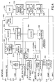
- FIGURE 3 is a block diagram of a pixel generator for generating a digital VBI waveform from user data carried in a digital video data stream according to the syntax set forth above.
- the waveform generator may be part of the video reconstruction circuit 136 of FIGURE 2, or may be provided independently of the video reconstruction circuit, e.g., for commercial applications where greater flexibility is desired albeit at potentially greater expense.
- the waveform generator is capable of accommodating the various parameters for the AMOL, VITC and EBU VBI standards set forth in Table 1. Each of these VBI services has a corresponding number of pixels per symbol.
- the closed caption, AMOL, VITC and EBU services have pulses with an impulse response time which is less than one symbol time, referred to herein as single symbol impulse response.
- the teletext services have a multisymbol impulse response, wherein the impulse response time is several symbols.
- a waveform generator for services having a multisymbol impulse response is described in FIGURE 4.
- the single symbol impulse response category of service has the characteristic that there are four or more pixels at CCIR 601 sampling rate per symbol. As can be seen from Table 5, closed caption has the maximum number of pixels per symbol (e.g., approximately 27). For single symbol impulse response services, there is no overlap from one symbol to the next.
- the time response of the symbol is characterized by its transition and the full amplitude portion.
- transition portion of a symbol can be downloaded as part of the service, or resident in a transition memory (ROM or RAM), such as provided in transition generator 218 in FIGURE 3.
- ROM transition memory
- RAM transition memory
- the use of ROM is more efficient in terms of hardware complexity and channel efficiency. A sine squared transition will work for all of the various VBI services.
- Data to be inserted into a VBI waveform at a decoder is inserted via a symbol input 200 and queued in a FIFO 202.
- the data is inserted into the VBI by playing back the symbols through a pixel generator.
- the pixel generator will be provided with the high and low levels to insert (0_amplitude and 1_amplitude) via terminal 201, the frame line number on which to insert the data (derived from field_number and line_offset) via terminal 203, the transition type (derived from pulse_shape) via terminal 205, the number of symbols to insert (derived from word_count and remainder_count) via terminal 207, the nrz_modulus and nrz_increment via terminals 209 and 211 respectively, the symbol_to_transition_ratio via terminal 213, and the start time of the first symbol (start_sample) via terminal 215. All of this information is specific to the particular type of VBI data to be inserted, and is provided via the syntax defined above.
- the video data is provided, for example, in a conventional CCIR 656 format and is coupled to a multiplexer 254.
- the multiplexer also receives a gating signal from an insertion window generator 248, which enables the multiplexer to output VBI data during a time window that is, for example, 704 pixels in length.
- a line count of the video data is maintained and compared to the desired line of insertion.
- This function is provided by a line detector 244 and line time generator 246 which receives the current line information from the video data via terminal 217.
- the line time generator 246 is enabled by line detector 244 when the line into which VBI data is to be inserted is detected by the line detector.
- the line time generator then keeps track of the pixels for that video line, and provides the video line pixel count to insertion window generator 248 in order to provide the proper insertion window of, e.g., 704 active pixels.
- the line time generator 246 Upon the arrival of a zero datum of the correct line, the line time generator 246 also signals a start time detector (counter) 214 which commences a down count for the start pixel time dictated by the start_sample information obtained from the syntax.
- the start pixel down counter 214 enables a symbol clock generator 210 which, in turn, clears a symbol counter 212.
- the symbol clock generator 210 receives the nrz_modulus and nrz_increment from the syntax. Once the symbol clock generator is started in response to detector 214, the symbol time is derived by incrementing a counter by the numerator of the fraction symbol time over pixel time. The modulus of the counter is the denominator of the fraction. If desired, the numerator and denominator may be multiplied by a constant to simplify the hardware implementation.
- the symbol clock generator 210 outputs a symbol clock to the FIFO enable for clocking the VBI data out from the FIFO 202. It also provides the fraction of symbol time that a current sample represents to a transition time scaling circuit 216, described below.
- the symbol clock runs until the symbol counter 212 counts the number of symbols specified by the word_count and remainder_count from the syntax, at which time a stop signal is generated. The stop signal also clears the shift register 206 in the VBI data path.
- transition sign detection circuit 208 The VBI data shifted through register 206 is monitored by a transition sign detection circuit 208. The presence or absence of a transition is detected by comparing the previous transmitted symbol with the current symbol to be transmitted. If they are the same, the same value is generated and transmitted. If there is a difference between the two symbols, then transition generator 218, which may comprise, for example, read only memory (ROM) or random access memory (RAM) is selected.
- ROM read only memory
- RAM random access memory
- the transition generator 218 stores data for generating multiple transition functions, one for each transition type that is supported, for the VBI data pulses for the different VBI standards.
- the particular transition function selected for the current VBI data is determined by the transition type specified by the pulse_shape value of the syntax and input to the transition generator 218 via terminal 205.
- the transition function may provide the pulse_shape as a rectangular or raised cosine pulse.
- the beginning and end of the transition are dictated by the addresses input to the transition generator from the transition time scaling circuit 216, which scales the fraction of symbol time in accordance with the symbol to transition duration ratio from terminal 213 and the nrz_modulus from terminal 209.
- the scaled fraction of the symbol time represents the position of the sample in time within the rise time of the VBI data pulse.
- the transition process is repeated until detection circuit 220 determines that the address exceeds the range of the transition generator ROM or RAM, at which time the symbol has reached 100 percent of its final value.
- An output multiplexer (selector) 242 selects the final value for the current and remainder of that symbol's pixels.
- Selection logic 222 controls the multiplexer 242 based on the initial detection of a transition by transition detection circuit 224 and the completion of the transition as determined by circuit 220.
- a look up table (LUT) 236 (stored, e.g., in ROM) converts each bit of data output from shift register 206 into an eight-bit level that is ultimately scaled to the proper luminance level for the particular type of user data being processed.
- LUT 236 can convert a binary "0" into the eight-bit word 00001111 and a binary "1" into the eight-bit word 1110000. This mapping is arbitrary, and any other desired eight-bit levels can be chosen for the binary "1" and "0".
- the eight-bit level from the output of LUT 236 is provided to multiplexer 242 which selects this level for output unless a transition is in progress as indicated by select logic 222, in which case the transition function from transition generator 218 is output.
- the data stream output from multiplexer 242 is then scaled to the required output levels in response to the 0_amplitude and 1_amplitude values delivered by the user data syntax via terminal 201.
- An output multiplexer 254 inserts the resultant VBI data on the video stream from terminal 217, for the insertion window provided by generator 248.
- the insertion window corresponds to the active video duration.
- VBI services can be inserted with the generator of FIGURE 3. Additional circuitry is necessary to load the variables required to run the generator on a line-by-line basis.
- the data is queued in a common FIFO. In the implementation shown, all clocks are running at 13.5 MHz, unless otherwise indicated. This is one-half the rate of the standard MPEG, ATSC and DigiCipher II system clock.
- EBU 3217 Data complying with EBU 3217 has the property that the transition time is slightly longer than the symbol time. This can be overcome by selecting a transition function that has a slower ten percent to ninety percent time relative to the entire transition.
- the specified filter for wave shaping EBU 3217 data is Gaussian transitional. A windowed Gaussian transition may provide better performance than sine squared.
- Teletext services can be supported in a similar manner as disclosed for the VBI services discussed in connection with FIGURE 3.
- the waveform generator must handle an impulse response which, as noted above, is greater in duration than one symbol.
- An example implementation of such a VBI waveform generator is illustrated in FIGURE 4.
- VBI Data FIFO 310 shift register 312, symbol counter 316, symbol clock generator 320, start time detect circuit 322, scale and offset circuit 306, multiplexer (selector) 308, insertion window generator 332, line detect circuit 330 and line time generator 328 of FIGURE 4 are equivalent to the similarly named elements in FIGURE 3.
- a transmit (Tx) filter ROM 302 and interpolation filter 314 are provided. It should be appreciated that the filter 302 can also be implemented in RAM if desired, particularly if the impulse response of the desired format is to be downloaded instead of being stored locally in ROM.
- Any such download will be at a fixed number of samples per symbol rate.
- the syntax for such a download can be provided according to the C-language-like syntax discussed previously.
- the interpolator is used to generate the 13.5 MHz rate pixels.
- the rate difference is the increment of the interpolator.
- the data to be inserted is queued in FIFO 310 via terminal 303.
- the data is inserted into the VBI by playing back the symbols through the pixel generator.
- the pixel generator is provided with the start time of the first symbol pixel via terminal 315, the number of pixels per symbol (increment/modulus) via terminals 311 and 309, the high and low levels (0_amplitude and 1_amplitude) to insert via terminal 300, the impulse response of the signaling system (transition type) via terminal 301, the number of symbols to insert via terminal 307, and the field and line number on which to insert the data via terminal 305.
- the video data input to terminal 317 is provided in CCIR 656 format.
- the line count is derived and compared to the desired line of insertion in circuits 330, 328 and 322.
- a down count for the start pixel time is started in circuit 322, which enables the symbol rate clock generator 320 at the appropriate time.
- the 704 pixel window generator 332 is enabled by the line time generator 328.
- symbol time is derived by incrementing a counter by the numerator of the fraction "symbol time/pixel time", where the increment "INCR” is the numerator and the modulus of the counter is the denominator of the fraction.
- the symbol clock generator 320 receives the system clock (e.g., 27 MHz) via terminal 313. By running the symbol clock generator at, e.g., 27 MHz rather than 13.5 MHz, a twice symbol rate clock is generated.
- the enable input of FIFO 310 receives the symbol clock from a divider 318, which divides the output of clock generator 320 by two. This is necessary because the symbol clock generator provides a clock at twice the symbol rate. Once the specified number of symbols has been output from the FIFO, the symbol clock is disabled for the current television line. All subsequent data symbols are forced to the low (zero) state. These symbols are not data, but rather fill the balance of the 704 pixel window with low state data.
- the transmit filter ROM 302 generates two samples per symbol.
- the transmit shift register 312 is loaded with transmit symbols at the symbol rate, when start time has arrived.
- the register is initialized to a low state on completion of each insertion.
- the transmit data for the duration of the impulse response is applied to the transmit ROM from shift register 312.
- the ROM stores a look up table of impulse responses computed in advance in accordance with well known techniques. By storing the results of the FIR calculation in the ROM, it is not necessary to store the FIR coefficients to calculate the results.
- the appropriate FIR for the particular transition to be provided in the VBI waveform is output from the LUT when the ROM is addressed by the transition type via terminal 301.
- the output of the transmit filter is provided to an interpolating filter 314 via register 304.
- the interpolation filter converts the 2 sample per symbol rate data to 13.5 MHz samples.
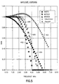
- the frequency response 400 of this interpolator (ParaIntr) and the transmit impulse responses 402, 404, 406 and 408 for the various teletext standards, as well as for the VideoCipher standard proprietary to the original assignee of the present invention, are illustrated in FIGURE 5. It can be seen that the interpolator clearly influences the transmitted frequency response. This frequency response error can be corrected (predistorted) in the transmit filter 302 to minimize its impact. It is a requirement that the transmit spectrum, and its images be well controlled prior to interpolation. This is the case for the described data signal types. If the pixel rate per symbol is less than about 3 samples per symbol, a greater number of samples per symbol would be required.
- the data supplied to the interpolator 314 is at twice symbol rate. The actual transfers of data occur coincident with the 27 MHz tick.
- the interpolator output is read at 13.5 MHz.
- the time interpolation variable is supplied to the filter at the 13.5 MHz rate.
- a time generator 324 and scaling circuit 326 allow the numerical representation of ⁇ to be consistent with the numerical system of the filter hardware, and independent of the current modulus value.
- the data stream has to be scaled to the required output levels. This can be accomplished, for example, with one multiply and addition per pixel provided by the scale and offset circuit 306.
- the output multiplexer 308 inserts the VBI data from the scale and offset circuit 306 on the CCIR video stream from terminal 317, for the 704 pixel window.
- M-level (multilevel) pulse amplitude modulation (PAM), with M ⁇ 2, can be supported using the waveform generator of FIGURE 4.
- PAM pulse amplitude modulation
- M>2 there would be log base 2 of M bits per symbol supplied to the transmit filter ROM.
- the present invention provides a method and apparatus for communicating user information in a digital television data stream.
- the user information is a type that is conventionally carried as NRZ data in the vertical blanking interval of an analog television signal.
- the user data is transported in a user data syntax, which has been supplemented with various fields. These include an additional data type field, a luma NRZ count and priority, field number, line offset, start sample, NRZ increment and modulus, amplitude values, pulse shape information, and word and remainder count information relating to the user data which is carried in the form of luma words and luma NRZ bits.
Landscapes
- Engineering & Computer Science (AREA)
- Multimedia (AREA)
- Signal Processing (AREA)
- Television Systems (AREA)
Applications Claiming Priority (4)
| Application Number | Priority Date | Filing Date | Title |
|---|---|---|---|
| US3539597P | 1997-01-16 | 1997-01-16 | |
| US35395P | 1997-01-16 | ||
| US887046 | 1997-07-02 | ||
| US08/887,046 US6160587A (en) | 1997-01-16 | 1997-07-02 | Waveform generator for insertion of data into digital television signals |
Publications (2)
| Publication Number | Publication Date |
|---|---|
| EP0854648A2 true EP0854648A2 (de) | 1998-07-22 |
| EP0854648A3 EP0854648A3 (de) | 1999-12-15 |
Family
ID=26712074
Family Applications (1)
| Application Number | Title | Priority Date | Filing Date |
|---|---|---|---|
| EP98100544A Withdrawn EP0854648A3 (de) | 1997-01-16 | 1998-01-14 | Signalerzeuger zur Einfügung von Daten in digitale Fernsehesignale |
Country Status (6)
| Country | Link |
|---|---|
| US (1) | US6160587A (de) |
| EP (1) | EP0854648A3 (de) |
| KR (1) | KR19980070568A (de) |
| CN (1) | CN1110199C (de) |
| CA (1) | CA2226588C (de) |
| TW (1) | TW369777B (de) |
Cited By (6)
| Publication number | Priority date | Publication date | Assignee | Title |
|---|---|---|---|---|
| EP0889655A3 (de) * | 1997-06-07 | 2000-05-31 | Philips Patentverwaltung GmbH | Digitaler Daten-Kodierer und Verfahren zur Datenkodierung |
| WO2000046989A1 (en) | 1999-02-05 | 2000-08-10 | Sony Corporation | Encoding device, encoding method, decoding device, decoding method, coding system and coding method |
| EP1091593A3 (de) * | 1999-10-08 | 2002-07-31 | ATI International SRL | Verfahren und Vorrichtung für verbesserte Videokodierung |
| WO2007081417A2 (en) | 2006-01-05 | 2007-07-19 | Thomson Licensing | Raw mode for vertical blanking internval (vbi) data |
| US7603025B2 (en) | 1999-05-21 | 2009-10-13 | Ati Technologies Srl | Method and apparatus for copy protection detection in a video signal |
| USRE44245E1 (en) | 1997-06-16 | 2013-05-28 | Ati Technologies Ulc | Method and apparatus for detecting protection of audio and video signals |
Families Citing this family (27)
| Publication number | Priority date | Publication date | Assignee | Title |
|---|---|---|---|---|
| US7099316B1 (en) * | 1996-02-29 | 2006-08-29 | Tomich John L | Photonic home area network |
| US6351289B1 (en) * | 1998-11-24 | 2002-02-26 | Winbond Electronics Corp. | Method and apparatus that generates VBI data coding waveforms |
| DE60028692T2 (de) * | 1999-05-20 | 2007-05-24 | Koninklijke Philips Electronics N.V. | Verfahren und anordnung zur übertragung und zum empfang von kodierten bildern |
| AU6920500A (en) * | 1999-08-20 | 2001-03-19 | Index Systems, Inc. | Vbi inserter |
| ES2558967T3 (es) * | 2000-04-06 | 2016-02-09 | Opentv, Inc. | Motor de tratamiento de datos genérico |
| US6694518B1 (en) * | 2000-05-30 | 2004-02-17 | Hughes Electronics Corporation | Method and apparatus for carrying data across high definition analog component video interfaces |
| US20020021760A1 (en) * | 2000-08-10 | 2002-02-21 | Harris Helen J. | Process for associating and delivering data with visual media |
| US20020118763A1 (en) * | 2000-08-10 | 2002-08-29 | Harris Helen J. | Process for associating and delivering data with visual media |
| US6466476B1 (en) * | 2001-01-18 | 2002-10-15 | Multi Level Memory Technology | Data coding for multi-bit-per-cell memories having variable numbers of bits per memory cell |
| US20020184653A1 (en) | 2001-02-02 | 2002-12-05 | Pierce Matthew D. | Services based on position location using broadcast digital television signals |
| US7319979B2 (en) * | 2001-03-29 | 2008-01-15 | Intel Corporation | Dynamically interacting with an internet service using a client-specified communication proxy and protocol |
| US6907081B2 (en) * | 2001-03-30 | 2005-06-14 | Emc Corporation | MPEG encoder control protocol for on-line encoding and MPEG data storage |
| US6727847B2 (en) * | 2001-04-03 | 2004-04-27 | Rosum Corporation | Using digital television broadcast signals to provide GPS aiding information |
| US7042949B1 (en) * | 2001-04-03 | 2006-05-09 | Rosum Corporation | Robust data transmission using broadcast digital television signals |
| KR100941196B1 (ko) | 2001-11-14 | 2010-02-10 | 더 로섬 코퍼레이션 | 디지털 텔레비전 신호를 이용한 gps 보조 정보 제공방법, 장치, 컴퓨터-판독형 매체 |
| US20040045038A1 (en) * | 2002-08-29 | 2004-03-04 | Duff John F. | System and method for the synchronized activation of external devices in association with video programs |
| TWI249955B (en) * | 2004-06-03 | 2006-02-21 | Realtek Semiconductor Corp | An apparatus and a method for receiving a digital signal |
| US7432981B1 (en) | 2004-12-13 | 2008-10-07 | Nvidia Corporation | Apparatus, system, and method for processing digital audio/video signals |
| US9679602B2 (en) | 2006-06-14 | 2017-06-13 | Seagate Technology Llc | Disc drive circuitry swap |
| US7990472B2 (en) * | 2007-04-25 | 2011-08-02 | Broadcom Corporation | Generalized VBI waveform generator |
| US9305590B2 (en) | 2007-10-16 | 2016-04-05 | Seagate Technology Llc | Prevent data storage device circuitry swap |
| US9277183B2 (en) * | 2009-10-13 | 2016-03-01 | Sony Corporation | System and method for distributing auxiliary data embedded in video data |
| US8659662B2 (en) * | 2009-10-14 | 2014-02-25 | Harris Corporation | Surveillance system with target based scrolling and related methods |
| US8587651B2 (en) * | 2009-10-14 | 2013-11-19 | Harris Corporation | Surveillance system for transcoding surveillance image files while retaining image acquisition time metadata and associated methods |
| US8477188B2 (en) * | 2009-10-14 | 2013-07-02 | Harris Corporation | Surveillance system for transcoding surveillance image files while retaining geospatial metadata and associated methods |
| TWI449434B (zh) * | 2011-09-30 | 2014-08-11 | Aten Int Co Ltd | 訊號傳輸裝置及其傳送器與接收器 |
| CN116612324B (zh) * | 2023-05-17 | 2025-12-23 | 四川九洲电器集团有限责任公司 | 基于语义自适应融合机制的小样本图像分类方法及装置 |
Family Cites Families (13)
| Publication number | Priority date | Publication date | Assignee | Title |
|---|---|---|---|---|
| US4862268A (en) * | 1980-03-31 | 1989-08-29 | General Instrument Corporation | Addressable cable television control system with video format data transmission |
| DE3273937D1 (en) * | 1981-03-20 | 1986-11-27 | Indep Broadcasting Authority | Decoder for digital information in a t.v. signal |
| US5289276A (en) * | 1992-06-19 | 1994-02-22 | General Electric Company | Method and apparatus for conveying compressed video data over a noisy communication channel |
| US5400401A (en) * | 1992-10-30 | 1995-03-21 | Scientific Atlanta, Inc. | System and method for transmitting a plurality of digital services |
| US5493339A (en) * | 1993-01-21 | 1996-02-20 | Scientific-Atlanta, Inc. | System and method for transmitting a plurality of digital services including compressed imaging services and associated ancillary data services |
| US5375160A (en) * | 1993-05-28 | 1994-12-20 | Ledler Corporation | Interface apparatus for effecting captioning and communications between a telephone line and a television |
| US5519780A (en) * | 1993-12-03 | 1996-05-21 | Scientific-Atlanta, Inc. | System and method for providing compressed digital teletext services and teletext support services |
| US5526427A (en) * | 1994-07-22 | 1996-06-11 | A.C. Nielsen Company | Universal broadcast code and multi-level encoded signal monitoring system |
| US5566089A (en) * | 1994-10-26 | 1996-10-15 | General Instrument Corporation Of Delaware | Syntax parser for a video decompression processor |
| JPH08298649A (ja) * | 1995-04-27 | 1996-11-12 | Oki Electric Ind Co Ltd | 映像符号化・復号化システム、映像符号化装置及び映像復号化装置 |
| US5555025A (en) * | 1995-06-07 | 1996-09-10 | Intel Corporation | Apparatus and method for performing asynchronous multi-standard VBI data extraction |
| US5699124A (en) * | 1995-06-28 | 1997-12-16 | General Instrument Corporation Of Delaware | Bandwidth efficient communication of user data in digital television data stream |
| CA2262368A1 (en) * | 1996-07-30 | 1998-02-05 | Tiernan Communications, Inc. | System and method for digitally encoding and compressing vbi signals |
-
1997
- 1997-07-02 US US08/887,046 patent/US6160587A/en not_active Expired - Lifetime
-
1998
- 1998-01-12 CA CA002226588A patent/CA2226588C/en not_active Expired - Fee Related
- 1998-01-14 EP EP98100544A patent/EP0854648A3/de not_active Withdrawn
- 1998-01-15 TW TW087100500A patent/TW369777B/zh active
- 1998-01-16 CN CN98107026A patent/CN1110199C/zh not_active Expired - Fee Related
- 1998-01-16 KR KR1019980001221A patent/KR19980070568A/ko not_active Abandoned
Cited By (12)
| Publication number | Priority date | Publication date | Assignee | Title |
|---|---|---|---|---|
| EP0889655A3 (de) * | 1997-06-07 | 2000-05-31 | Philips Patentverwaltung GmbH | Digitaler Daten-Kodierer und Verfahren zur Datenkodierung |
| USRE44245E1 (en) | 1997-06-16 | 2013-05-28 | Ati Technologies Ulc | Method and apparatus for detecting protection of audio and video signals |
| WO2000046989A1 (en) | 1999-02-05 | 2000-08-10 | Sony Corporation | Encoding device, encoding method, decoding device, decoding method, coding system and coding method |
| EP1069774A4 (de) * | 1999-02-05 | 2008-09-17 | Sony Corp | Einrichtung zur kodierung und dekodierung sowie entsprechnde verfahren, kodierungssystem und kodierungsverfahren |
| US7603025B2 (en) | 1999-05-21 | 2009-10-13 | Ati Technologies Srl | Method and apparatus for copy protection detection in a video signal |
| US8774601B2 (en) | 1999-05-21 | 2014-07-08 | Ati Technologies Ulc | Method and apparatus for copy protection detection in a video signal |
| EP1091593A3 (de) * | 1999-10-08 | 2002-07-31 | ATI International SRL | Verfahren und Vorrichtung für verbesserte Videokodierung |
| US6567127B1 (en) | 1999-10-08 | 2003-05-20 | Ati International Srl | Method and apparatus for enhanced video encoding |
| WO2007081417A2 (en) | 2006-01-05 | 2007-07-19 | Thomson Licensing | Raw mode for vertical blanking internval (vbi) data |
| WO2007081417A3 (en) * | 2006-01-05 | 2008-04-10 | Thomson Licensing | Raw mode for vertical blanking internval (vbi) data |
| JP2009522925A (ja) * | 2006-01-05 | 2009-06-11 | トムソン ライセンシング | 垂直帰線消去期間(vbi)データ用rawモード |
| CN101356811B (zh) * | 2006-01-05 | 2010-09-29 | 汤姆森特许公司 | 用于垂直消隐间隔(vbi)数据的原始模式 |
Also Published As
| Publication number | Publication date |
|---|---|
| KR19980070568A (ko) | 1998-10-26 |
| US6160587A (en) | 2000-12-12 |
| CN1194542A (zh) | 1998-09-30 |
| CN1110199C (zh) | 2003-05-28 |
| TW369777B (en) | 1999-09-11 |
| CA2226588C (en) | 2004-08-03 |
| MX9800509A (es) | 1998-10-31 |
| CA2226588A1 (en) | 1998-07-16 |
| EP0854648A3 (de) | 1999-12-15 |
Similar Documents
| Publication | Publication Date | Title |
|---|---|---|
| US6160587A (en) | Waveform generator for insertion of data into digital television signals | |
| US5844615A (en) | Communication of VBI data in digital television data streams | |
| US6278733B1 (en) | System and method for digitally encoding and compressing analog signals carried in the vertical blanking interval of television signal | |
| US5699124A (en) | Bandwidth efficient communication of user data in digital television data stream | |
| JP3762428B2 (ja) | デジタル・ビデオ送信システム | |
| JP4067579B2 (ja) | ビデオ信号符号化システム | |
| US5801782A (en) | Analog video encoder with metered closed caption data on digital video input interface | |
| US20070280358A1 (en) | System and method of transmission and reception of progressive content with isolated fields for conversion to interlaced display | |
| EP1384382A2 (de) | System und datenformat zum ermöglichen von übergangsloser bildschaltung in einem digitalen videodekoder | |
| EP1097578B1 (de) | Verfahren und anordnung zur übertragung und zum empfang von kodierten bildern | |
| US8582031B2 (en) | System and method of transmission and display of progressive video with hints for interlaced display | |
| HK1013209A (en) | Waveform generator for insertion of data into digital television signals | |
| HK1013208A (en) | Communication of vbi data in digital television data streams | |
| MXPA98000509A (en) | Waveform generator for the insertion of data in televis digital signals | |
| MXPA98000512A (en) | Vbi data communication in digi television data currents | |
| WO2003063510A1 (en) | System and method of transmission and display of progressive video with hints for interlaced display |
Legal Events
| Date | Code | Title | Description |
|---|---|---|---|
| PUAI | Public reference made under article 153(3) epc to a published international application that has entered the european phase |
Free format text: ORIGINAL CODE: 0009012 |
|
| AK | Designated contracting states |
Kind code of ref document: A2 Designated state(s): DE ES FR IE NL SE |
|
| AX | Request for extension of the european patent |
Free format text: AL;LT;LV;MK;RO;SI |
|
| RAP1 | Party data changed (applicant data changed or rights of an application transferred) |
Owner name: GENERAL INSTRUMENT CORPORATION |
|
| RAP1 | Party data changed (applicant data changed or rights of an application transferred) |
Owner name: GENERAL INSTRUMENT CORPORATION |
|
| PUAL | Search report despatched |
Free format text: ORIGINAL CODE: 0009013 |
|
| AK | Designated contracting states |
Kind code of ref document: A3 Designated state(s): AT BE CH DE DK ES FI FR GB GR IE IT LI LU MC NL PT SE |
|
| AX | Request for extension of the european patent |
Free format text: AL;LT;LV;MK;RO;SI |
|
| 17P | Request for examination filed |
Effective date: 20000519 |
|
| AKX | Designation fees paid |
Free format text: DE ES FR IE NL SE |
|
| 17Q | First examination report despatched |
Effective date: 20030221 |
|
| REG | Reference to a national code |
Ref country code: HK Ref legal event code: WD Ref document number: 1013209 Country of ref document: HK |
|
| STAA | Information on the status of an ep patent application or granted ep patent |
Free format text: STATUS: THE APPLICATION IS DEEMED TO BE WITHDRAWN |
|
| 18D | Application deemed to be withdrawn |
Effective date: 20060131 |