EP0854672B1 - Aufsitzrasenmäher - Google Patents
Aufsitzrasenmäher Download PDFInfo
- Publication number
- EP0854672B1 EP0854672B1 EP96934623A EP96934623A EP0854672B1 EP 0854672 B1 EP0854672 B1 EP 0854672B1 EP 96934623 A EP96934623 A EP 96934623A EP 96934623 A EP96934623 A EP 96934623A EP 0854672 B1 EP0854672 B1 EP 0854672B1
- Authority
- EP
- European Patent Office
- Prior art keywords
- ride
- lawnmower according
- shaft
- frame structure
- output shaft
- Prior art date
- Legal status (The legal status is an assumption and is not a legal conclusion. Google has not performed a legal analysis and makes no representation as to the accuracy of the status listed.)
- Expired - Lifetime
Links
Images




Classifications
-
- A—HUMAN NECESSITIES
- A01—AGRICULTURE; FORESTRY; ANIMAL HUSBANDRY; HUNTING; TRAPPING; FISHING
- A01D—HARVESTING; MOWING
- A01D34/00—Mowers; Mowing apparatus of harvesters
- A01D34/01—Mowers; Mowing apparatus of harvesters characterised by features relating to the type of cutting apparatus
- A01D34/412—Mowers; Mowing apparatus of harvesters characterised by features relating to the type of cutting apparatus having rotating cutters
- A01D34/63—Mowers; Mowing apparatus of harvesters characterised by features relating to the type of cutting apparatus having rotating cutters having cutters rotating about a vertical axis
- A01D34/64—Mowers; Mowing apparatus of harvesters characterised by features relating to the type of cutting apparatus having rotating cutters having cutters rotating about a vertical axis mounted on a vehicle, e.g. a tractor, or drawn by an animal or a vehicle
-
- A—HUMAN NECESSITIES
- A01—AGRICULTURE; FORESTRY; ANIMAL HUSBANDRY; HUNTING; TRAPPING; FISHING
- A01D—HARVESTING; MOWING
- A01D2101/00—Lawn-mowers
Definitions
- the invention relates to a ride-on lawn mower a drive motor for the cutting knives and the travel drive.
- Such riding lawn mowers have a driver's seat and a steering device operated by the driver and all Control and adjustment movements can by the person from Driver's seat can be made, making the highest possible Ease of use is achieved, especially when mowing larger lawns.
- This comfort must however with the previously known ride-on lawnmowers with one relatively high price can be bought, so this category of mowers almost exclusively commercial companies was reserved.
- the high cost of well-known ride-on mowers are essentially due to the fact that they are general be designed in the form of a small tractor, which is expensive Chassis structures and gear arrangements. Often found these ride-on lawn mowers designed as small tractors also used for other purposes, e.g. as a tractor or snow blower if equipped with appropriate additional equipment were equipped.
- Such a ride-on lawn mower in the form of a small tractor is known for example from US Pat. No. 4,807,904, wherein the mower with its own support wheels on this lawn mower is placed in front of the front wheels while in the rear Area of the lawnmower, i.e. behind the seat and the Engine assembly, a loading platform to hold interchangeable Accessories or other objects are provided.
- EP 0 678 235 A1 is a riding lawn mower known, which is also a across the width of the device has continuous legroom, the chassis in this case rises from front to back so everyone essential components arranged compactly below the frame can be.
- the drive motor is with this Riding lawn mower below the seat between the rear axle and the knife shaft between the axes Mower arranged, the power transmission from the drive motor to the knife shaft in this case too Strap is done.
- the invention is based on the object, one Due to the simple construction, ride-on lawnmowers can be produced at low cost to create, even by private garden owners can be used.
- the seat is in the form of a saddle, with the driver's legs driving elements between them include that the framework is a central framework is on which the chassis, a steering device and the Drive are suspended, with the saddle on the frame structure is supported that the longitudinal axes of the motor output shaft and the knife shaft is aligned axially and arranged vertically, that the motor output shaft and the knife shaft via a first Coupling device and a torsionally
- a cutting height adjustment is preferably provided, compared to the axial displacement of the knife shaft the motor output shaft is formed, the knife shaft a pinion carries that with an internally toothed hollow cylinder is engaged with the torsionally elastic Attenuator is connected.
- the second coupling device can by a belt, the one attached to the motor output shaft via a first Pulley and a second on one with the gearbox arranged in connection and parallel to the motor output shaft Shaft attached pulley runs, be formed the frictional connection of the two pulleys is generated by the actuation of an element, over which the belt is tensioned, while this over the first pulley slips when the element is not operated is.
- Footrests or footplates can be placed on both sides of the body be provided, which are combined at least with the element, over which the belt is stretched.
- the frame structure and / or the drive motor of the riding lawn mower to be covered by a body.
- the front part with the steering arrangement can also be a panel with a dashboard facing the driver.
- the saddle can be designed as a seat with or without a backrest.
- the saddle can about an axis, preferably the front transverse axis, be hinged upwards.
- the frame structure of the riding lawnmower preferably has two kinked pairs of profile beams, which are close together arranged adjacent to each other to the longitudinal axis and are welded together and with stiffeners.
- the kinked in the rear section Profile beam pairs a transverse, vertical standing Bracket can be welded, or a rear frame can be used the profile beam pairs are welded.
- the case can be horizontal at the kinked pairs of beams U frame to be welded on.
- the profile beam pairs are preferably in the front connected to the steering box.
- the invention is knowledge is based on the fact that one becomes an inexpensive and full-fledged ride-on lawn mower can get if you don't as previously assumed from a small tractor, but from one conventionally wheel-driven lawn mower that is relatively few Additional construction elements needed to be used as a riding lawn mower to be able to carry out the mowing process.
- the simplicity of the structure is essentially based on the fact that instead of the bench or chair seat modeled on the tractors a saddle-like driver's seat is provided. This can the height can be reduced considerably, because the driver saddle can be opened directly on the central frame structure to be ordered.
- the ride-on lawn mower according to the invention is structurally one Motorbike similar, in which the engine is also under the saddle area is arranged, and the support frame runs centrally. This was not possible with the previously known ride-on mowers, where a full-width seat with leg room was required, so that the frame structure under the same continuous footrest had to be arranged.
- the ride-on lawn mower comes as a drive machine preferably an internal combustion engine into consideration; in Considering the easy construction of the lawnmower, however, it is it is also conceivable to provide an electric motor as the drive motor, which is powered by a rechargeable battery.
- the Invention relates to a ride-on lawn mower, however, it is also conceivably such a "motorcycle body" for To use scarifiers or other garden tools.
- a is as the load-bearing element Frame structure provided, this for the embodiments 1 and 2 described in detail below becomes.
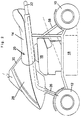
- This frame structure is not in the drawing shown, flat chassis worn, of which the The rear wheels 10 and the front wheels 12 protrude laterally.
- the overall structure is in this respect in all exemplary embodiments same as when they were trained like a motorcycle, at that of the rider on a saddle carried by the central frame 14 sits, of which the legs are arranged bent on both sides and and are carried by footrests. The legs then close between them the drive motor 16, which preferably as Internal combustion engine is designed, but also one of batteries can be powered electric motor.
- the one with a vertical shaft working motor drives a sickle knife, not shown, which revolves within a protective casing 18.
- the saddle 14 is preferably about a front, transverse axis 20 can be raised to make the engine controls easier to make it accessible.
- the opening is at 1 and 2, a handle bar 22 intended.
- the front wheels 12 are set via a steering column 26, which is surrounded by a panel 28, which in the rear part, facing the driver can carry a dashboard 30.
- a dashboard 30 On this can be arranged display devices. It can be a (not shown) gear shift lever may be provided, for example can protrude on the dashboard 30.
- a steering rod is on the steering column 26 as a control element 106 put on, as is usual with motorcycles and bicycles with operating levers adjacent to the handles, arranged for example for clutch, brake or circuit could be.
- the “motorcycle body” allows small dimensions both in the height as well as the width, so that the space requirement and that Weight of the riding lawnmower is not significantly higher, than an ordinary wheel-driven, hand-guided one Mower.
- a catch container is provided for the cut grass be preferably in the rear area of the riding lawn mower is arranged, or can be releasably attached there.
- the frame structure is in all the exemplary embodiments similar. It is characterized in that adjacent to Longitudinal axis frame elements are arranged between the Legs come to rest and carry the saddle.
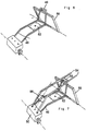
- One in particular suitable frame structure for the ride-on mower according to FIG. 1 can be seen from FIGS. 3 to 5.
- This frame structure has a horizontally lying U-frame 34 on whose side legs 36 over two converging sections 38 and a transverse central section 40 are connected.
- the ends of the legs 36 are angled 42 provided that can serve as a rear axle bearing.
- the U-frame 34 is at its bend points with the Leg ends of a vertical bracket 44 welded (Fig. 3).
- the frame structure is completed, as can be seen from FIG. 5, by two further kinked profile beams 54 which, just like the other frame parts, be designed as tubes can and start on the steering housing 50 and a kink run diagonally upwards and on the tab 48 or the profile beams 46 are welded in the area of the tab.
- profile carrier 54 Plate 56 welded with a sleeve that the steering column 26th leads.
- the drive motor 16 drives in all embodiments via a corresponding gear 104 and a clutch Rear wheels 10 on. 6 and 7, the in particular for the ride-on lawn mower according to FIG. 2 is essentially the same as the frame structure 3 to 5.
- Deviating from this embodiment is instead of Strap 44 a rectangular rear frame 58 is provided, the one Catcher attachment and an axle bearing. With this Embodiment falls that shown in Fig. 3 to 5 U-frame 34 away, resulting in an even narrower structure.
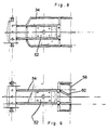
- FIGS. 8 and 9. Fig. 8 shows 3 to 5 a plan view of a frame structure, 9 shows a frame structure according to the exemplary embodiment 6 and 7. 9 leaves another at the rear discharge, i.e. on the rear frame 58, arranged guide surface 60 recognize the grass in the best way into the grass catcher can be promoted.
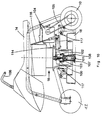
- the drive motor 16 shown only schematically 16 arranged. From the drive motor 16 stands down a vertically arranged motor output shaft 100 in front of which both the rear wheels 10 and the knife shaft 101 and thus the cutting knives are driven.
- first coupling device 102 arranged around the knife shaft 101 to connect to the engine output shaft 100.
- the desired cutting height is set using a lever 116, by the cover 18 together with the cutting knives raised or lowered via a linkage arrangement 117 becomes.
- the knife shaft 101 is formed in two parts. An upper one Part is formed by an internally toothed hollow cylinder 108, which is connected to the attenuator 103. In this cabbage cylinder is another part of the knife shaft telescopically introduced, which carries a pinion 107, which in the internal toothing of the hollow cylinder 108 engages. If the cutting blades are raised together with the cover 18 or be lowered, the part supporting the pinion 107 becomes the knife shaft axially in the internally toothed hollow cylinder 108 shifted, the positive with respect to the shaft rotation Connection remains. Like this in Fig. 10 is clearly shown is the vertical motor output shaft 100 axially aligned with the knife shaft 101.
- a first pulley 110 is arranged directly on the engine output shaft 100, i.e. above the first coupling device 102.
- a manual transmission 104 is arranged on the riding lawn mower, from which down a substantially vertical arranged shaft 113 protrudes.
- shaft 113 protrudes.
- a drive belt 114 transmits the force from the pulley 110 to the pulley 111 and thus the transmission 104 when the belt tension is increased.
- an element that is formed, for example, in the form of a pedal 115 can be, whereby another pulley 112 such is pressed against the belt 114 so that the belt tension raised enough to allow power transmission.
- the element 115 slips the belt 114 over the pulley 110.
- the just The arrangement described forms a second coupling device 109, via which the drive wheels 10 with the motor output shaft 100 can be connected.
- the power transmission from the transmission 104 to the drive wheels 10 takes place via at least one another strap 105.
Landscapes
- Life Sciences & Earth Sciences (AREA)
- Environmental Sciences (AREA)
- Harvester Elements (AREA)
Description
- Fig. 1
- zeigt in einer schematischen Seitenansicht einen erfindungsgemäß ausgebildeten Aufsitzrasenmäher;
- Fig. 2
- zeigt eine Seitenansicht eines hinsichtlich des Rahmens abgewandelten Aufsitzrasenmäher;
- Fig. 3 bis 5
- zeigen perspektivische Darstellungen des Rahmenaufbaus des Aufsitzrasenmähers gemäß Fig. 1;
- Fig. 6 und 7
- zeigen perspektivische Darstellungen des Rahmenaufbaus des Aufsitzrasenmähers gemäß Fig. 2;
- Fig. 8 und 9
- zeigen zwei schematische Draufsichten des Rahmenaufbaus eines erfindungsgemäß ausgebildeten Aufsitzrasenmähers;
- Fig. 10
- zeigt eine schematische Seitenansicht einer weiteren Ausführungsform des erfindungsgemäßen Aufsitzrasenmähers;
- Fig. 11
- zeigt eine schematische, teilweise geschnittene Draufsicht des Aufsitzrasenmähers nach Fig. 10; und
- Fig. 12
- zeigt eine Ausführungsform des Verbindungsbereiches zwischen Antriebsmotor und Schneidmesser.
- 10
- Hinterräder
- 12
- Vorderräder
- 14
- Sattel
- 16
- Antriebsmotor
- 18
- Schutzumkleidung
- 20
- Achse
- 22
- Handgriffbügel
- 26
- Lenksäule
- 28
- Verkleidung
- 30
- Armaturenbrett
- 34
- U-Rahmen
- 36
- Seitenschenkel
- 38
- Abschnitte
- 40
- Mittelabschnitt
- 42
- Abwinkelung
- 44
- Bügel
- 46
- Profilträger
- 48
- Lasche
- 50
- Lenkgehäuse
- 52
- Platte
- 54
- Profilträger
- 56
- Platte
- 58
- Heckrahmen
- 60
- Leitfläche
- 100
- Motorabtriebswelle
- 101
- Messerwelle
- 102
- erste Kupplungseinrichtung
- 103
- torsionselastisches Dämpfungsglied
- 104
- Schaltgetriebe
- 105
- Riemen
- 106
- Lenkstange
- 107
- Ritzel
- 108
- Hohlzylinder
- 109
- zweite Kupplungseinrichtung
- 110
- Riemenscheibe
- 111
- Riemenscheibe
- 112
- Riemenscheibe
- 113
- Welle
- 114
- Antriebsriemen
- 115
- Pedal
- 116
- Hebel
- 117
- Gestängeanordnung
Claims (13)
- Aufsitzrasenmäher mit einem Antriebsmotor (16) für die Schneidmesser und den Fahrantrieb, mit einer Motorabtriebswelle (100), mit einer Messerwelle (101), mit einem Sitz (14), unter dem der Antriebsmotor (16) angeordnet ist, mit einem Fahrgestell, das zwei vom Antriebsmotor (16) angetriebene Hinterräder (10) und zwei lenkbare Vorderräder (12) aufweist, zwischen denen der Mähstreifen zu liegen kommt, und mit einem Rahmenaufbau, dessen Vorderteil mit einem Lenkgehäuse (50) verbunden ist, in dem eine in dieses eintauchende Lenksäule gelagert ist,
dadurch gekennzeichnet, daß der Sitz in Form eines Sattels (14) ausgebildet ist, wobei die Beine des Fahrers zwischen sich Antriebselemente einschließen, daß der Rahmenaufbau ein zentraler Rahmenaufbau ist, an dem das Fahrgestell, eine Lenkeinrichtung und der Antrieb (16) aufgehängt sind, wobei der Sattel (14) an dem Rabmenaufbau abgestützt ist, daß die Längsachsen der Motorabtriebswelle (100) und die Messerwelle (101) axial ausgerichtet und vertikal angeordnet sind, daß die Motorabtriebswelle (100) und die Messerwelle über eine erste Kupplungseinrichtung (102) und ein torsionselastisches Dämpfungsglied verbindbar sind, daß das torsionselastische Dämpfungsglied zwischen der ersten Kupplungseinrichtung (102) und der Messerwelle (101) angeordnet ist, wobei das Abtriebsglied der ersten Kupplungseinrichtung (102) im äußeren Umfangsbereich des Dämpfungsgliedes eingreift, während die Messerwelle im Innenbereich des Dämpfungsgliedes derart eingreift, daß sowohl messerseitige als auch motorseitige Kraftstöße bzw. Impulse elastisch ausgeglichen werden, daß die beiden Hinterräder (10) über eine zweite Kupplungseinrichtung (109), ein Getriebe (104) und/oder eine Riemen- bzw. Kettenanordnung (105) mit der Motorabtriebswelle (100) verbindbar sind, und daß die Lenksäule mit einer Lenkstange (106) verbunden ist, die Bedienelemente trägt. - Aufsitzrasenmäher nach Anspruch 1,
dadurch gekennzeichnet, daß die Messerwelle eine Schnitthöhenverstellung einschließt, die durch die axiale Verschiebbarkeit der Messerwelle (101) gegenüber der Motorabtriebswelle (100) gebildet ist, wobei die Messerswelle (101) ein Ritzel (107) trägt, das mit einem innenverzahnten Hohlzylinder (108) in Eingriff steht, der mit dem torsionselastischen Dämpfungsglied (103) verbunden ist. - Aufsitzrasenmäher nach Anspruch 1 oder 2,
dadurch gekennzeichnet, daß die zweite Kupplungseinrichtung (109) durch einen Riemen (114), der über eine erste an der Motorabtriebswelle (100) befestigte Riemenscheibe (110) und eine zweite an einer mit dem Getriebe in Verbindung stehenden und parallel zur Motorabtriebswelle (100) angeordneten Welle (113) befestigte Riemenscheibe (111) läuft gebildet ist, wobei die kraftschlüssige Verbindung der beiden Riemescheiben (110,111) durch die Betätigung eines Elementes (115) erzeugt wird, über das der Riemen (114) gespannt wird, während dieser über die erste Riemenscheibe (110) rutscht, wenn das Element (115) nicht betätigt ist. - Aufsitzrasenmäher nach einem der vorhergehenden Ansprüche,
dadurch gekennzeichnet, daß auf beiden Seiten des Aufbaus Fußrasten oder Fußplatten vorgesehen sind, die zumindest mit dem Element (115) kombiniert sind, wenn dieses vorhanden ist. - Aufsitzrasenmäher nach einem der vorhergehenden Ansprüche,
dadurch gekennzeichnet, daß der Rahmenaufbau und/oder der Antriebsmotor (16) durch eine Karosserie verkleidet ist. - Aufsitzrasenmäher nach einem der vorhergehenden Ansprüche,
dadurch gekennzeichnet, daß der Vorderteil mit der Lenkanordnung eine Verkleidung (28) mit einem dem Fahrer zugewandten Armaturenbrett (30) trägt. - Aufsitzrasenmäher nach einem der vorhergehenden Ansprüche,
dadurch gekennzeichnet, daß der Sattel (14) als Sitz mit oder ohne Lehne ausgebildet ist. - Aufsitzrasenmäher nach einem der vorhergehenden Ansprüche,
dadurch gekennzeichnet, daß der Sattel (14) um eine Achse (20) nach oben aufklappbar ist. - Aufsitzrasenmäher nach einem der vorhergehenden Ansprüche,
dadurch gekennzeichnet, daß der Rahmenaufbau zwei abgeknickte Profilträgerpaare (46,54) aufweist, die im geringen Abstand zueinander benachbart zur Längsachse angeordnet und miteinander und mit Versteifungsmitteln (52, 56, 48) verschweißt sind. - Aufsitzrasenmäher nach Anspruch 9,
dadurch gekennzeichnet, daß im hintere Abschnitt der abgeknickten Profilträgerpaare (46,54) ein quer verlaufender, vertikal stehender Bügel (44) angeschweißt ist. - Aufsitzrasenmäher nach Anspruch 9,
dadurch gekennzeichnet, daß mit den Profilträgerpaaren (46,54) ein Heckrahmen (58) verschweißt ist. - Aufsitzrasenmäher nach den Ansprüchen 9 und 10,
dadurch gekennzeichnet, daß an den geknickten Profilträgerpaaren (46,54) ein horizontaler U-Rahmen angeschweißt ist. - Aufsitzrasenmäher nach Anspruch 9,
dadurch gekennzeichnet, daß die Profilträgerpaare (46,54) im Vorderteil mit dem Lenkgehäuse (50) verbunden sind.
Applications Claiming Priority (3)
| Application Number | Priority Date | Filing Date | Title |
|---|---|---|---|
| DE19538230 | 1995-10-13 | ||
| DE19538230 | 1995-10-13 | ||
| PCT/EP1996/004410 WO1997013400A1 (de) | 1995-10-13 | 1996-10-10 | Aufsitzrasenmäher |
Publications (2)
| Publication Number | Publication Date |
|---|---|
| EP0854672A1 EP0854672A1 (de) | 1998-07-29 |
| EP0854672B1 true EP0854672B1 (de) | 1999-08-25 |
Family
ID=7774820
Family Applications (1)
| Application Number | Title | Priority Date | Filing Date |
|---|---|---|---|
| EP96934623A Expired - Lifetime EP0854672B1 (de) | 1995-10-13 | 1996-10-10 | Aufsitzrasenmäher |
Country Status (4)
| Country | Link |
|---|---|
| EP (1) | EP0854672B1 (de) |
| AT (1) | ATE183611T1 (de) |
| DE (1) | DE59602900D1 (de) |
| WO (1) | WO1997013400A1 (de) |
Cited By (1)
| Publication number | Priority date | Publication date | Assignee | Title |
|---|---|---|---|---|
| DE102008022418A1 (de) * | 2008-05-07 | 2009-11-12 | GM Global Technology Operations, Inc., Detroit | Sitzeinrichtung |
Families Citing this family (2)
| Publication number | Priority date | Publication date | Assignee | Title |
|---|---|---|---|---|
| FR2782599B1 (fr) * | 1998-08-28 | 2000-11-10 | Granja | Tondeuse a gazon autoportee legere, procede de fabrication et kit de mise en oeuvre |
| WO2010117363A1 (en) * | 2009-04-09 | 2010-10-14 | Michelin Recherche Et Technique, S.A. | Tire metallic cable anomaly detection method and apparatus |
Family Cites Families (8)
| Publication number | Priority date | Publication date | Assignee | Title |
|---|---|---|---|---|
| US2551817A (en) * | 1945-12-03 | 1951-05-08 | Homer L Taylor | Rotating cutting-disk type mower |
| FR1228919A (fr) * | 1959-03-16 | 1960-09-02 | Tondeuse à gazon | |
| US3839919A (en) * | 1971-04-08 | 1974-10-08 | Ariens Co | Riding mower |
| US4807904A (en) * | 1987-05-07 | 1989-02-28 | Simplicity Manufacturing, Inc. | Riding mower chassis having improved rear portion |
| JPH0787823A (ja) * | 1993-09-27 | 1995-04-04 | Kubota Corp | モーア |
| DE4413332C2 (de) * | 1994-04-18 | 2002-06-06 | Etesia S A R L Wissembourg | Aufsitz-Rasenmäher |
| US5433066A (en) * | 1994-06-10 | 1995-07-18 | Ferris Industries, Inc. | Vehicle frame and cutter assembly lifting mechanism for riding lawn mower |
| DE29521119U1 (de) * | 1995-08-10 | 1996-08-29 | WOLF-Geräte GmbH Vertriebsges. KG, 57518 Betzdorf | Aufsitz-Rasenmäher |
-
1996
- 1996-10-10 AT AT96934623T patent/ATE183611T1/de not_active IP Right Cessation
- 1996-10-10 EP EP96934623A patent/EP0854672B1/de not_active Expired - Lifetime
- 1996-10-10 WO PCT/EP1996/004410 patent/WO1997013400A1/de not_active Ceased
- 1996-10-10 DE DE59602900T patent/DE59602900D1/de not_active Expired - Fee Related
Cited By (1)
| Publication number | Priority date | Publication date | Assignee | Title |
|---|---|---|---|---|
| DE102008022418A1 (de) * | 2008-05-07 | 2009-11-12 | GM Global Technology Operations, Inc., Detroit | Sitzeinrichtung |
Also Published As
| Publication number | Publication date |
|---|---|
| WO1997013400A1 (de) | 1997-04-17 |
| DE59602900D1 (de) | 1999-09-30 |
| ATE183611T1 (de) | 1999-09-15 |
| EP0854672A1 (de) | 1998-07-29 |
Similar Documents
| Publication | Publication Date | Title |
|---|---|---|
| DE3530557C2 (de) | ||
| DE69710142T2 (de) | Elektrischer Rasenmäher | |
| EP1295521B1 (de) | Arbeitsgerät und Gerät zur Rasen-,Garten- und Grundstückspflege | |
| DE3855589T2 (de) | Rasenmäher, dessen Benutzer hinterher läuft | |
| DE69813386T2 (de) | Rucksackarbeitsmaschine | |
| DE3532830A1 (de) | Motorrasenmaeher | |
| DE69708901T2 (de) | Hintere aufhängung für selbstfahrenden mäher | |
| DE602004004176T2 (de) | Arbeitsgerät | |
| DE3047643C2 (de) | An der Frontseite eines Fahrzeuges ankoppelbares, freischneidendes Scheibenmähwerk | |
| WO1997013400A1 (de) | Aufsitzrasenmäher | |
| EP1415525A1 (de) | Trenneinrichtung | |
| EP0678235B1 (de) | Aufsitz-Rasenmäher | |
| DE2820668C2 (de) | Traktor | |
| DE3332192A1 (de) | Selbstfahrende maehmaschine fuer gras, getreide und dergleichen | |
| DE835260C (de) | Anordnung bei Einachsschleppern | |
| DE2757844A1 (de) | Tragbares gasmotorgetriebenes schneidwerkzeug | |
| DE29521119U1 (de) | Aufsitz-Rasenmäher | |
| DE19934636C2 (de) | Rasenmäher | |
| DE69923693T2 (de) | Mäher mit heckseitigem grassauswurf | |
| DE69418738T2 (de) | Untersetzungsgetriebe für selbstangetriebene Rasenmäher | |
| DE900150C (de) | Mit zwei angetriebenen Fahrraedern versehene landwirtschaftliche Kleinmaschine | |
| DE3336533C2 (de) | Landwirtschaftliches motorbetriebenes Gerät | |
| DE102019112930B4 (de) | Antriebsanordnung für ein Zuggerät sowie Zuggerät für eine fahrbare Sitzeinheit | |
| DE2414568A1 (de) | Rasenmaeher | |
| DE2715642A1 (de) | Selbstfahrende heuerntemaschine |
Legal Events
| Date | Code | Title | Description |
|---|---|---|---|
| PUAI | Public reference made under article 153(3) epc to a published international application that has entered the european phase |
Free format text: ORIGINAL CODE: 0009012 |
|
| 17P | Request for examination filed |
Effective date: 19980407 |
|
| AK | Designated contracting states |
Kind code of ref document: A1 Designated state(s): AT BE CH DE ES FR GB IT LI NL SE |
|
| GRAG | Despatch of communication of intention to grant |
Free format text: ORIGINAL CODE: EPIDOS AGRA |
|
| GRAG | Despatch of communication of intention to grant |
Free format text: ORIGINAL CODE: EPIDOS AGRA |
|
| GRAH | Despatch of communication of intention to grant a patent |
Free format text: ORIGINAL CODE: EPIDOS IGRA |
|
| 17Q | First examination report despatched |
Effective date: 19990201 |
|
| GRAH | Despatch of communication of intention to grant a patent |
Free format text: ORIGINAL CODE: EPIDOS IGRA |
|
| GRAA | (expected) grant |
Free format text: ORIGINAL CODE: 0009210 |
|
| ITF | It: translation for a ep patent filed | ||
| GBT | Gb: translation of ep patent filed (gb section 77(6)(a)/1977) |
Effective date: 19990726 |
|
| AK | Designated contracting states |
Kind code of ref document: B1 Designated state(s): AT BE CH DE ES FR GB IT LI NL SE |
|
| PG25 | Lapsed in a contracting state [announced via postgrant information from national office to epo] |
Ref country code: ES Free format text: THE PATENT HAS BEEN ANNULLED BY A DECISION OF A NATIONAL AUTHORITY Effective date: 19990825 |
|
| REF | Corresponds to: |
Ref document number: 183611 Country of ref document: AT Date of ref document: 19990915 Kind code of ref document: T |
|
| REG | Reference to a national code |
Ref country code: CH Ref legal event code: EP |
|
| GBT | Gb: translation of ep patent filed (gb section 77(6)(a)/1977) |
Effective date: 19990805 |
|
| ET | Fr: translation filed | ||
| GBT | Gb: translation of ep patent filed (gb section 77(6)(a)/1977) |
Effective date: 19990827 |
|
| REF | Corresponds to: |
Ref document number: 59602900 Country of ref document: DE Date of ref document: 19990930 |
|
| PLBE | No opposition filed within time limit |
Free format text: ORIGINAL CODE: 0009261 |
|
| STAA | Information on the status of an ep patent application or granted ep patent |
Free format text: STATUS: NO OPPOSITION FILED WITHIN TIME LIMIT |
|
| 26N | No opposition filed | ||
| PG25 | Lapsed in a contracting state [announced via postgrant information from national office to epo] |
Ref country code: LI Free format text: LAPSE BECAUSE OF NON-PAYMENT OF DUE FEES Effective date: 20001031 Ref country code: CH Free format text: LAPSE BECAUSE OF NON-PAYMENT OF DUE FEES Effective date: 20001031 |
|
| REG | Reference to a national code |
Ref country code: CH Ref legal event code: PL |
|
| PGFP | Annual fee paid to national office [announced via postgrant information from national office to epo] |
Ref country code: NL Payment date: 20010830 Year of fee payment: 6 |
|
| PGFP | Annual fee paid to national office [announced via postgrant information from national office to epo] |
Ref country code: DE Payment date: 20010907 Year of fee payment: 6 Ref country code: AT Payment date: 20010907 Year of fee payment: 6 |
|
| PGFP | Annual fee paid to national office [announced via postgrant information from national office to epo] |
Ref country code: SE Payment date: 20010910 Year of fee payment: 6 Ref country code: FR Payment date: 20010910 Year of fee payment: 6 |
|
| PGFP | Annual fee paid to national office [announced via postgrant information from national office to epo] |
Ref country code: GB Payment date: 20010928 Year of fee payment: 6 |
|
| PGFP | Annual fee paid to national office [announced via postgrant information from national office to epo] |
Ref country code: BE Payment date: 20011001 Year of fee payment: 6 |
|
| REG | Reference to a national code |
Ref country code: GB Ref legal event code: IF02 |
|
| PG25 | Lapsed in a contracting state [announced via postgrant information from national office to epo] |
Ref country code: GB Free format text: LAPSE BECAUSE OF NON-PAYMENT OF DUE FEES Effective date: 20021010 Ref country code: AT Free format text: LAPSE BECAUSE OF NON-PAYMENT OF DUE FEES Effective date: 20021010 |
|
| PG25 | Lapsed in a contracting state [announced via postgrant information from national office to epo] |
Ref country code: SE Free format text: LAPSE BECAUSE OF NON-PAYMENT OF DUE FEES Effective date: 20021011 |
|
| PG25 | Lapsed in a contracting state [announced via postgrant information from national office to epo] |
Ref country code: BE Free format text: LAPSE BECAUSE OF NON-PAYMENT OF DUE FEES Effective date: 20021031 |
|
| BERE | Be: lapsed |
Owner name: *WOLFGERATE G.M.B.H. VERTRIEBSGESELLSCHAFT K.G. Effective date: 20021031 |
|
| PG25 | Lapsed in a contracting state [announced via postgrant information from national office to epo] |
Ref country code: NL Free format text: LAPSE BECAUSE OF NON-PAYMENT OF DUE FEES Effective date: 20030501 Ref country code: DE Free format text: LAPSE BECAUSE OF NON-PAYMENT OF DUE FEES Effective date: 20030501 |
|
| GBPC | Gb: european patent ceased through non-payment of renewal fee |
Effective date: 20021010 |
|
| EUG | Se: european patent has lapsed | ||
| PG25 | Lapsed in a contracting state [announced via postgrant information from national office to epo] |
Ref country code: FR Free format text: LAPSE BECAUSE OF NON-PAYMENT OF DUE FEES Effective date: 20030630 |
|
| NLV4 | Nl: lapsed or anulled due to non-payment of the annual fee |
Effective date: 20030501 |
|
| REG | Reference to a national code |
Ref country code: FR Ref legal event code: ST |
|
| PG25 | Lapsed in a contracting state [announced via postgrant information from national office to epo] |
Ref country code: IT Free format text: LAPSE BECAUSE OF NON-PAYMENT OF DUE FEES;WARNING: LAPSES OF ITALIAN PATENTS WITH EFFECTIVE DATE BEFORE 2007 MAY HAVE OCCURRED AT ANY TIME BEFORE 2007. THE CORRECT EFFECTIVE DATE MAY BE DIFFERENT FROM THE ONE RECORDED. Effective date: 20051010 |