EP0854819B2 - Systeme permettant de fixer de maniere amovible un recipient sur une bicyclette - Google Patents
Systeme permettant de fixer de maniere amovible un recipient sur une bicyclette Download PDFInfo
- Publication number
- EP0854819B2 EP0854819B2 EP96931036A EP96931036A EP0854819B2 EP 0854819 B2 EP0854819 B2 EP 0854819B2 EP 96931036 A EP96931036 A EP 96931036A EP 96931036 A EP96931036 A EP 96931036A EP 0854819 B2 EP0854819 B2 EP 0854819B2
- Authority
- EP
- European Patent Office
- Prior art keywords
- handlebar
- carrier member
- holder according
- container
- piece
- Prior art date
- Legal status (The legal status is an assumption and is not a legal conclusion. Google has not performed a legal analysis and makes no representation as to the accuracy of the status listed.)
- Expired - Lifetime
Links
- 230000008093 supporting effect Effects 0.000 claims description 7
- 230000008878 coupling Effects 0.000 claims description 6
- 238000010168 coupling process Methods 0.000 claims description 6
- 238000005859 coupling reaction Methods 0.000 claims description 6
- 210000000078 claw Anatomy 0.000 claims description 4
- 238000006073 displacement reaction Methods 0.000 claims description 3
- 238000010276 construction Methods 0.000 abstract description 2
- 210000002414 leg Anatomy 0.000 description 8
- 230000007246 mechanism Effects 0.000 description 3
- 230000007704 transition Effects 0.000 description 3
- 230000000694 effects Effects 0.000 description 2
- 230000008859 change Effects 0.000 description 1
- 230000001427 coherent effect Effects 0.000 description 1
- 230000005484 gravity Effects 0.000 description 1
- 238000000034 method Methods 0.000 description 1
- 238000000465 moulding Methods 0.000 description 1
- 230000010355 oscillation Effects 0.000 description 1
- 235000020004 porter Nutrition 0.000 description 1
- 230000008569 process Effects 0.000 description 1
- 239000007787 solid Substances 0.000 description 1
- 230000008719 thickening Effects 0.000 description 1
- 210000000689 upper leg Anatomy 0.000 description 1
Images




Classifications
-
- B—PERFORMING OPERATIONS; TRANSPORTING
- B62—LAND VEHICLES FOR TRAVELLING OTHERWISE THAN ON RAILS
- B62J—CYCLE SADDLES OR SEATS; AUXILIARY DEVICES OR ACCESSORIES SPECIALLY ADAPTED TO CYCLES AND NOT OTHERWISE PROVIDED FOR, e.g. ARTICLE CARRIERS OR CYCLE PROTECTORS
- B62J9/00—Containers specially adapted for cycles, e.g. panniers or saddle bags
- B62J9/20—Containers specially adapted for cycles, e.g. panniers or saddle bags attached to the cycle as accessories
- B62J9/21—Containers specially adapted for cycles, e.g. panniers or saddle bags attached to the cycle as accessories above or alongside the front wheel, e.g. on the handlebars
-
- B—PERFORMING OPERATIONS; TRANSPORTING
- B62—LAND VEHICLES FOR TRAVELLING OTHERWISE THAN ON RAILS
- B62J—CYCLE SADDLES OR SEATS; AUXILIARY DEVICES OR ACCESSORIES SPECIALLY ADAPTED TO CYCLES AND NOT OTHERWISE PROVIDED FOR, e.g. ARTICLE CARRIERS OR CYCLE PROTECTORS
- B62J9/00—Containers specially adapted for cycles, e.g. panniers or saddle bags
- B62J9/20—Containers specially adapted for cycles, e.g. panniers or saddle bags attached to the cycle as accessories
- B62J9/27—Containers specially adapted for cycles, e.g. panniers or saddle bags attached to the cycle as accessories characterised by mounting arrangements, e.g. quick release arrangements
-
- B—PERFORMING OPERATIONS; TRANSPORTING
- B62—LAND VEHICLES FOR TRAVELLING OTHERWISE THAN ON RAILS
- B62J—CYCLE SADDLES OR SEATS; AUXILIARY DEVICES OR ACCESSORIES SPECIALLY ADAPTED TO CYCLES AND NOT OTHERWISE PROVIDED FOR, e.g. ARTICLE CARRIERS OR CYCLE PROTECTORS
- B62J9/00—Containers specially adapted for cycles, e.g. panniers or saddle bags
- B62J9/20—Containers specially adapted for cycles, e.g. panniers or saddle bags attached to the cycle as accessories
- B62J9/23—Containers specially adapted for cycles, e.g. panniers or saddle bags attached to the cycle as accessories above or alongside the rear wheel
Definitions
- the invention relates to a holder for releasably attaching a container to a Bicycle with one on the handlebar on the right and left adjustable from a handlebar stem using clamps definable and on the stem by means of a Strap supportable piece on which the clamps can be used with their free ends and tensioned are, with a rigidly connected to the bracket Bow piece, which has external teeth, by means of the bracket in the loosened state of the clamps an internal toothing adjustable relative to the carrier piece and cannot be adjusted when the clamps are tightened is fixed, and with one on the Carrier piece releasably attachable to the container attached or attachable holding piece.
- a holder for containers on a bicycle is also specified in DE 39 27 086 A1.
- bracket is on the handlebar or a carrier piece is attached to the luggage rack of the bicycle, on which a box-like container or a pannier be coupled by means of a holding piece can.
- the holding piece has an elongated Hook profile with a circular thickening on the Hook end to form an axis of rotation.
- Below a locking bracket is provided for the hook profile, that when swiveling the box into one Locking shaft engages and is locked in it.
- the sides of the box take over the lateral Give the locking bracket in the closing shaft.
- the bolt is actuated by a Handle arranged on top of the carrier piece.
- For the lateral attachment of the luggage bag on the A snap hook is provided for the luggage rack an upper longitudinal bar of the luggage carrier immediately overlaps, the hook mechanism consisting of several separate parts is assembled.
- DE 40 08 211 A1 is on the handlebar attachable support piece specified with one that can be brought into contact with the stem Support section is engaged.
- the definition the container on the carrier piece is similar as in the aforementioned publication.
- DE 23 099 A1 shows a holder for a Container in the form of a wire basket on a luggage rack.
- the one inserted from the inside of the wire basket Holding piece reaches through with a screw attachment the wire mesh, and in the approach is a hook element perpendicular to the support surface of the holding piece led recorded that by means of a screw the luggage rack is clampable. hereby is the effort involved in attaching and detaching of the wire basket relatively high.
- the invention has for its object a To provide a holder of the type mentioned at the outset, which is simple in structure and operation and one reliable definition of the container guaranteed.
- connection of the clamps to the support piece is simple and stable in that the carrier piece on its facing away from the holding piece Back of the four legs to connect the clamps has, in the four legs of two on the Bicycle handlebar arranged clamps are, and that the support piece and the clamps by means by screwing the carrier piece in Screw channels of the legs of inserted screws can be fixed on the handlebar together with the bracket are.
- the training can also be such that the clamps at least over an axial inner or outer partial area have an internal toothing that the elbows over a radially spaced crossbar are interconnected and that the traverse with the support piece aligned in the desired position on the stem or stem against a torque generated by the container can be struck.
- a stable fixation on the handlebar is further supported by the fact that the handlebar facing inner surface of the clamps and / or the arc pieces are designed to be non-slip.
- hook elements and the hook receptacles and the facing sides of the Carrier piece and the holding piece formed in such a way are that for coupling those facing each other Pages in plant can be brought together and then the definition by a shifting movement under friction, force and / or positive locking he follows.
- the hook elements and the hook mounts are simply on the sides facing each other the carrier piece and the holding piece can be formed, by adding the appropriate items for example are integrally formed on the respective elements.
- the coupling of the container to the bike happens simply because the holding piece on the Carrier piece is inserted.
- the carrier piece and that Holding piece are in the attached state with their facing sides firmly against each other, so that also at Vibrations and oscillations the carrier piece and the holding piece does not move relative to each other and a safe, vibration-free coupling between the two parts is guaranteed.
- the measures open up the possibility of different Containers such as Bags, wicker basket, wire basket, Plastic boxes and the like with the same adapter elements at different places on the bike to install.
- the holding piece is plate-like is trained and that the hook recordings through at least one recess and provided thereon Undercuts are formed and that the hook elements formed on the carrier piece as a projection are that engage in the recess (s), or that conversely the hook receptacles on the carrier piece through at least one recess and provided thereon Undercuts are formed and that the hook elements formed on the holding piece as a projection are that engage in the recess (es), it results the possibility of the holding piece on a suitable Wall of the container simple and permanent to be attached without it being disturbing. The container can then be easily attached to the bike at any time and be removed from it. As a result of that the projection with the hook elements in the recesses engages, it is achieved that the holding piece is simple and positioned exactly on the carrier plate Moving can be set and laterally immovable is stored.
- the detent spring protrudes over an edge of the support piece and from Hand can be operated to release the locking connection.
- bracket results from the fact that the carrier piece and Holding piece each as a fitting with the hook elements or the hook receptacles and possibly the locking element are trained. You don't have to do several Individual parts for the construction of the carrier piece or the holding piece be put together. Good functionality is given in the long run.
- An alternative support for the support piece is that the two clamps are each radial have protruding connector, in the An adjustable crossbeam or a fixed end area Traverse with an adjusting screw for support the stem or the stem is.
- a simple anti-theft device for one the container attached to the bicycle is replaced by the Measure achieved that a lock holder on the holding piece can be fixed by means of screws or locking pins and that a lock inserted in the lock holder with a container attached to the bicycle with a Locking pin in a locking opening lockable engages.
- a container can always be easily on one Carrier attached or detached be provided if it is provided that the carrier piece by means of on the side facing away from the holding piece attachable fastening tabs on the top the luggage rack is clampable.
- the holding piece can be used on luggage racks of different dimensions and designs just because of it be that the mounting tabs in or parallel to the level of the carrier piece in guide grooves or Guide slots adjustable and lockable are.
- a stable fixation even on thicker poles the porter is favored in that the fastening tabs at one end area a holding time for clamping onto the luggage rack linkage and one at its other end Support section with a guide part and a between the two end portions arranged projection to accommodate a screw.
- the respective mounting bracket can be easily and be clearly guided to the desired location, the holding claw largely and the linkage clutched tightly.
- FIG. 1 shows a holder 1 with a a handlebar 2 attached support piece 11 and a holding piece attached to the outside of a container 4 12.
- the carrier piece 11 is by means of two clamps 10 attached to the handlebar 2 and against one of the container 4 generated torque by means of a Bracket 15 on the underside of a stem 3 supported.
- the bracket on the handlebar shaft could be similar be supported.
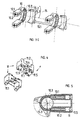
- FIG. 2 is the attached state of the Container 4 shown. That with an inner plate 13th attached to a wall of the container 4 holding piece 12 is by means of pocket-like hook receptacles 12.1 in adapted, also pocket-like Hook elements 11.1 of the carrier piece 11 hooked in, the hook elements in recesses 12.5 of Stick piece 12 protrude and with their outside support on the bottom of the recess 12.5. With the hook elements 11.1 join the inside the inside of the hook mounts 12.1 in contact. The hook elements 11.1 are frictionally engaged in the Hook recordings 12.1 fitted so that the Container not subject to vibrations and vibrations releases from the support piece 11, especially since gravity counteracts loosening.
- Container 4 For hanging it up Container 4 with the holding piece 12 first to the carrier piece 11 set flat and then in the hanging direction r pushed down.
- the inner plate 13 is with screws in screw domes 12.2 of the holding piece 12 set.
- the carrier piece 11 is on legs 10.1 of the clamps 10, which are shown in FIGS. 3A and 3B are shown, attached and screwed to it, so that the clamps 10 with the support piece 11 firmly on the Handlebar 2 are attached.
- Fig. 3A shows that on the handlebar 2 and the Container 4 to be attached holder 1 in an exploded view.
- a wall of the container 4 becomes solid added while the carrier piece 11 with the Clamps 10 is set on the handlebar 2, wherein the legs 10.1 in the leg receptacles 11.2 inserted and the elbows 15.3 between the Clamps 10 and the handlebar 2 clamped adjustable are.
- the arch pieces 15.3 have external teeth 15.2 on the 10.3 with an internal toothing Collars 10 cooperate across their entire width. Which extend over the entire width of the clamps 10 extending external toothing 15.2 is on both sides of Confined sections 15.4, so that there is a clear Fixing the bracket 15 results.
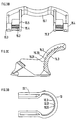
- 3B to 3D show enlarged representations the bracket 15 and the clamp 10.
- the internal teeth 10.3 of the clamp 10 and the external teeth 15.2 of the bracket 15 sawtooth-shaped Tooth flanks, steep tooth flanks 10.31 or 15.21 a rotation of the support piece 11 against the Support of the bracket 15 on the handlebar stem 3 in counteract the established state.
- steep tooth flanks 15.21 and 10.31 lie flat Tooth flanks 15.20 of the bracket 15 and 10.30 of the Clamp 10.
- the external toothing 15.2 is on both sides of the collar sections 15.4 limited so that the clamp 10 is also clearly defined axially immovable.
- Both fret sections are web-like Transition sections 15.5 in one piece with the cross member 15.1 connected, the clamp 10 between the Transition sections is passed and a stable fixing of the bracket 15 relative to the carrier piece 11 on the one hand and opposite the handlebar 2 and the stem 3 is achieved on the other hand.
- the Clamps 10 about half of their axial extent the internal teeth 10.3, in which the external teeth 15.2 of the bow piece 15.3 of the bracket 15 can be used.
- Screw receptacles 11.5 of the carrier piece 11 introduced and in screw channels 10.2 of the leg 10.1 protruding screws are the two elbows 15.3 between the inside of the clamps 10 and the Clamped outside of the handlebar 2.
- the arches 15.3 in Circumferential direction in the internal teeth 10.3 of the clamps 10 are adjusted until the traverse 15.1, which the connects two pieces of arch 15.3 together the stem 3 or the stem is applied.
- two are in the direction of hanging r spaced hook parts 11.1 a respective projection by undercut formed.
- the protrusions can be attached Condition of the container 4, for example, from the side the corresponding limits of the recess 12.5 so that the seat piece is clearly seated 12 ensured on the support piece 11 and a lateral displacement is excluded. Also will a lateral shift through the lateral boundaries the bag-like hook elements 11.1 prevented.
- the locking finger is formed, which is at its free end region in a notch for easy hanging of the holding piece 12 runs out and then has a slightly beveled locking heel, so that the holding piece 12 without tools from the Locking can be released.
- the Protruding spring outwards at an edge area, to release the locking connection by hand.
- Conceivable is also a special actuator for Loosen the snap connection.
- a key-shaped Locking opening 11.4 with a Locking slot introduced into which a locking pin one connectable with the holding piece 12 Lock to prevent theft Container 4 can interlock.
- An element with the locking opening 11.4 can be in one piece molded or used separately.
- Fig. 5 is the cross section of the Legs 10.1 of the clamp 10 attached carrier piece 11 and the bracket 15 with the cross member 15.1 in two different angular positions offset on the circumference shown.
- the external teeth take effect 15.2 of the bow piece 15.3 each in the Internal teeth of the clamps 10 a.
- the fastening screws are through the screw mounts 11.5 of the carrier piece 11 in the screw channels 10.2 for fixing the support piece 11 to the handlebar 2 introduced and tightened in it.
- 6A shows a perspective view the inner plate 13, which is diagonal at its corner areas aligned screw bushings 13.1 in Has the shape of elongated holes.
- led screws are in the Screw domes 12.2 of the holding piece 12 through the wall or through a mesh or a grid of the container 4 screwed in to the holding piece 12 stably to define the container 4.
- 6B are in the left Representation of the screw domes 12.2 with different Screw recordings recognizable, so that Screws can be used in different positions if, e.g. Lattice bars of a carrier basket require this.
- the corresponding The front is in the right representation of the Fig.
- This right representation also shows a locking receptacle 12.4, in which that shown in Fig. 4 Locking element 11.3 in the attached state of the Container 4 or the fully inserted Holding piece 12 engages.
- This illustration also shows also the adjustment of the cutouts 12.5 to the Cross-sectional contour of the projections of the carrier piece 11 with the four hook elements 11.1.
- 6B is also in the right representation a shot with openings 12.3 shown in the Locking pin 14.2 of a lock holder 14 according to FIG. 7 intervene to a snap connection between the Highlight lock holder 14 and the holding piece 12.
- the lock holder 14 is perspective in Fig. 8 shown.
- One in a lock receptacle 14.1 Lock holder 14 inserted lock engages in the 4 described locking opening 11.4 and can be turned by turning one Key are set so that the holding piece 12th with the container 4 theft-proof on the carrier piece 11 is attached.
- the lock holder 14 can on the Holding piece 12 also be integrally formed. It is also conceivable that the lock holder on the support piece 11 and the Locking opening provided on the holding piece 12 are.
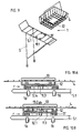
- Fig. 9 shows schematically one on one Carrier 5 mountable bracket 1 with a carrier piece 11 'and a holding piece which can be coupled thereto 12.
- a carrier piece 11 ' is on the top of the support piece 11 ' four hook elements 11.1 are provided while on the Bottom of the holding piece 12 corresponding to four Hook recordings 12.1 are arranged accordingly trained the above statements could be.
- the hook elements also on the holding piece 12 and the hook receptacles be arranged on the carrier piece 11 '; like it too for those related to handlebar mounting bracket 1 described applies.
- a container 4 is in the present case a basket made of a wire mesh is shown, attached to the bottom side of the holding piece 12 is.
- the carrier piece 11 ' is on a linkage 5.1 of the luggage rack 5 set.
- FIGS 10A and 10B show two different ones Cross sections that make up the coupling of the holding piece 12 on the carrier piece 11 'can be seen.
- the holding piece 12 is flat on the Carrier piece 11 'placed before its suspended state. This is molded onto the carrier piece 11 ' Locking element 11.3 down against Spring force deflected.
- the hook elements 11.1 and the snap-in receptacles 12.1 in a coherent connection with one another, and the locking element engages with its locking heel into the locking receptacle 12.4 of the holding piece 12 on.
- the holding piece 12 is made of the carrier piece 11 'because of a slight slope of the locking heel without tools from the support piece 11 ' pushed out.
- To secure the connected Condition of the container 4 can be a fastening screw 13.2 through the inner plate 13, the wall of the container 4 and the holding piece 12 through in a receptacle of the support piece 11 'screwed become.
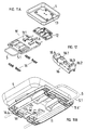
- the bracket 11A and 11B show the bracket 11 ' to attach to a luggage rack 5 and one box-like container 4 in perspective once in an exploded view and secondly from below.
- the holding piece 12 and the inner plate 13 are the same trained, as with the handlebar bracket.
- the Carrier piece 11 ' is a relatively large, plate-like Support formed, but with the holding section is matched to the holding piece 12. The large edition gives a good hold for the container 4. On this is a versatile one with a few simple parts Attachment option offered.
- FIGS. 11A and 11B and also from 10A and 10B can still be seen, that is Carrier piece 11 'on the longitudinal linkage 5.1 of the Luggage carrier 5 fixed by means of mounting tabs 16.
- a fastening tab is shown in FIG. 12 shown.
- a holding claw 16.4 is integrally formed on the end region at the opposite end Support section 16.2 integrally formed with a guide part 16.3 is.
- a projection 16.1 is formed between the holding claw 16.4 and the support section 16.2 in which a screw for clamping the holding piece 12 is added to the longitudinal linkage 5.1.
- the Guide part 16.3 allows a simple shift in a matched guide 11.6 'for example in the form of a slot or groove while the support section 16.2 following the Guide part 16.3 forms a shoulder, with which he to the Flanks of the guide is supported.
- the lead 16. 1 and the support section 16.2 is reached, that even with thicker rods of the luggage rack 5 always an extensive grip on the boom is obtained.
- the holding piece 12 is always sure set.
- the holding piece 12 also on suitable cross struts of the luggage rack 5 can be set.
- FIG. 13A and 13B show further exemplary embodiments for the clamps 10 and the connected Bracket 15.
- the two are Clamps 10 each have a radially projecting connector 10.4 in one piece with a fixed crossmember 17 connected through the center of an adjusting screw 17.1 to support on the stem 3 or the stem is turned.
- 13B is also on radially projecting connectors 10.4 one in different holes 10.5 adjustable adjustable Traverse 18 provided.
- the bracket 1 described can in particular because of the one-piece support piece 11, 11 'and the matching holding piece 12 simple z. B. made of plastic. You can the hook elements 11.1, the hook receptacles 12.1, the locking element 11.3 and the locking receptacle 12.4 be integrally formed without difficulty.
- the holding piece 12 can be used for both Luggage rack assembly as well as the handlebar assembly or another suitable assembly, such as e.g. on the side of a luggage rack or a suitable one Location of the bicycle frame, always the same training be and on a suitable wall of the Container.
Landscapes
- Engineering & Computer Science (AREA)
- Mechanical Engineering (AREA)
- Clamps And Clips (AREA)
- Steering Devices For Bicycles And Motorcycles (AREA)
Claims (17)
- Système de fixation permettant de fixer de manière amovible un récipient (4) sur une bicyclette, le système de fixation comportant une pièce de support (11) qui, au moyen de colliers de serrage (10), peut être fixée de manière réglable au guidon (2), à gauche et à droite d'une potence de guidon (3), cette pièce de support pouvant s'appuyer sur la potence de guidon (3) par l'intermédiaire d'un étrier (15), dans cette pièce pouvant être insérés les bouts libres de colliers de serrage (10), et les colliers pouvant y être serrés, le système de fixation comportant une pièce cintrée (15.3) reliée de manière rigide à l'étrier (15), cette pièce présentant un crantage extérieur (15.2) au moyen duquel l'étrier peut être fixé de manière réglable par rapport à la pièce de support (11) avant serrage des colliers (10), et fixé de manière non réglable après serrage des colliers (10), le système de fixation comportant une pièce de fixation (12) pouvant être couplée de manière amovible avec la pièce de support, cette pièce étant fixée ou pouvant être fixée au récipient (4), le système de fixation étant caractérisé en ce que les colliers de serrage (10) comportent, sur leur partie intérieure qui enserre le guidon (2), à distance de la pièce de support (11), le crantage intérieur (10.3) et en ce que la pièce cintrée (15.3) comportant le crantage extérieur (15.2) est fixée entre le guidon et la partie intérieure du collier (10) qui enserre le collier (2).
- Système de fixation suivant la revendication 1,
caractérisé en ce que la pièce de support (11) présente, à l'arrière, du côté opposé à celui de la pièce de fixation (12), aux fins de la fixation des colliers de serrage (10), quatre logements (11.2), dans lesquels sont enfichés les quatre branches (10.1) de deux colliers de serrage (10) attachés au guidon (2) de la bicyclette, et
en ce que la pièce de support (11) et les colliers de serrage (10) peuvent être fixés au guidon, conjointement avec l'étrier (15), au moyen de vis passées à travers des logements pour vis (11.5) de la pièce de support (11) dans les trous de vis (10.2) des branches (10.1). - Système de fixation suivant la revendication 1 ou la revendication 2,
caractérisé en ce que les colliers de serrage (10) présentent un crantage intérieur (10.3) sur au moins un secteur axial partiel intérieur ou extérieur,
en ce que les pièces cintrées (15.3) sont reliées entre elles par une traverse (15.1) placée en direction radiale, à une certaine distance, et
en ce que la traverse (15.1) peut, lorsque la pièce de support est mise dans la position désirée, venir buter sur la potence de guidon (3) ou la tige du guidon, aux fins de s'opposer à un couple de rotation engendré par le récipient (4). - Système de fixation suivant l'une quelconque des revendications de 1 à 3,
caractérisé en ce que la surface intérieure des colliers de serrage (10) et/ou des pièces cintrées (15.3) qui est tournée vers le guidon (2) est à l'abri du glissement. - Système de fixation suivant l'une quelconque des revendications précédentes,
caractérisé en ce que le crantage intérieur (10.3) et le crantage extérieur (15.2) présentent des crans en dents de scie à forte pente (10.31 ou 15.21) qui concourent au soutien de l'étrier (15), ces crans alternant avec des crans en dents de scie à faible pente (10.30 ou 15.20). - Système de fixation suivant l'une quelconque des revendications précédentes,
caractérisé en ce que le crantage extérieur (15.2) de l'étrier (15) est limité, en direction axiale, d'un seul côté ou des deux côtés, par des épaulements latéraux (15.4) entre lesquels les colliers de serrage peuvent être fixés, à l'abri de tout glissement en direction axiale, et
en ce qu'un des épaulements latéraux (15.4), ou les deux, est/sont relié(s) à la traverse (15.1) au moyen de pièces de transition (15.5) présentant la forme de nervures. - Système de fixation suivant l'une quelconque des revendications précédentes,
caractérisé en ce qu'au moins deux éléments en forme de crochets (12.1), placés, en direction d'accrochage (r), à une certaine distance l'un de l'autre, ainsi que deux logements pour crochets (11.1) correspondants, de forme appropriée, placés, en direction d'accrochage (r), à une certaine distance l'un de l'autre, sont disposés sur la pièce de support (11,11') et/ou sur la pièce de fixation (12) et
en ce que les éléments en forme de crochets (11.1) et les logements pour crochets (12.1), ainsi que les côtés de la pièce de support (11, 11') et de la pièce de fixation (12) qui se font face sont d'une forme telle que, pour leur accouplement, les côtés qui se font face peuvent être mis en contact, la fixation s'effectuant ensuite au moyen d'un déplacement latéral par un verrouillage se faisant à frottement, à force et/ou à similarité de formes. - Système de fixation suivant la revendication 7,
caractérisé en ce que la pièce de fixation (12) est en forme de plaque et
en ce que les logements pour crochets (12.1) y sont formés au moyen d'au moins un évidement (12.5) et des dépouilles qui y sont prévues et
en ce que des éléments en forme de crochets (11.1) font saillie sur la pièce de support (11,11'), ces éléments s'engageant dans l'/les évidement(s) (12.5) ou, qu'à l'inverse, les logements crochets sont formés à la pièce de support (11, 11') au moyen d'au moins un évidement et de dépouilles qui y sont prévues et en ce que les éléments en forme de crochets font saillie sur la pièce de fixation (12), ces crochets s'engageant dans 1'/les évidement(s). - Système de fixation suivant la revendication 8,
caractérisé en ce qu'au moins deux éléments en forme de crochets (11.1) sont formés sur une saillie commune grâce à une dépouille pratiquée aux endroits correspondants à ceux des logements de crochets (12.1) et
en ce que la/les saillie(s) sont adaptées au moins à celle de l'évidement ou des évidements 1'/les évidemment(s) qui est/sont parallèle(s) à la direction d'accrochage (r). - Système de fixation suivant l'une quelconque des revendications 7 à 9,
caractérisé en ce qu'il est prévu sur la pièce de support (11) ou sur la pièce de fixation (12), un élément d'encliquetage (11.3) comportant une lame d'encliquetage (11.6) et une butée d'encliquetage, cet élément s'encliquetant en fin de mouvement de déplacement dans un logement d'encliquetage (12.4) prévu dans la pièce de fixation (12) ou dans la pièce de support (11). - Système de fixation suivant la revendication 10,
caractérisé en ce que la lame d'encliquetage (11.6) dépasse d'un bord de la pièce de support (11, 11') et peut, aux fins de défaire la liaison d'encliquetage, être manipulée à la main. - Système de fixation suivant l'une quelconque des revendications précédentes,
caractérisé en ce que la pièce de support (12) est fixée au moyen d'une plaque intérieure (13) à une paroi correspondante du récipient (4). - Système de fixation suivant l'une quelconque des revendications précédentes,
caractérisé en ce que la pièce de support (11, 11') et la pièce de fixation (12) sont chacune des pièces moulées comportant les éléments en forme de crochets (11.1) ou les logements pour crochets (12.1) et, le cas échéant, l'élément d'encliquetage (11.3). - Système de fixation suivant l'une quelconque des revendications précédentes,
caractérisé en ce que, à la pièce de fixation (12) peut être fixé au moyen de vis ou de tenons encliquetables (14.2) un porte-serrure (14) et
en ce qu'une serrure placée dans le porte-serrure (14) pénètre au moyen d'un pêne de verrouillage dans une ouverture de verrouillage (11.4). - Système de fixation suivant l'une quelconque des revendications précédentes,
caractérisé en ce que la pièce de support (11) peut être fixée à la face supérieure d'un porte-bagages au moyen de pattes de serrage (16) pouvant être placées du côté opposé à celui de la pièce de fixation (12). - Système de fixation suivant la revendication 15,
caractérisé en ce que les pattes de fixation (16) sont guidées, et peuvent être réglées ou fixées dans des rainures ou des fentes de guidage (11.6'), dans le plan de la pièce de support (11) ou parallèlement au plan de celle-ci. - Système de fixation suivant la revendication 15 ou 16,
caractérisé en ce que les pattes de fixation (16) présentent à l'une de leurs extrémités une griffe de maintien (16.4) destinée à sa fixation aux barreaux du porte-bagages, et qu'elles présentent à leur autre extrémité un élément de soutien (16.2) comportant un tenon de guidage (16.3) ainsi qu'une excroissance (16.1) disposée entre les deux extrémités, cette excroissance étant destinée à recevoir une vis.
Applications Claiming Priority (3)
| Application Number | Priority Date | Filing Date | Title |
|---|---|---|---|
| DE19534204 | 1995-09-15 | ||
| DE19534204A DE19534204C2 (de) | 1995-09-15 | 1995-09-15 | Halterung zum lösbaren Anbringen eines Behältnisses an einem Fahrrad |
| PCT/EP1996/003913 WO1997010140A1 (fr) | 1995-09-15 | 1996-09-06 | Systeme permettant de fixer de maniere amovible un recipient sur une bicyclette |
Publications (3)
| Publication Number | Publication Date |
|---|---|
| EP0854819A1 EP0854819A1 (fr) | 1998-07-29 |
| EP0854819B1 EP0854819B1 (fr) | 1999-06-23 |
| EP0854819B2 true EP0854819B2 (fr) | 2004-05-06 |
Family
ID=7772233
Family Applications (1)
| Application Number | Title | Priority Date | Filing Date |
|---|---|---|---|
| EP96931036A Expired - Lifetime EP0854819B2 (fr) | 1995-09-15 | 1996-09-06 | Systeme permettant de fixer de maniere amovible un recipient sur une bicyclette |
Country Status (5)
| Country | Link |
|---|---|
| EP (1) | EP0854819B2 (fr) |
| AT (1) | ATE181539T1 (fr) |
| DE (2) | DE19534204C2 (fr) |
| TW (1) | TW356456B (fr) |
| WO (1) | WO1997010140A1 (fr) |
Families Citing this family (19)
| Publication number | Priority date | Publication date | Assignee | Title |
|---|---|---|---|---|
| WO1998022332A1 (fr) | 1996-11-19 | 1998-05-28 | Löhr GmbH | Panier pour cycles |
| DE19713406C2 (de) * | 1997-04-01 | 2000-07-13 | Loehr Gmbh | Fahrradtasche |
| DE19755842A1 (de) * | 1997-12-15 | 1999-06-24 | Loehr Gmbh | Halterung zum Anbringen eines Behältnisses an der Lenkstange eines Fahrrades |
| DE19949227C2 (de) * | 1999-10-13 | 2001-08-23 | Loehr Gmbh | Halterung zum lösbaren Anbringen eines Behältnisses an der Lenkstange eines Fahrrades |
| DE10242032A1 (de) * | 2002-09-11 | 2004-03-25 | Basil B.V. | Befestigungssystem zur Halterung eines Behälters an einem Fahrrad |
| DE10327652B3 (de) * | 2003-06-20 | 2004-09-09 | Löhr, Stefanie | Koppelvorrichtung zum lösbaren Anbringen eines Behältnisses an der Lenkstange eines Zweirades |
| DE10345811B3 (de) * | 2003-09-30 | 2005-11-17 | Gerhard Leidolt | Träger für zumindest einen Gegenstand |
| DE10351865B4 (de) * | 2003-11-06 | 2005-11-24 | Löhr, Stefanie | Halterung zum lösbaren Anbringen eines Behältnisses an einem Fahrrad |
| DE102004057128A1 (de) * | 2004-11-26 | 2006-06-01 | Bayerische Motoren Werke Ag | Zubehörteil und Motorrad zum Anbringen des Zubehörteils |
| GB2434568A (en) * | 2006-01-27 | 2007-08-01 | Kuo-Ping Ho | Quick-release hanging-plate latch structure for an article bag or basket on a bicycle handle bar |
| DE202006020083U1 (de) * | 2006-03-08 | 2007-11-15 | Shanghai Trade Gmbh | Koppelvorrichtung zum Anbringen einer Gepäckaufnahmeeinheit im Frontbereich eines Fahrrades |
| WO2008006577A1 (fr) | 2006-07-13 | 2008-01-17 | Shanghai Trade Gmbh | Dispositif d'accouplement pour monter un accessoire ou une unité porte-bagages sur la partie avant d'une bicyclette |
| DE102006054974A1 (de) * | 2006-11-22 | 2008-05-29 | Löhr, Lothar | Fahrradkorb mit einer Korbhalterung |
| CN101823523B (zh) * | 2009-03-04 | 2012-06-27 | 吉克斯托公司 | 自行车用配件固定架 |
| DE102014012421A1 (de) | 2014-07-04 | 2016-02-11 | Invented Here B.V. | Befestigungssystem |
| DE102019133768A1 (de) * | 2019-12-10 | 2021-06-10 | Kaufmann Sortimentsgroßhandel GmbH | Halteelement für Lasten an einem Zweirad, insbesondere an einem Rollerfahrzeug, und Zweirad, insbesondere Rollerfahrzeug |
| DE202021102863U1 (de) | 2021-05-26 | 2021-06-01 | eurorad Deutschland GmbH | Vorrichtung zum Anschluss eines Anbauteils an einer Lenkstange |
| GB202202565D0 (en) * | 2022-02-24 | 2022-04-13 | Tailfin Ltd | A frame mounted bicycle accessory |
| GB202211838D0 (en) | 2022-08-12 | 2022-09-28 | Tailfin Ltd | A cargo pack, for example for mounting on a bicycle |
Family Cites Families (7)
| Publication number | Priority date | Publication date | Assignee | Title |
|---|---|---|---|---|
| DE724639C (de) * | 1937-07-28 | 1942-09-02 | Heribert Rathscheck | Kofferbefestigung, insbesondere fuer Kraftraeder oder Fahrraeder |
| DE3927086A1 (de) * | 1989-06-22 | 1991-01-03 | Rixen & Kaul Gmbh | Zubehoer fuer fahrzeuge und befestigungsvorrichtung dafuer, sowie herstellverfahren fuer einen adapter mit versteifung fuer das zubehoer |
| DE4008211C5 (de) * | 1990-03-15 | 2004-12-16 | Rixen & Kaul Gmbh | Befestigung für Zweiradzubehör |
| GB9020405D0 (en) * | 1990-09-19 | 1990-10-31 | Karrimor Int Ltd | Cycle pannier attachment means |
| DE4223099A1 (de) * | 1992-07-14 | 1994-01-20 | Rixen & Kaul Gmbh | Befestigungsvorrichtung für Gitterkörbe an Zweiradgepäckträgern |
| US5375748A (en) * | 1992-11-18 | 1994-12-27 | Katz; Robert D. | Bicycle frame carrier support system |
| DE9413276U1 (de) * | 1994-06-07 | 1994-11-10 | Gogl, Max, 85139 Wettstetten | Lösbare Halterung zur Befestigung eines Fahrradkorbs auf einem Fahrradgepäckträger |
-
1995
- 1995-09-15 DE DE19534204A patent/DE19534204C2/de not_active Expired - Fee Related
-
1996
- 1996-09-06 WO PCT/EP1996/003913 patent/WO1997010140A1/fr not_active Ceased
- 1996-09-06 DE DE59602295T patent/DE59602295D1/de not_active Expired - Lifetime
- 1996-09-06 EP EP96931036A patent/EP0854819B2/fr not_active Expired - Lifetime
- 1996-09-06 AT AT96931036T patent/ATE181539T1/de not_active IP Right Cessation
- 1996-09-12 TW TW085111149A patent/TW356456B/zh active
Also Published As
| Publication number | Publication date |
|---|---|
| DE19534204A1 (de) | 1997-03-20 |
| WO1997010140A1 (fr) | 1997-03-20 |
| DE19534204C2 (de) | 2000-08-03 |
| TW356456B (en) | 1999-04-21 |
| ATE181539T1 (de) | 1999-07-15 |
| EP0854819A1 (fr) | 1998-07-29 |
| EP0854819B1 (fr) | 1999-06-23 |
| DE59602295D1 (de) | 1999-07-29 |
Similar Documents
| Publication | Publication Date | Title |
|---|---|---|
| EP0854819B2 (fr) | Systeme permettant de fixer de maniere amovible un recipient sur une bicyclette | |
| EP0566857B1 (fr) | Dispositif pour attacher des accessoires ou équipements | |
| EP2962922B1 (fr) | Système de fixation | |
| DE19531836C2 (de) | Behälter-Set | |
| DE102005032609A1 (de) | Gepäckträger und Tasche für den Gepäckträger | |
| EP0413106A1 (fr) | Accessoires pour véhicules et dispositif de fixation à cet effet | |
| DE2836530C3 (de) | Rahmenschloß, insbesondere für Zweiradfahrzeuge | |
| DE10340877B4 (de) | Befestigungssystem zur Halterung eines Behälters an einem Fahrrad | |
| DE4312033C2 (de) | Halterung für ein oder mit einem tragbaren Schloß | |
| EP0049904A2 (fr) | Fixation pour cadenas à anses longues | |
| EP4144624B1 (fr) | Système de montage d'un accessoire sur la potence d'une bicyclette | |
| DE4126156A1 (de) | Fahrradkettenschutz | |
| EP0894064B1 (fr) | Dispositif de transport | |
| DE29522330U1 (de) | Halterung zum lösbaren Anbringen eines Behältnisses an einem Fahrrad | |
| DE69311983T2 (de) | Gerät zur demontierbaren Befestigung eines Kindersitzes und dergleichen über dem Hinterrad eines Fahrrads | |
| DE202020102320U1 (de) | Sattelhalterung | |
| DE10042821C2 (de) | Anschließvorrichtung für Fahrräder | |
| DE3921598C1 (en) | Pannier mounting for motorcycle - has holder projecting into case fixed onto lug on motorcycle | |
| DE19928305B4 (de) | Vorrichtung zur Befestigung von Zubehör an Zweirädern und Haken dazu | |
| DE3733262C2 (fr) | ||
| DE4229304A1 (de) | Gepäckträgersystem für ein Fahrzeug | |
| DE9400819U1 (de) | Befestigungsbügel für einen Fahrradkettenschutz | |
| DE202005019173U1 (de) | Halterung zum lösbaren Anbringen eines Behältnisses an der Lenkstange eines Fahrrades | |
| DE9312515U1 (de) | Transportbehälter für Fahrräder | |
| WO2005087573A1 (fr) | Dispositif de fixation d'un adaptateur sur des tiges de bicyclettes entrant en contact |
Legal Events
| Date | Code | Title | Description |
|---|---|---|---|
| PUAI | Public reference made under article 153(3) epc to a published international application that has entered the european phase |
Free format text: ORIGINAL CODE: 0009012 |
|
| 17P | Request for examination filed |
Effective date: 19980526 |
|
| AK | Designated contracting states |
Kind code of ref document: A1 Designated state(s): AT BE CH DE DK ES FI FR GB IT LI NL SE |
|
| GRAG | Despatch of communication of intention to grant |
Free format text: ORIGINAL CODE: EPIDOS AGRA |
|
| GRAG | Despatch of communication of intention to grant |
Free format text: ORIGINAL CODE: EPIDOS AGRA |
|
| GRAH | Despatch of communication of intention to grant a patent |
Free format text: ORIGINAL CODE: EPIDOS IGRA |
|
| 17Q | First examination report despatched |
Effective date: 19981130 |
|
| GRAH | Despatch of communication of intention to grant a patent |
Free format text: ORIGINAL CODE: EPIDOS IGRA |
|
| ITF | It: translation for a ep patent filed | ||
| GRAA | (expected) grant |
Free format text: ORIGINAL CODE: 0009210 |
|
| AK | Designated contracting states |
Kind code of ref document: B1 Designated state(s): AT BE CH DE DK ES FI FR GB IT LI NL SE |
|
| PG25 | Lapsed in a contracting state [announced via postgrant information from national office to epo] |
Ref country code: SE Free format text: THE PATENT HAS BEEN ANNULLED BY A DECISION OF A NATIONAL AUTHORITY Effective date: 19990623 Ref country code: GB Free format text: LAPSE BECAUSE OF FAILURE TO SUBMIT A TRANSLATION OF THE DESCRIPTION OR TO PAY THE FEE WITHIN THE PRESCRIBED TIME-LIMIT Effective date: 19990623 Ref country code: FR Free format text: LAPSE BECAUSE OF NON-PAYMENT OF DUE FEES Effective date: 19990623 Ref country code: FI Free format text: LAPSE BECAUSE OF NON-PAYMENT OF DUE FEES Effective date: 19990623 Ref country code: ES Free format text: THE PATENT HAS BEEN ANNULLED BY A DECISION OF A NATIONAL AUTHORITY Effective date: 19990623 |
|
| REF | Corresponds to: |
Ref document number: 181539 Country of ref document: AT Date of ref document: 19990715 Kind code of ref document: T |
|
| REG | Reference to a national code |
Ref country code: CH Ref legal event code: NV Representative=s name: PATENTANWALTSBUERO FELDMANN AG Ref country code: CH Ref legal event code: EP |
|
| REF | Corresponds to: |
Ref document number: 59602295 Country of ref document: DE Date of ref document: 19990729 |
|
| PG25 | Lapsed in a contracting state [announced via postgrant information from national office to epo] |
Ref country code: DK Free format text: LAPSE BECAUSE OF FAILURE TO SUBMIT A TRANSLATION OF THE DESCRIPTION OR TO PAY THE FEE WITHIN THE PRESCRIBED TIME-LIMIT Effective date: 19990923 |
|
| PG25 | Lapsed in a contracting state [announced via postgrant information from national office to epo] |
Ref country code: BE Free format text: LAPSE BECAUSE OF NON-PAYMENT OF DUE FEES Effective date: 19990930 |
|
| ET | Fr: translation filed | ||
| GBV | Gb: ep patent (uk) treated as always having been void in accordance with gb section 77(7)/1977 [no translation filed] |
Effective date: 19990623 |
|
| BERE | Be: lapsed |
Owner name: LOHR G.M.B.H. Effective date: 19990930 |
|
| PLAV | Examination of admissibility of opposition |
Free format text: ORIGINAL CODE: EPIDOS OPEX |
|
| PLBI | Opposition filed |
Free format text: ORIGINAL CODE: 0009260 |
|
| PLAV | Examination of admissibility of opposition |
Free format text: ORIGINAL CODE: EPIDOS OPEX |
|
| 26 | Opposition filed |
Opponent name: RIXEN & KAUL GMBH Effective date: 20000322 |
|
| NLR1 | Nl: opposition has been filed with the epo |
Opponent name: RIXEN & KAUL GMBH |
|
| PLBF | Reply of patent proprietor to notice(s) of opposition |
Free format text: ORIGINAL CODE: EPIDOS OBSO |
|
| PGFP | Annual fee paid to national office [announced via postgrant information from national office to epo] |
Ref country code: FR Payment date: 20000929 Year of fee payment: 5 |
|
| PGFP | Annual fee paid to national office [announced via postgrant information from national office to epo] |
Ref country code: NL Payment date: 20010930 Year of fee payment: 6 Ref country code: AT Payment date: 20010930 Year of fee payment: 6 |
|
| PGFP | Annual fee paid to national office [announced via postgrant information from national office to epo] |
Ref country code: CH Payment date: 20011227 Year of fee payment: 6 |
|
| PLAW | Interlocutory decision in opposition |
Free format text: ORIGINAL CODE: EPIDOS IDOP |
|
| APAC | Appeal dossier modified |
Free format text: ORIGINAL CODE: EPIDOS NOAPO |
|
| APAC | Appeal dossier modified |
Free format text: ORIGINAL CODE: EPIDOS NOAPO |
|
| REG | Reference to a national code |
Ref country code: FR Ref legal event code: ST |
|
| PG25 | Lapsed in a contracting state [announced via postgrant information from national office to epo] |
Ref country code: AT Free format text: LAPSE BECAUSE OF NON-PAYMENT OF DUE FEES Effective date: 20020906 |
|
| PG25 | Lapsed in a contracting state [announced via postgrant information from national office to epo] |
Ref country code: LI Free format text: LAPSE BECAUSE OF NON-PAYMENT OF DUE FEES Effective date: 20020930 Ref country code: CH Free format text: LAPSE BECAUSE OF NON-PAYMENT OF DUE FEES Effective date: 20020930 |
|
| PG25 | Lapsed in a contracting state [announced via postgrant information from national office to epo] |
Ref country code: NL Free format text: LAPSE BECAUSE OF NON-PAYMENT OF DUE FEES Effective date: 20030401 |
|
| REG | Reference to a national code |
Ref country code: CH Ref legal event code: PL |
|
| APBU | Appeal procedure closed |
Free format text: ORIGINAL CODE: EPIDOSNNOA9O |
|
| PUAH | Patent maintained in amended form |
Free format text: ORIGINAL CODE: 0009272 |
|
| STAA | Information on the status of an ep patent application or granted ep patent |
Free format text: STATUS: PATENT MAINTAINED AS AMENDED |
|
| 27A | Patent maintained in amended form |
Effective date: 20040506 |
|
| AK | Designated contracting states |
Kind code of ref document: B2 Designated state(s): AT BE CH DE DK ES FI FR GB IT LI NL SE |
|
| REG | Reference to a national code |
Ref country code: ES Ref legal event code: FD2A Effective date: 19990907 |
|
| APAA | Appeal reference recorded |
Free format text: ORIGINAL CODE: EPIDOS REFN |
|
| EN | Fr: translation not filed | ||
| PG25 | Lapsed in a contracting state [announced via postgrant information from national office to epo] |
Ref country code: IT Free format text: LAPSE BECAUSE OF NON-PAYMENT OF DUE FEES;WARNING: LAPSES OF ITALIAN PATENTS WITH EFFECTIVE DATE BEFORE 2007 MAY HAVE OCCURRED AT ANY TIME BEFORE 2007. THE CORRECT EFFECTIVE DATE MAY BE DIFFERENT FROM THE ONE RECORDED. Effective date: 20050906 |
|
| APAH | Appeal reference modified |
Free format text: ORIGINAL CODE: EPIDOSCREFNO |
|
| PGFP | Annual fee paid to national office [announced via postgrant information from national office to epo] |
Ref country code: DE Payment date: 20090922 Year of fee payment: 14 |
|
| REG | Reference to a national code |
Ref country code: DE Ref legal event code: R119 Ref document number: 59602295 Country of ref document: DE Effective date: 20110401 |
|
| PG25 | Lapsed in a contracting state [announced via postgrant information from national office to epo] |
Ref country code: DE Free format text: LAPSE BECAUSE OF NON-PAYMENT OF DUE FEES Effective date: 20110401 |