EP0854943B1 - Verfahren und vorrichtung zur herstellung eines gekräuselten filamentgarns - Google Patents
Verfahren und vorrichtung zur herstellung eines gekräuselten filamentgarns Download PDFInfo
- Publication number
- EP0854943B1 EP0854943B1 EP96934989A EP96934989A EP0854943B1 EP 0854943 B1 EP0854943 B1 EP 0854943B1 EP 96934989 A EP96934989 A EP 96934989A EP 96934989 A EP96934989 A EP 96934989A EP 0854943 B1 EP0854943 B1 EP 0854943B1
- Authority
- EP
- European Patent Office
- Prior art keywords
- filaments
- hole
- filament
- spinneret plate
- cross
- Prior art date
- Legal status (The legal status is an assumption and is not a legal conclusion. Google has not performed a legal analysis and makes no representation as to the accuracy of the status listed.)
- Expired - Lifetime
Links
- 238000000034 method Methods 0.000 title claims description 25
- 229920001169 thermoplastic Polymers 0.000 title description 7
- 239000004416 thermosoftening plastic Substances 0.000 title description 7
- 239000012815 thermoplastic material Substances 0.000 claims abstract description 10
- 230000009477 glass transition Effects 0.000 claims abstract description 7
- 239000004033 plastic Substances 0.000 claims description 7
- 229920003023 plastic Polymers 0.000 claims description 7
- 230000015572 biosynthetic process Effects 0.000 claims description 5
- 230000008859 change Effects 0.000 claims description 5
- 238000007711 solidification Methods 0.000 claims description 2
- 230000008023 solidification Effects 0.000 claims description 2
- 239000000463 material Substances 0.000 abstract description 15
- 238000004519 manufacturing process Methods 0.000 abstract description 2
- 229920000642 polymer Polymers 0.000 description 16
- 239000000835 fiber Substances 0.000 description 14
- 238000001816 cooling Methods 0.000 description 12
- 230000000694 effects Effects 0.000 description 9
- 238000002788 crimping Methods 0.000 description 7
- 238000001125 extrusion Methods 0.000 description 6
- 239000004743 Polypropylene Substances 0.000 description 4
- 230000001419 dependent effect Effects 0.000 description 4
- 238000009998 heat setting Methods 0.000 description 4
- -1 polypropylene Polymers 0.000 description 4
- 229920001155 polypropylene Polymers 0.000 description 4
- XLYOFNOQVPJJNP-UHFFFAOYSA-N water Substances O XLYOFNOQVPJJNP-UHFFFAOYSA-N 0.000 description 3
- 238000007664 blowing Methods 0.000 description 2
- 230000009969 flowable effect Effects 0.000 description 2
- 230000001939 inductive effect Effects 0.000 description 2
- 230000008569 process Effects 0.000 description 2
- 230000004075 alteration Effects 0.000 description 1
- 238000010960 commercial process Methods 0.000 description 1
- 238000002425 crystallisation Methods 0.000 description 1
- 238000005520 cutting process Methods 0.000 description 1
- 238000005553 drilling Methods 0.000 description 1
- 239000012467 final product Substances 0.000 description 1
- 230000001788 irregular Effects 0.000 description 1
- 238000012986 modification Methods 0.000 description 1
- 230000004048 modification Effects 0.000 description 1
- 239000003921 oil Substances 0.000 description 1
- 239000002245 particle Substances 0.000 description 1
- 238000010791 quenching Methods 0.000 description 1
- 230000009467 reduction Effects 0.000 description 1
- 230000000717 retained effect Effects 0.000 description 1
- 239000007787 solid Substances 0.000 description 1
- 238000009987 spinning Methods 0.000 description 1
- 239000000126 substance Substances 0.000 description 1
- 238000009834 vaporization Methods 0.000 description 1
Images

Classifications
-
- D—TEXTILES; PAPER
- D02—YARNS; MECHANICAL FINISHING OF YARNS OR ROPES; WARPING OR BEAMING
- D02J—FINISHING OR DRESSING OF FILAMENTS, YARNS, THREADS, CORDS, ROPES OR THE LIKE
- D02J1/00—Modifying the structure or properties resulting from a particular structure; Modifying, retaining, or restoring the physical form or cross-sectional shape, e.g. by use of dies or squeeze rollers
- D02J1/08—Interlacing constituent filaments without breakage thereof, e.g. by use of turbulent air streams
-
- D—TEXTILES; PAPER
- D02—YARNS; MECHANICAL FINISHING OF YARNS OR ROPES; WARPING OR BEAMING
- D02G—CRIMPING OR CURLING FIBRES, FILAMENTS, THREADS, OR YARNS; YARNS OR THREADS
- D02G1/00—Producing crimped or curled fibres, filaments, yarns, or threads, giving them latent characteristics
- D02G1/16—Producing crimped or curled fibres, filaments, yarns, or threads, giving them latent characteristics using jets or streams of turbulent gases, e.g. air, steam
Definitions
- This invention relates to the production of crimped filaments made from long chain molecule thermoplastics materials and relates particularly, but not exclusively to fibres made from polypropylene.
- Filaments made from long chain molecule thermoplastics materials are well known in the art and are generally extruded through holes in a spinneret plate from a body of the molten plastics material above the spinneret plate and then drawn to final size. When produced in this manner, the filaments are essentially straight and without crimp. Whilst continuous straight filaments, without crimp, can be used for a number of commercial processes, a crimping of the filament is highly desirable for a number of commercial applications, in particular in the clothing or woven material industries.
- One known method for applying a crimp to a continuous filament is to pass the filament, in heated conditions, between a pair of meshing gear wheels but the crimp obtained by the gear wheels is very limited and lies in only one plane of the filament. If the filament is rotated about its axis whilst passing through the gear wheels a helical crimp can be produced but said crimp will require the additional expense of providing a means of rotating each filament and the crimp is relatively weak.
- Preferred embodiments of the present invention seek to provide a method for making filaments wherein the filaments have a substantial, generally helical crimp therein.
- thermoplastic material is extruded into the filaments through holes in a spinneret plate and subsequently when the thermoplastic material of the filaments is in the crystallised phase, the extruded filaments are reduced by being subjected to a drawing step, characterised in that prior to or immediately at the point of formation of the filaments, a turbulence is generated in the thermoplastic material whilst it is in its glass transition phase and the stresses induced by the said turbulence are maintained in the filaments whilst the filaments pass into the crystallised phase.
- the present invention provides a method for inducing a substantial helical crimp in continuous filaments of a thermoplastics material comprising the steps of inducing turbulence in the polymer flow immediately prior to, or at the point of, formation of the filaments.
- the turbulence is concentrated towards one side of the cross-section of the filaments.
- the molten filaments are rapidly cooled to solidification so that the disturbance of the molecular structure is locked into the crystallised polymer.
- the method further comprises the step of extruding the filaments through holes in a spinneret plate wherein each hole makes an angle, preferably an angle of substantially 45°, to an external face of the spinneret plate.
- the turbulence in the molten plastics may be generated by a change of the cross-sectional area of each hole through the spinneret plate.
- the change of cross-sectional area of each hole through the spinneret plate is in the form of a step.
- the holes in the spinneret plate through which the filaments are extruded are of different cross-sectional areas, with the smallest cross-sectional area at that end of each hole from which the filament is extruded.
- each filament is induced by the cross-section of a hole in a spinneret.
- each said hole has a non-circular cross-sectional area and preferably such that the filament has a cross-sectional shape which is where it emerges from the hole generally equivalent to a full circular cross-section with substantially one quarter of the circle removed.
- a spinneret plate for producing a substantial helical crimp in continuous filaments by having holes therein through which thermoplastic material is to be extruded to produce the filaments characterised in that each said hole has a cross-sectional shape which is generally equivalent to a full circular cross-section with substantially one quarter of the circle removed.
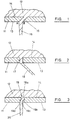
- a spinneret plate 11 supports the bottom of a body 12 of molten thermoplastics material thereon and the spinneret plate 11 presents an external face 13, which is exposed to atmosphere and in the illustrated examples is arranged to be substantially horizontal, and an internal face 14 exposed to the body 12 and upon which the body 12 rests.
- the spinneret plate 11 has a hole 15 formed therethrough and in the example the hole 15 is inclined at an angle of 45 degrees to the external face 13 of the spinneret plate 11.
- a filament 16 of the thermoplastics material is extruded through the inclined hole 15 and is tensioned substantially at right angles to the plane of the surface 13 by a filament drawing arrangement (not shown).
- the filament 16 Because the filament 16 is subjected to the rapid change of direction on leaving the hole 15, and due to the axial tension applied at an angle of 45 degrees to the axis of the filament formed in the hole 15, the filament 16 has differential stresses formed therein and which stresses cause the filament 16 to adopt a substantial degree of helical crimp when the filament 16 is allowed to relax.
- a hole 17 through the spinneret plate is substantially at right angles to the plane of the surface 13 but in this example the filament 18 is drawn off at an angle of some 45 degrees to the plane of the surface 13.
- a filament extrusion hole 19 in the spinneret plate 11 is formed by two cylindrical holes formed in opposite faces of the spinneret plate 11, with their axes substantially parallel but one axis offset from the other axis, and with the holes overlapping to form the hole 19 passing through the spinneret plate.
- the plastics material 12 flowing into the hole 19 a and subsequently hole 19 c is subjected to a great deal of turbulence, caused by the upwardly facing crescent shaped ledge 19 b and the downwardly facing crescent shaped ledge 19 d within the hole 19, and whilst the filament 20 is being formed.
- a hole 21 through the spinneret plate 11, and from which the filament 22 is extruded is again formed in two parts, the part 21 a in the surface 14 and the hole 21 b , of smaller diameter which opens to the surface 13 of the spinneret plate 11.
- the hole 21 b is fully exposed to the hole 21 a but, being of smaller diameter, forms a crescent shaped ledge 21 c between the holes 21 b and 21 a .
- the thermoplastics material flowing to form the filament 22 is subjected to substantial turbulence as the filament 22 is formed.
- the spinneret plate 11 can be formed to have a filament extrusion hole 23 formed by two holes of different diameter.
- the spinneret plate 11 is formed by two elements, 11 a and 11 b , a first hole 23 a is formed in the element 11 b , a second hole 23 b is formed in the element 11 a , the hole 23 b has a smaller diameter than the hole 12 a , and the elements 11 a and 11 b are so assembled that the hole 23 b is fully opened to the hole 23 a .
- the hole 23 b being of smaller diameter than hole 23 a , allows the element 11 a to present a crescent shaped ledge 23 c in the flow path through the hole 23.
- the ledge 23 c generates substantial turbulence in the flowable plastics material immediately before, and during, formation of the filament 24.
- the filaments 16, 18, 20, 22 and 24 may be formed in respective holes, 15, 17, 19, 21 and 23 having a non-circular cross-section and Fig. 6 (which shows a cross-section of a filament) illustrates one example of such a cross-section, comprises a full-circular cross-section with one quarter of the circle removed.
- Fig. 6 which shows a cross-section of a filament
- the points A and B of the filament 25, illustrated in Fig. 6 may be disposed close to the points A and B as illustrated by Fig. 1.
- the non-circular cross-section filaments 25, as illustrated in Fig. 6 may be subjected to a rapid differential cooling, which will again increase the crimp formed in the filaments.
- polypropylene changes from a molten state to the solid state, it does so in two stages.
- the polymer first of all passes through the "glass transition” stage. At this stage the polymer is amorphous. Stresses in the polymer in the glass transition state will self-anneal if maintained at the glass transition temperature, but at a much slower rate than in the molten state.
- the rate of cooling in a stream of gas (air) is not dependent on air temperature alone but also on the "wind chill” effect due to velocity. It is therefore possible to affect the degree of crimp in the final product by using quench air at variable velocity with constant temperature, or vice-versa, providing always the filament is cooled to the crystalline state before the internal stresses have dissipated.
- a preferred method of cooling the filaments is by subjecting the molten filaments emerging from the spinneret to a stream of "cold steam".
- Cold steam can be produced by passing water into an ultra-sonic whistle energised by compressed air.
- the "cold steam” comprises minute particles of water which rapidly evaporate on contact with the filaments. The latent heat of vaporisation produces a very pronounced reduction in temperature.
- This method of cooling is particularly advantageous because it only requires to have a flow of "cold steam" with minimal velocity so that the filaments are not vibrated or caused to flutter. This is a problem associated with using air at high velocity, and results in adjacent filaments touching and bonding together.
- a spinneret plate was drilled with 3454 holes of cross-sectional shape as shown in Figure 6, each hole having a diameter of 0.8mm. The holes were drilled in a 1:1 staggered pattern of 22 rows x 79 columns and 22 rows x 78 columns in the spinneret plate.
- the spinneret plate was fitted to a 65mm extruder which was connected to a staple fibre extrusion line.
- the extruder was charged with a narrow molecular weight polypropylene polymer sold by the Shell Chemical Co under the grade no. PLZ987.
- the extruder and spinneret were heated electrically, a temperature gradient of 196°C to 215°C was set on the extruder, and the spinneret maintained at a temperature of 210°C.
- the spinneret and die head of the extruder were positioned so that the filaments were extruded horizontally.
- the freshly formed filaments were chilled by directing a blast of cooling air so as to freeze into the filaments the differential stress and turbulence built into them by the shape of the holes in the spinneret.
- the air temperature was maintained at 14°C and to give additional cooling, the filaments were passed around 1/3 of the circumference of a non-rotating segmented cooling roller which was situated 110mm from the spinneret face.
- the roller was of 180mm diameter and was filled with circulating refrigerated water maintained at a temperature of 5°C. After passing around this refrigerated roller, the filament tow passed through an air heated crystallisation oven and then to two sets of godet rollers of the staple fibre line.
- the speed of the first godet rollers was adjusted to 25 metres per minute, and the second godet rollers to a speed of 75 metres per minute so that the filament tow was subjected to a stretching ration of 3:1.
- a hot stretching device was situated so that the polypropylene filaments were in contact with this plate during the drawing process.
- the plate was maintained at a temperature of 100°C, and the speed of the extruder was so adjusted that the throughput of polymer gave filaments, after the stretching step, which were 16.66 dtex (15 denier) per filament (i.e. 9000 metres of a single filament weighed 15 grammes).
- the filament tow was lubricated with spin finish oils and then passed to a drum cutter where the filament tow was cut to staple fibre of 100mm length.
- a batch of fibre which had been made in the manner described above was placed in a heat setting oven for a period of three minutes.
- the oven was maintained at a temperature of 130°C, and the heat set fibre was then removed and again examined and compared to the non-heat set fibres.
- the heat set fibres had shrunk in length by 10% and the helical crimp frequency had increased and the fibre was even more resilient.
- Example 1 was repeated, but the drawing speed was increased to 95 metres per minute with a draw ratio of 3:1, and the extruder speed adjusted to produce drawn filaments with a denier of 13.33 dtex (12 denier). On allowing the fibre to relax free of tension, the fibres spontaneously formed into tight helical crimps. On heat setting, the fibre was even more resilient.
- Example 2 was repeated with the exception that the output of the extruder was reduced so that the final denier of the fibre was 6.66 dtex (6 denier) per filament. On allowing the fibre to relax free of tension, the fibres spontaneously formed into tight helical crimps. On heat setting, the fibre was even more resilient.
- Example 1 was repeated with the exception that the spinneret was replaced by one drilled with the same number and layout of holes except that the hole cross-section was circular rather than as shown in Figure 6.
- the holes were arranged in the normal manner as would be carried out by a person skilled in the art of extruding synthetic filaments.
- the circular cross-section would produce the minimum of turbulence in the polymer flow immediately prior to, or at the point of, formation of the filaments.
- the fibre extrusion line and extruder were operated exactly in the manner of example 1 and 16.66 dtex (15 denier) filaments was produced. When these filaments were cut into staple lengths of 100mm and all tensions released, they did not crimp into a helical form but remained generally straight with only a slight undulation.
- the fibres remained unchanged even after heat setting and were not highly resilient.
- Example 4 was repeated using the same spinneret as in example 4 with round holes, but with the exception that the filaments were deflected from a horizontal path by lowering the cooling contact roller so that the angle of the filaments was 45 P from the horizontal. When these filaments were cut into 100mm staple lengths, they formed into a helical crimp.
- Example 1 was repeated with the exception that the spinneret was replaced with one having the same number of holes laid out in exactly the same pattern and of the same cross-sectional shape as shown in Figure 6, but the holes were drilled at an angle of 45° to the horizontal as shown in Figure 1. Fibres with a dtex of 16.5, 13.2, 11, 8.8, 6.6, 5.5, 4.4 were prepared using the extrusion conditions and godet speeds as previously described.
- the fibres were prepared using this angle of drilling of 46° had a higher degree of helical crimp when compared to the same cross-sectional shape of fibre but where the holes in the spinneret were drilled at 90°.
Landscapes
- Engineering & Computer Science (AREA)
- Physics & Mathematics (AREA)
- Fluid Mechanics (AREA)
- Textile Engineering (AREA)
- Mechanical Engineering (AREA)
- Spinning Methods And Devices For Manufacturing Artificial Fibers (AREA)
- Yarns And Mechanical Finishing Of Yarns Or Ropes (AREA)
- Preliminary Treatment Of Fibers (AREA)
- Nonwoven Fabrics (AREA)
Claims (11)
- Verfahren zur Herstellung einer im Wesentlichen spiralförmigen Kräuselung in Endlosfilamenten (16, 18, 20, 22, 24, 25), wobei geschmolzenes thermoplastisches Material (12) durch Löcher (15, 17, 19, 21, 23) in einer Spinndüsenplatte (11) zu den Filamenten stranggepresst wird und anschließend, wenn sich das thermoplastische Material der Filamente in der Kristallphase befindet, die stranggepressten Filamente reduziert werden, indem sie einem Streckschritt unterzogen werden, dadurch gekennzeichnet, dass vor der oder unmittelbar zum Zeitpunkt der Filamentbildung eine Turbulenz in dem thermoplastischen Material erzeugt wird, während es sich in seiner Glasumwandlungsphase befindet, und die durch die genannte Turbulenz induzierten Spannungen in den Filamenten aufrechterhalten werden, während die Filamente in die Kristallphase übergehen.
- Verfahren nach Anspruch 1, wobei die Turbulenz in Richtung auf eine Seite des Querschnitts der Filamente konzentriert ist.
- Verfahren nach Anspruch 1 oder 2, wobei die geschmolzenen Filamente schnell auf Verfestigung abgekühlt werden.
- Verfahren nach einem der vorherigen Ansprüche, ferner umfassend den Schritt des Strangpressens der Filamente durch Löcher in einer Spinndüsenplatte, wobei jedes Loch (15, 17) einen Winkel zu einer Außenfläche (13) der Spinndüsenplatte (11) bildet.
- Verfahren nach Anspruch 4, wobei jedes Loch (15, 17) einen Winkel von im Wesentlichen 45 Grad zur Fläche (13) der Spinndüsenplatte bildet.
- Verfahren nach einem der vorherigen Ansprüche, wobei die Turbulenz im geschmolzenen Kunststoff durch eine Veränderung (19a, 19b; 21a, 21b; 23a, 23b) des Querschnittsbereichs jedes Lochs durch die Spinndüsenplatte (11) erzeugt wird.
- Verfahren nach Anspruch 6, wobei die Veränderung des Querschnittsbereichs jedes Lochs durch die Spinndüsenplatte in der Form einer Stufe (19b, 21c, 23c) erfolgt.
- Verfahren nach einem der vorherigen Ansprüche, wobei jedes genannte Filament einen nicht kreisförmigen Querschnittsbereich (25) hat.
- Verfahren nach Anspruch 8, wobei der nicht kreisförmige Querschnittsbereich jedes Filaments durch den Querschnitt eines Lochs in einer Spinndüsenplatte (11) induziert wird.
- Verfahren nach Anspruch 8 oder 9, wobei jedes Loch in der Spinndüsenplatte eine Querschnittsgestalt (25) hat, die im Allgemeinen einem vollkreisförmigen Querschnitt entspricht, wobei im Wesentlichen ein Viertel des Kreises entfernt ist.
- Spinndüsenplatte (11) zur Herstellung einer im Wesentlichen spiralförmigen Kräuselung in Endlosfilamenten (16, 18, 20, 22, 24, 25), die Löcher (15, 17, 19, 21, 23) aufweist, durch die thermoplastisches Material (12) stranggepresst wird, um die Filamente herzustellen, dadurch gekennzeichnet, dass jedes der genannten Löcher (25) eine Querschnittsgestalt hat, die im Allgemeinen einem vollkreisförmigen Querschnitt entspricht, wobei im Wesentlichen ein Viertel des Kreises entfernt ist.
Applications Claiming Priority (3)
| Application Number | Priority Date | Filing Date | Title |
|---|---|---|---|
| GBGB9521040.7A GB9521040D0 (en) | 1995-10-13 | 1995-10-13 | Method and apparatus for producing crimped thermoplastics filaments |
| GB9521040 | 1995-10-13 | ||
| PCT/GB1996/002512 WO1997013898A1 (en) | 1995-10-13 | 1996-10-09 | Method and apparatus for producing crimped thermoplastics filaments |
Publications (2)
| Publication Number | Publication Date |
|---|---|
| EP0854943A1 EP0854943A1 (de) | 1998-07-29 |
| EP0854943B1 true EP0854943B1 (de) | 2001-12-12 |
Family
ID=10782292
Family Applications (1)
| Application Number | Title | Priority Date | Filing Date |
|---|---|---|---|
| EP96934989A Expired - Lifetime EP0854943B1 (de) | 1995-10-13 | 1996-10-09 | Verfahren und vorrichtung zur herstellung eines gekräuselten filamentgarns |
Country Status (12)
| Country | Link |
|---|---|
| US (1) | US6123886A (de) |
| EP (1) | EP0854943B1 (de) |
| JP (1) | JP2000509442A (de) |
| CN (1) | CN1084808C (de) |
| AT (1) | ATE210750T1 (de) |
| AU (1) | AU7309896A (de) |
| CA (1) | CA2234260C (de) |
| DE (1) | DE69617979T2 (de) |
| DK (1) | DK0854943T3 (de) |
| GB (1) | GB9521040D0 (de) |
| TR (1) | TR199800659T2 (de) |
| WO (1) | WO1997013898A1 (de) |
Cited By (1)
| Publication number | Priority date | Publication date | Assignee | Title |
|---|---|---|---|---|
| DE102006017553B3 (de) * | 2006-04-13 | 2007-12-27 | Eurofilters N.V. | Filterbeutel für einen Staubsauger |
Families Citing this family (13)
| Publication number | Priority date | Publication date | Assignee | Title |
|---|---|---|---|---|
| GB9918376D0 (en) * | 1999-08-05 | 1999-10-06 | Slack Philip T | Filament production method |
| US6446691B1 (en) | 2000-12-21 | 2002-09-10 | Kimberly-Clark Worldwide, Inc. | Dual capillary spinneret for production of homofilament crimp fibers |
| US6619947B2 (en) | 2000-12-21 | 2003-09-16 | Kimberly-Clark Worldwide, Inc. | Dual capillary spinneret with single outlet for production of homofilament crimp fibers |
| US6632386B2 (en) | 2000-12-22 | 2003-10-14 | Kimberly-Clark Worldwide, Inc. | In-line heat treatment of homofilament crimp fibers |
| US20020098762A1 (en) * | 2000-12-22 | 2002-07-25 | Shelley Jeffrey David | Shaped capillary production of homofilament crimp fibers |
| US7025914B2 (en) | 2000-12-22 | 2006-04-11 | Kimberly-Clark Worldwide, Inc. | Multilayer approach to producing homofilament crimp spunbond |
| US20030104748A1 (en) * | 2001-12-03 | 2003-06-05 | Brown Kurtis Lee | Helically crimped, shaped, single polymer fibers and articles made therefrom |
| US7242320B2 (en) * | 2002-05-24 | 2007-07-10 | Donnelly Mirrors Limited | Modular rearview mirror assembly |
| KR100786196B1 (ko) * | 2002-08-29 | 2007-12-17 | 주식회사 코오롱 | 사이드 바이 사이드형 복합방사 구금 |
| US20040063369A1 (en) * | 2002-09-30 | 2004-04-01 | Jung Yeul Ahn | Nonwoven loop material and process and products relating thereto |
| DE102005059214B4 (de) | 2005-12-12 | 2007-10-25 | Eurofilters N.V. | Filterbeutel für einen Staubsauger |
| US20090197080A1 (en) * | 2008-01-31 | 2009-08-06 | Glew Charles A | Self-crimping fluoropolymer and perfluoropolymer filaments and fibers |
| CN103541025A (zh) * | 2013-09-26 | 2014-01-29 | 吴江伊莱纺织科技有限公司 | 一种喷丝板 |
Citations (1)
| Publication number | Priority date | Publication date | Assignee | Title |
|---|---|---|---|---|
| EP0006743A2 (de) * | 1978-06-26 | 1980-01-09 | Monsanto Company | Spinn-Texturierverfahren |
Family Cites Families (4)
| Publication number | Priority date | Publication date | Assignee | Title |
|---|---|---|---|---|
| US3092873A (en) * | 1958-10-17 | 1963-06-11 | Celanese Corp | Spinneret |
| GB1126552A (en) * | 1965-06-04 | 1968-09-05 | Fiber Industries Inc | Improvements in the production of crimped staple fibre |
| US3781949A (en) * | 1972-05-03 | 1974-01-01 | Du Pont | Process and apparatus for jet-texturing yarn at high speed |
| US5531951A (en) * | 1993-11-22 | 1996-07-02 | Wellman, Inc. | Method of forming staple fibers from self-texturing filaments |
-
1995
- 1995-10-13 GB GBGB9521040.7A patent/GB9521040D0/en active Pending
-
1996
- 1996-10-09 EP EP96934989A patent/EP0854943B1/de not_active Expired - Lifetime
- 1996-10-09 DK DK96934989T patent/DK0854943T3/da active
- 1996-10-09 DE DE69617979T patent/DE69617979T2/de not_active Expired - Fee Related
- 1996-10-09 CA CA002234260A patent/CA2234260C/en not_active Expired - Fee Related
- 1996-10-09 WO PCT/GB1996/002512 patent/WO1997013898A1/en not_active Ceased
- 1996-10-09 AT AT96934989T patent/ATE210750T1/de not_active IP Right Cessation
- 1996-10-09 AU AU73098/96A patent/AU7309896A/en not_active Abandoned
- 1996-10-09 CN CN96197585A patent/CN1084808C/zh not_active Expired - Fee Related
- 1996-10-09 US US09/051,614 patent/US6123886A/en not_active Expired - Fee Related
- 1996-10-09 TR TR1998/00659T patent/TR199800659T2/xx unknown
- 1996-10-09 JP JP9514841A patent/JP2000509442A/ja active Pending
Patent Citations (1)
| Publication number | Priority date | Publication date | Assignee | Title |
|---|---|---|---|---|
| EP0006743A2 (de) * | 1978-06-26 | 1980-01-09 | Monsanto Company | Spinn-Texturierverfahren |
Cited By (1)
| Publication number | Priority date | Publication date | Assignee | Title |
|---|---|---|---|---|
| DE102006017553B3 (de) * | 2006-04-13 | 2007-12-27 | Eurofilters N.V. | Filterbeutel für einen Staubsauger |
Also Published As
| Publication number | Publication date |
|---|---|
| GB9521040D0 (en) | 1995-12-13 |
| DK0854943T3 (da) | 2002-04-15 |
| TR199800659T2 (xx) | 1998-07-21 |
| CA2234260C (en) | 2005-09-13 |
| ATE210750T1 (de) | 2001-12-15 |
| CN1199432A (zh) | 1998-11-18 |
| DE69617979T2 (de) | 2002-08-22 |
| EP0854943A1 (de) | 1998-07-29 |
| US6123886A (en) | 2000-09-26 |
| CN1084808C (zh) | 2002-05-15 |
| WO1997013898A1 (en) | 1997-04-17 |
| DE69617979D1 (de) | 2002-01-24 |
| AU7309896A (en) | 1997-04-30 |
| CA2234260A1 (en) | 1997-04-17 |
| JP2000509442A (ja) | 2000-07-25 |
Similar Documents
| Publication | Publication Date | Title |
|---|---|---|
| US6123886A (en) | Method and apparatus for producing crimped thermoplastics | |
| US20070231519A1 (en) | Method and Apparatus for High Denier Hollow Spiral Fiber | |
| US4687610A (en) | Low crystallinity polyester yarn produced at ultra high spinning speeds | |
| US5730821A (en) | Process for producing a web of thermoplastic polymer filaments | |
| JP2003503604A (ja) | 本質的に連続的である細い糸を製造するための方法及びデバイス | |
| US5059104A (en) | Melt spinning apparatus | |
| CN101305118A (zh) | 用于制造三维卷曲的皮芯短纤维的方法和这种皮芯短纤维 | |
| EP1090170A1 (de) | Spinnvorrichtung zum spinnen eines synthetischen fadens | |
| US6824717B2 (en) | Method for melt spinning filament yarns | |
| US4461740A (en) | Process for spin-stretching of high strength technical yarns | |
| US5310514A (en) | Process and spinning device for making microfilaments | |
| US3693851A (en) | Method for fibrillating stretched film | |
| US3979496A (en) | Method of imparting latent crimp in polyolefin synthetic fibers | |
| US3457338A (en) | Process for crimping polypropylene filaments | |
| US7850899B2 (en) | Method of making spun-bond web from multicomponent filaments | |
| CA1206713A (en) | Melt-spinning polyester filaments | |
| US5643515A (en) | Method and apparatus for producing stretched yarns | |
| KR950008902B1 (ko) | 멀티필라멘트의 제조방법 및 장치 | |
| US4605364A (en) | Melt-spinning apparatus for polyester filaments | |
| CN117737873B (zh) | 一种同板异孔异径吸湿排汗仿毛纤维的生产方法及专用设备 | |
| JP2000178824A (ja) | モノフィラメント捲縮糸の製造方法および製造装置 | |
| US3768938A (en) | Textile process and apparatus | |
| GB2105641A (en) | Manufacture of filamentary polymer tow | |
| JPH01207437A (ja) | 合成繊維の延伸方法 | |
| WO1998045512A1 (en) | Crimped solid thermoplastic filaments |
Legal Events
| Date | Code | Title | Description |
|---|---|---|---|
| PUAI | Public reference made under article 153(3) epc to a published international application that has entered the european phase |
Free format text: ORIGINAL CODE: 0009012 |
|
| 17P | Request for examination filed |
Effective date: 19980507 |
|
| AK | Designated contracting states |
Kind code of ref document: A1 Designated state(s): AT BE CH DE DK ES FI FR GB GR IE IT LI LU MC NL PT SE |
|
| 17Q | First examination report despatched |
Effective date: 19981218 |
|
| GRAG | Despatch of communication of intention to grant |
Free format text: ORIGINAL CODE: EPIDOS AGRA |
|
| GRAG | Despatch of communication of intention to grant |
Free format text: ORIGINAL CODE: EPIDOS AGRA |
|
| GRAH | Despatch of communication of intention to grant a patent |
Free format text: ORIGINAL CODE: EPIDOS IGRA |
|
| GRAH | Despatch of communication of intention to grant a patent |
Free format text: ORIGINAL CODE: EPIDOS IGRA |
|
| GRAA | (expected) grant |
Free format text: ORIGINAL CODE: 0009210 |
|
| AK | Designated contracting states |
Kind code of ref document: B1 Designated state(s): AT BE CH DE DK ES FI FR GB GR IE IT LI LU MC NL PT SE |
|
| PG25 | Lapsed in a contracting state [announced via postgrant information from national office to epo] |
Ref country code: NL Free format text: LAPSE BECAUSE OF FAILURE TO SUBMIT A TRANSLATION OF THE DESCRIPTION OR TO PAY THE FEE WITHIN THE PRESCRIBED TIME-LIMIT Effective date: 20011212 Ref country code: LI Free format text: LAPSE BECAUSE OF FAILURE TO SUBMIT A TRANSLATION OF THE DESCRIPTION OR TO PAY THE FEE WITHIN THE PRESCRIBED TIME-LIMIT Effective date: 20011212 Ref country code: GR Free format text: LAPSE BECAUSE OF FAILURE TO SUBMIT A TRANSLATION OF THE DESCRIPTION OR TO PAY THE FEE WITHIN THE PRESCRIBED TIME-LIMIT Effective date: 20011212 Ref country code: FR Free format text: LAPSE BECAUSE OF FAILURE TO SUBMIT A TRANSLATION OF THE DESCRIPTION OR TO PAY THE FEE WITHIN THE PRESCRIBED TIME-LIMIT Effective date: 20011212 Ref country code: FI Free format text: LAPSE BECAUSE OF FAILURE TO SUBMIT A TRANSLATION OF THE DESCRIPTION OR TO PAY THE FEE WITHIN THE PRESCRIBED TIME-LIMIT Effective date: 20011212 Ref country code: CH Free format text: LAPSE BECAUSE OF FAILURE TO SUBMIT A TRANSLATION OF THE DESCRIPTION OR TO PAY THE FEE WITHIN THE PRESCRIBED TIME-LIMIT Effective date: 20011212 Ref country code: AT Free format text: LAPSE BECAUSE OF FAILURE TO SUBMIT A TRANSLATION OF THE DESCRIPTION OR TO PAY THE FEE WITHIN THE PRESCRIBED TIME-LIMIT Effective date: 20011212 |
|
| REF | Corresponds to: |
Ref document number: 210750 Country of ref document: AT Date of ref document: 20011215 Kind code of ref document: T |
|
| REG | Reference to a national code |
Ref country code: CH Ref legal event code: EP |
|
| REG | Reference to a national code |
Ref country code: GB Ref legal event code: IF02 |
|
| REG | Reference to a national code |
Ref country code: IE Ref legal event code: FG4D |
|
| REF | Corresponds to: |
Ref document number: 69617979 Country of ref document: DE Date of ref document: 20020124 |
|
| PG25 | Lapsed in a contracting state [announced via postgrant information from national office to epo] |
Ref country code: SE Free format text: LAPSE BECAUSE OF FAILURE TO SUBMIT A TRANSLATION OF THE DESCRIPTION OR TO PAY THE FEE WITHIN THE PRESCRIBED TIME-LIMIT Effective date: 20020312 Ref country code: PT Free format text: LAPSE BECAUSE OF FAILURE TO SUBMIT A TRANSLATION OF THE DESCRIPTION OR TO PAY THE FEE WITHIN THE PRESCRIBED TIME-LIMIT Effective date: 20020312 |
|
| REG | Reference to a national code |
Ref country code: DK Ref legal event code: T3 |
|
| NLV1 | Nl: lapsed or annulled due to failure to fulfill the requirements of art. 29p and 29m of the patents act | ||
| REG | Reference to a national code |
Ref country code: CH Ref legal event code: PL |
|
| PG25 | Lapsed in a contracting state [announced via postgrant information from national office to epo] |
Ref country code: ES Free format text: LAPSE BECAUSE OF FAILURE TO SUBMIT A TRANSLATION OF THE DESCRIPTION OR TO PAY THE FEE WITHIN THE PRESCRIBED TIME-LIMIT Effective date: 20020627 |
|
| PG25 | Lapsed in a contracting state [announced via postgrant information from national office to epo] |
Ref country code: LU Free format text: LAPSE BECAUSE OF NON-PAYMENT OF DUE FEES Effective date: 20021009 Ref country code: IE Free format text: LAPSE BECAUSE OF NON-PAYMENT OF DUE FEES Effective date: 20021009 |
|
| EN | Fr: translation not filed | ||
| PLBE | No opposition filed within time limit |
Free format text: ORIGINAL CODE: 0009261 |
|
| STAA | Information on the status of an ep patent application or granted ep patent |
Free format text: STATUS: NO OPPOSITION FILED WITHIN TIME LIMIT |
|
| 26N | No opposition filed | ||
| PG25 | Lapsed in a contracting state [announced via postgrant information from national office to epo] |
Ref country code: MC Free format text: LAPSE BECAUSE OF NON-PAYMENT OF DUE FEES Effective date: 20030501 |
|
| NLV1 | Nl: lapsed or annulled due to failure to fulfill the requirements of art. 29p and 29m of the patents act | ||
| REG | Reference to a national code |
Ref country code: IE Ref legal event code: MM4A |
|
| PGFP | Annual fee paid to national office [announced via postgrant information from national office to epo] |
Ref country code: GB Payment date: 20061003 Year of fee payment: 11 |
|
| PGFP | Annual fee paid to national office [announced via postgrant information from national office to epo] |
Ref country code: DE Payment date: 20061006 Year of fee payment: 11 |
|
| PGFP | Annual fee paid to national office [announced via postgrant information from national office to epo] |
Ref country code: BE Payment date: 20061013 Year of fee payment: 11 |
|
| PGFP | Annual fee paid to national office [announced via postgrant information from national office to epo] |
Ref country code: DK Payment date: 20061016 Year of fee payment: 11 |
|
| PGFP | Annual fee paid to national office [announced via postgrant information from national office to epo] |
Ref country code: IT Payment date: 20061031 Year of fee payment: 11 |
|
| BERE | Be: lapsed |
Owner name: *SCS CONSULTANCY SERVICES Effective date: 20071031 |
|
| REG | Reference to a national code |
Ref country code: DK Ref legal event code: EBP |
|
| GBPC | Gb: european patent ceased through non-payment of renewal fee |
Effective date: 20071009 |
|
| PG25 | Lapsed in a contracting state [announced via postgrant information from national office to epo] |
Ref country code: DE Free format text: LAPSE BECAUSE OF NON-PAYMENT OF DUE FEES Effective date: 20080501 |
|
| PG25 | Lapsed in a contracting state [announced via postgrant information from national office to epo] |
Ref country code: BE Free format text: LAPSE BECAUSE OF NON-PAYMENT OF DUE FEES Effective date: 20071031 |
|
| PG25 | Lapsed in a contracting state [announced via postgrant information from national office to epo] |
Ref country code: DK Free format text: LAPSE BECAUSE OF NON-PAYMENT OF DUE FEES Effective date: 20071031 |
|
| PG25 | Lapsed in a contracting state [announced via postgrant information from national office to epo] |
Ref country code: GB Free format text: LAPSE BECAUSE OF NON-PAYMENT OF DUE FEES Effective date: 20071009 |
|
| PG25 | Lapsed in a contracting state [announced via postgrant information from national office to epo] |
Ref country code: IT Free format text: LAPSE BECAUSE OF NON-PAYMENT OF DUE FEES Effective date: 20071009 |