EP0854997B1 - Zusammengesetzter dichtring und konstruktion mit einem solchen dichtring - Google Patents
Zusammengesetzter dichtring und konstruktion mit einem solchen dichtring Download PDFInfo
- Publication number
- EP0854997B1 EP0854997B1 EP96937366A EP96937366A EP0854997B1 EP 0854997 B1 EP0854997 B1 EP 0854997B1 EP 96937366 A EP96937366 A EP 96937366A EP 96937366 A EP96937366 A EP 96937366A EP 0854997 B1 EP0854997 B1 EP 0854997B1
- Authority
- EP
- European Patent Office
- Prior art keywords
- ring
- gasket
- tube
- connector
- bushing
- Prior art date
- Legal status (The legal status is an assumption and is not a legal conclusion. Google has not performed a legal analysis and makes no representation as to the accuracy of the status listed.)
- Expired - Lifetime
Links
Images


Classifications
-
- G—PHYSICS
- G02—OPTICS
- G02B—OPTICAL ELEMENTS, SYSTEMS OR APPARATUS
- G02B5/00—Optical elements other than lenses
- G02B5/30—Polarising elements
- G02B5/3025—Polarisers, i.e. arrangements capable of producing a definite output polarisation state from an unpolarised input state
- G02B5/3033—Polarisers, i.e. arrangements capable of producing a definite output polarisation state from an unpolarised input state in the form of a thin sheet or foil, e.g. Polaroid
-
- F—MECHANICAL ENGINEERING; LIGHTING; HEATING; WEAPONS; BLASTING
- F16—ENGINEERING ELEMENTS AND UNITS; GENERAL MEASURES FOR PRODUCING AND MAINTAINING EFFECTIVE FUNCTIONING OF MACHINES OR INSTALLATIONS; THERMAL INSULATION IN GENERAL
- F16L—PIPES; JOINTS OR FITTINGS FOR PIPES; SUPPORTS FOR PIPES, CABLES OR PROTECTIVE TUBING; MEANS FOR THERMAL INSULATION IN GENERAL
- F16L41/00—Branching pipes; Joining pipes to walls
- F16L41/08—Joining pipes to walls or pipes, the joined pipe axis being perpendicular to the plane of a wall or to the axis of another pipe
- F16L41/086—Joining pipes to walls or pipes, the joined pipe axis being perpendicular to the plane of a wall or to the axis of another pipe fixed with screws
-
- B—PERFORMING OPERATIONS; TRANSPORTING
- B29—WORKING OF PLASTICS; WORKING OF SUBSTANCES IN A PLASTIC STATE IN GENERAL
- B29C—SHAPING OR JOINING OF PLASTICS; SHAPING OF MATERIAL IN A PLASTIC STATE, NOT OTHERWISE PROVIDED FOR; AFTER-TREATMENT OF THE SHAPED PRODUCTS, e.g. REPAIRING
- B29C55/00—Shaping by stretching, e.g. drawing through a die; Apparatus therefor
- B29C55/02—Shaping by stretching, e.g. drawing through a die; Apparatus therefor of plates or sheets
- B29C55/023—Shaping by stretching, e.g. drawing through a die; Apparatus therefor of plates or sheets using multilayered plates or sheets
-
- B—PERFORMING OPERATIONS; TRANSPORTING
- B29—WORKING OF PLASTICS; WORKING OF SUBSTANCES IN A PLASTIC STATE IN GENERAL
- B29C—SHAPING OR JOINING OF PLASTICS; SHAPING OF MATERIAL IN A PLASTIC STATE, NOT OTHERWISE PROVIDED FOR; AFTER-TREATMENT OF THE SHAPED PRODUCTS, e.g. REPAIRING
- B29C55/00—Shaping by stretching, e.g. drawing through a die; Apparatus therefor
- B29C55/02—Shaping by stretching, e.g. drawing through a die; Apparatus therefor of plates or sheets
- B29C55/04—Shaping by stretching, e.g. drawing through a die; Apparatus therefor of plates or sheets uniaxial, e.g. oblique
-
- B—PERFORMING OPERATIONS; TRANSPORTING
- B29—WORKING OF PLASTICS; WORKING OF SUBSTANCES IN A PLASTIC STATE IN GENERAL
- B29C—SHAPING OR JOINING OF PLASTICS; SHAPING OF MATERIAL IN A PLASTIC STATE, NOT OTHERWISE PROVIDED FOR; AFTER-TREATMENT OF THE SHAPED PRODUCTS, e.g. REPAIRING
- B29C55/00—Shaping by stretching, e.g. drawing through a die; Apparatus therefor
- B29C55/02—Shaping by stretching, e.g. drawing through a die; Apparatus therefor of plates or sheets
- B29C55/10—Shaping by stretching, e.g. drawing through a die; Apparatus therefor of plates or sheets multiaxial
- B29C55/12—Shaping by stretching, e.g. drawing through a die; Apparatus therefor of plates or sheets multiaxial biaxial
- B29C55/14—Shaping by stretching, e.g. drawing through a die; Apparatus therefor of plates or sheets multiaxial biaxial successively
-
- B—PERFORMING OPERATIONS; TRANSPORTING
- B60—VEHICLES IN GENERAL
- B60H—ARRANGEMENTS OF HEATING, COOLING, VENTILATING OR OTHER AIR-TREATING DEVICES SPECIALLY ADAPTED FOR PASSENGER OR GOODS SPACES OF VEHICLES
- B60H1/00—Heating, cooling or ventilating devices
- B60H1/00507—Details, e.g. mounting arrangements, desaeration devices
- B60H1/00557—Details of ducts or cables
- B60H1/00571—Details of ducts or cables of liquid ducts, e.g. for coolant liquids or refrigerants
-
- F—MECHANICAL ENGINEERING; LIGHTING; HEATING; WEAPONS; BLASTING
- F16—ENGINEERING ELEMENTS AND UNITS; GENERAL MEASURES FOR PRODUCING AND MAINTAINING EFFECTIVE FUNCTIONING OF MACHINES OR INSTALLATIONS; THERMAL INSULATION IN GENERAL
- F16L—PIPES; JOINTS OR FITTINGS FOR PIPES; SUPPORTS FOR PIPES, CABLES OR PROTECTIVE TUBING; MEANS FOR THERMAL INSULATION IN GENERAL
- F16L37/00—Couplings of the quick-acting type
- F16L37/02—Couplings of the quick-acting type in which the connection is maintained only by friction of the parts being joined
- F16L37/025—Couplings of the quick-acting type in which the connection is maintained only by friction of the parts being joined with an inner elastic part pressed against an outer part by reason of its elasticity
-
- G—PHYSICS
- G02—OPTICS
- G02B—OPTICAL ELEMENTS, SYSTEMS OR APPARATUS
- G02B5/00—Optical elements other than lenses
- G02B5/30—Polarising elements
- G02B5/3008—Polarising elements comprising dielectric particles, e.g. birefringent crystals embedded in a matrix
-
- B—PERFORMING OPERATIONS; TRANSPORTING
- B29—WORKING OF PLASTICS; WORKING OF SUBSTANCES IN A PLASTIC STATE IN GENERAL
- B29K—INDEXING SCHEME ASSOCIATED WITH SUBCLASSES B29B, B29C OR B29D, RELATING TO MOULDING MATERIALS OR TO MATERIALS FOR MOULDS, REINFORCEMENTS, FILLERS OR PREFORMED PARTS, e.g. INSERTS
- B29K2995/00—Properties of moulding materials, reinforcements, fillers, preformed parts or moulds
- B29K2995/0018—Properties of moulding materials, reinforcements, fillers, preformed parts or moulds having particular optical properties, e.g. fluorescent or phosphorescent
-
- Y—GENERAL TAGGING OF NEW TECHNOLOGICAL DEVELOPMENTS; GENERAL TAGGING OF CROSS-SECTIONAL TECHNOLOGIES SPANNING OVER SEVERAL SECTIONS OF THE IPC; TECHNICAL SUBJECTS COVERED BY FORMER USPC CROSS-REFERENCE ART COLLECTIONS [XRACs] AND DIGESTS
- Y10—TECHNICAL SUBJECTS COVERED BY FORMER USPC
- Y10S—TECHNICAL SUBJECTS COVERED BY FORMER USPC CROSS-REFERENCE ART COLLECTIONS [XRACs] AND DIGESTS
- Y10S285/00—Pipe joints or couplings
- Y10S285/918—O-ring
Definitions
- the present invention relates to a seal composite seal arranged to be threaded at friction on a rigid tube end suitable to be inserted in a room with a connection hole with the end piece, the seal comprising at least one ring made of elastomeric material.
- Such a connection can for example be of the type removable and / or snap-on.
- connection joints waterproof and / or removable connections between a pipe end and a mechanical part.
- the prior art essentially teaches o-rings inserted in grooves of the tubular nozzle whose external diameter does not allow not always an insertion without play in the opening of connection, and taking into account the tolerance ratings for machining parts.
- the present invention aims to provide a seal responding better than those previously known to requirements of the practice, particularly in that it allows a simple assembly, easy to implement, which does not generate a risk of damage to the seal by the fitter, in that it guarantees a connection optimized between the nozzle and the orifice and this with a tolerance of the dimensions much better than that obtained in the prior art, which ensures a better sealing of the connection.
- the present invention provides in particular a composite seal according to the claim 1.
- the invention also provides a part / tube assembly comprising a composite joint of the type described above. It also offers a part / tube assembly with composite seal of the type described above, characterized in that the rigid tube end piece has a first part projecting from the external face of the tube, said first part being located at a distance. from the end of the tube, and a second projecting part located at the end of said tube, said projecting parts forming longitudinal locking stops on either side of the joint on the tube end piece.
- the invention also provides a set part / tube comprising a composite joint as described above, characterized in that the end piece comprises at minus an annular groove into which is inserted at at least partially the ring made of elastomeric material.
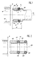
- Figure 1 shows a composite gasket 1 rubbed on a tip 2 of rigid tube, for example aluminum, suitable for insertion into a part 3 provided with a cylindrical orifice or bore 4 for connection with the nozzle 2.
- the seal has a ring of elastomeric material for example a rubber O-ring 5.
- the composite seal 1 further comprises a ring 6 rigid material; for example steel or rigid plastic, sleeve-shaped cylindrical, i.e. higher than its thickness, between 1.5 and 5 times said thickness, for example of the order of 2 times or 3. times higher, located next to and in the longitudinal extension of the ring which is, at free state, thicker than the thickness of the sleeve.
- a ring 6 rigid material for example steel or rigid plastic, sleeve-shaped cylindrical, i.e. higher than its thickness, between 1.5 and 5 times said thickness, for example of the order of 2 times or 3. times higher, located next to and in the longitudinal extension of the ring which is, at free state, thicker than the thickness of the sleeve.
- the end of the ring 6 is for example of shape partially annular, or more generally of shape complementary to that of ring 5 for partly conform to the shape of the edge of said ring.
- the face of connection between ring and ring is for example straight, i.e. perpendicular to the axis of the ring.
- the ring is permanently fixed to the ring 5 for example by gluing, overmolding or vulcanization during the manufacture of the seal, in the longitudinal extension of the ring.
- the ring 6 has an internal surface 7 cylindrical cooperating in soft friction, with the external surface 8 of the tube end piece and an external surface 9 suitable for cooperate with gentle friction with the internal face 10 of the connection hole.
- soft friction means respect for dimension tolerances between the bore and the ring arranged so that the distance between their two facing surfaces is between 0.05 mm and 0.22 mm.
- the axes of the ring in the shape of an O-ring 5 and of the ring 6 are merged with the axis 11 of the tube on the end of which the composite seal 1 is threaded.
- the elastomeric material can also and by example be an elastomer with butyl chain or HNBR.
- the ring extends by example on either side of the internal faces 7 and outer 9 of the ring or is substantially tangent to the longitudinal extension of the internal face 7 of the ring, and protrudes in the free state, for example a few tenths of a millimeter, relative to the outer face 9 of the ring 6.
- the ring can be a ring in aluminum, steel, galvanized steel or other rigid material (plastic for example) with an adjustment tolerance of type H7g6 with the bore for example of nominal diameter 12 mm; 15.3 mm; 18.23mm or 21.4mm; the tube end being for example and meanwhile of external diameter 8.5 mm; 11.7 mm; 14.7mm or 17.8mm.
- the part / tube assembly is for example such that the end piece 2 of rigid tube is metallic (it can also be in other type of material, for rigid plastic example) and has a first part projecting 12 relative to the face outer 8 of the tube, for example obtained by folding the wall of the tube.
- the projection is located at a distance d from the end 13 of the tube, d being greater than the total height (longitudinal dimension) of the composite joint, for example a few millimeters, for example 2 mm.
- the tip also includes a second part 14 protruding, located at the end 13 of the tube, obtained for example by widening the latter on a thickness less than that of the ring 6.
- the projecting parts 12 and 14 form annular or conical blocking stops longitudinal on either side of the joint on the end piece of tube, of maximum diameter less than the diameter ring 6.
- the tube is fixed on part 3 by through a plate (not shown) rendered integral with the nozzle and fixed to the part by example via bolts or any other known fixing means (not shown).
- Figure 2 shows a seal 15 comprising a first ring 16 whose end 17 cylinder-shaped is secured to a first O-ring 18 moreover attached, on the other hand, to a second ring 19, itself comprising at its other end 20 a second seal 21 made of elastomeric material, the rings and the joints being of identical axis 22, the diameter seals 18 and 21 being greater than the thickness of the rings 16 and 19.
- the rings 16 and 19 are for example of dimensions identical.
- One of the rings can also be smaller dimension than the other, for example have a height equal to 2/3 the height of the other ring.
- Figure 3 shows a part / tube assembly 23 comprising a seal 15 according to FIG. 2 provided with annular rings 16 and 19 whose internal faces cooperate with gentle friction by having a shape internal 24 complementary to external form 25 of aluminum tube 26 on which they are threaded with rings 18 and 20.
- the seal 15 is not fixed longitudinally for allow a slight sliding on the tube on one side, but is nevertheless blocked in its course on one side by a fold 27 and on the other side by a part in projection 28.
- the cylindrical external faces of the rings 16 and 17 co-operate with friction with the internal face 29 of the cylindrical bore 30 of the part 31.
- a fixing plate 32 fixed to the tip of the tube 26 by folds 27 and 33 on either side of flat external faces of the plate 32 allows the fixing of the tube integral with the plate on the face external plane 34 of the part, for example by a cross bolt 35 screwed into a bore 36 of said piece.
- the invention also relates to the modes of realization where the ring of elastomer material is not not an O-ring but is a seal with minus a cut-off surface, for example a joint of octagonal section, and / or is a profile joint special, those where the composite joint has three rings of elastomeric material or more, and / or three rings of rigid material or more.
- Profile seal special is for example a seal 37 (cf. figure 4) fitted with a cylindrical ring 38 made of metal or rigid material and a ring of elastic material in the form of an elongated 8, or elongated dumbbells comprising two toric end portions 39 and a portion 40 of elongated, cylindrical junction, parallel to the axis of the joint.
- Figures 5 and 6 show another mode of production of a seal 41 according to the invention.
- the seal 41 includes a ring 42 of material elastomer formed in part by a double seal toric substantially 8-shaped elongated parallel to the axis 43 of the joint
- the ring 42 has the same side of the joint with respect to axis 43, two lines or sealing or pressure surfaces, respectively, 44 and 45, located two by two in the same plane cylindrical with axis 43 and formed by the parts swollen from 8.
- Said ring 42 is arranged to cooperate in a part with the outer face of the nozzle and on the other hand with the internal face of the part.
- the ring 42 also comprises a part end 46 into portions 47 of low cylinder thickness arranged angularly, for example six lamellar portions parallel to, and located on the side of, the axis 43 being part of a annular cylinder and connected by one end 48 to the underside 49 of the 8-shaped portion of the ring with which they are united.
- the seal 41 also includes a ring 50 in rigid material, in the form of a cylindrical sleeve, type described with reference to FIG. 1, and of which the end 51 of junction with the part in the form of 8 of the ring is for example straight.
- the outer surface 52 of the ring is arranged to cooperate with gentle friction with the internal face 53 (See FIG. 7) of a bore drilled in part 54, and its internal face 55 cooperates with the external faces 56 of the portions 47 in the form of strips, the internal faces 57 themselves cooperate in friction with the tip 58 of the tube.
- the portions 47 form slats extending for example over the entire height of the ring 50 and according to arcs of a circle included between 5 ° and 50 °, for example 10 °.
- the angular distribution of the portions 47 is symmetrical, and varies according to the number of. portions which can be between two and twenty, for example three, four, six or eight.
- the thickness of the lamellar portions 47 is for example between 0.3 mm and 2 mm, for example of 0.5 mm.
- FIG. 7 a set part / tube comprising part 54 provided with an orifice 59 formed by the cylindrical bore on the inside 53, and a screw fixing orifice 60 with a flange 61.
- the assembly includes a tube 62 integral with the flange, provided with the end piece 58 on the end of which is simply frictionally threaded the seal 41 described in reference to Figures 5 and 6.
- the outer end 63 of the shaped part 8 elongated abuts on a protrusion 64 of the flange, the end 65 of the ring coming as to it level the terminal edge 66 of the end of the tube.
- Figure 8 shows another embodiment of a nozzle according to the invention with seal 68, of the type described with reference to Figure 5, but reversed from 180 ° from its layout described in reference to figure 7.
- the end piece 67 comprises a abutment flange 69, a cylindrical zone 70 in extra thickness of 1 to 3 tenths of a millimeter, arranged to cooperate in force with the end of the ring 50 covered internally by the lamellae seal elastomer, and the end cap itself arranged to cooperate with the end 71 at 8 elongated of ring 42, entirely located on the side of the end of the nozzle.
- the end of the rigid ring is in abutment on the flange 69.
- Figures 9, 10 and 11 show three other joint embodiments according to the invention, provided with end portions different.
- Figures 9, 10 show a joint 72, 73 with ring 74, 75 respectively provided with a portion of annular end 76, 77 comprising a part in projection 78, 79, of triangular section 78, rounded or rectangular 79 able to cooperate with a groove internal annular, 80 formed in the external face from the mouthpiece.
- Figure 11 shows a joint 81 with protuberance internal 82, annular, in the lower part of the ring 83, over a shorter distance (for example 1 / 10th, 1/4 or 1/3), or equal to the height ring 84, and suitable for detachably locking the seal on the nozzle.
Landscapes
- Engineering & Computer Science (AREA)
- Mechanical Engineering (AREA)
- General Engineering & Computer Science (AREA)
- Physics & Mathematics (AREA)
- Thermal Sciences (AREA)
- General Physics & Mathematics (AREA)
- Optics & Photonics (AREA)
- Crystallography & Structural Chemistry (AREA)
- Chemical & Material Sciences (AREA)
- Gasket Seals (AREA)
- Joints With Sleeves (AREA)
- Quick-Acting Or Multi-Walled Pipe Joints (AREA)
- Sealing Material Composition (AREA)
- Non-Disconnectible Joints And Screw-Threaded Joints (AREA)
- Shaping By String And By Release Of Stress In Plastics And The Like (AREA)
- Polarising Elements (AREA)
- Laminated Bodies (AREA)
Claims (13)
- Zusammengesetzte Dichtungsverbindung (1, 15, 41) für den Ansatz (2, 58) eines starren Rohres zum Einschieben in ein Teil (3, 54) mit einer Öffnung (1, 4, 59) in Form einer zylinderförmigen Bohrung zum Anschluss des Ansatzes, mit wenigstens einem Ring (5, 18, 21, 42) aus einem Elastomermaterial und wenigstens einer Buchse (6, 16, 19, 50) aus starrem Material, das mit dem Ring (5, 18, 21, 42) aus einem Elastomermaterial aus einem Stück besteht, wobei die Buchse eine Ringform hat und in der Verlängerung des Ringes parallel zu und koaxial mit der Achse des Ringes liegt, und die Verbindung unter Reibung auf den Ansatz aufgeschoben wird und das Ende der Verbindung (17, 52) eine komplementäre Form zu der des Ringes hat, um sich wenigstens teilweise an die Querschnittsform des Ringes anzupassen,
dadurch gekennzeichnet, dass die Buchse mit ihrer Außenfläche (9, 52) mit leichter Reibung mit der Innenfläche (10, 53) der Anschlussöffnung zusammenwirkt,
dass die Buchse die Form einer zylinderförmigen Muffe mit einer Höhe zwischen den 1,5-fachen und dem 5-fachen ihrer Dicke aufweist, die Innenfläche (7) mit leichter Reibung direkt oder über ein Endteil (46) des Ringes mit der Außenfläche (8) des Ansatzes zusammenwirkt,
und dass der Ring oder einer der Ringe (42) aus einem elastischen Material einen Querschnitt mit im wesentlichen der Form einer verlängerten 8 aufweist. - Verbindung (15) nach Anspruch 1,
dadurch gekennzeichnet, dass sie zwei Ringe (18, 21) aus einem Elastomermaterial enthält, die zu beiden Seiten der Buchse (19) liegen. - Verbindung (15) nach einem der vorangehenden Ansprüche,
dadurch gekennzeichnet, dass sie zwei Buchsen (16, 19) aus einem starren Material enthält. - Verbindung nach Anspruch 2 und 3,
dadurch gekennzeichnet, dass die Buchsen (16, 19) über einen der Ringe (18) aus Elastomermaterial miteinander verbunden sind, mit dem sie aus einem Stück bestehen, und
dass wenigstens eine der Buchsen (19) die andere Dichtung (21) aus Elastomer an ihrem anderen Ende (20) enthält. - Verbindung nach einem der vorangehenden Ansprüche,
dadurch gekennzeichnet, dass ein Ring ein O-Ring ist. - Verbindung nach einem der vorangehenden Ansprüche,
dadurch gekennzeichnet, dass der Ring aus elastischem Material mit der Form einer verlängerten 8 einen Querschnitt in der Form einer Hantel mit zwei wulstförmigen Endteilen 39 und einem Teil 40 zur Verbindung des verlängerten Zylinders aufweist. - Verbindung nach einem der vorangehenden Ansprüche,
dadurch gekennzeichnet, dass der Ring (42) ein Endteil(46) aus Zylinderabschnitten enthält, die winkelmäßig um die Achse der Verbindung angeordnet sind und mit der Innenfläche der Buchse zusammenwirken. - Verbindung nach Anspruch 7,
dadurch gekennzeichnet, dass die Lamellen bildenden Teile (47) sich über die ganze Höhe der Buchse und über Kreisbögen zwischen 5° und 50° erstrecken, die gleichmäßig verteilt sind. - Verbindung nach einem der Ansprüche 1 bis 6,
dadurch gekennzeichnet, dass der Ring (74, 75) ein ringförmiges Endteil (76, 77) aufweist, das mit einem vorspringenden Teil (78, 79) mit einem dreieckförmigen (78), einem abgerundeten oder rechteckigen (79) Querschnitt versehen ist, der mit einer ringförmigen Nut (80) auf der Außenseite der Buchse zusammenwirkt. - Anordnung aus Teil/Rohr mit einer Verbindung gemäß einem der vorangehenden Ansprüche.
- Anordnung aus Teil/Rohr (2, 3) nach Anspruch 10,
dadurch gekennzeichnet, dass der Ansatz (2) des starren Rohres einen ersten Teil (12) enthält, der über die Außenfläche (8) des Rohres hinausragt und bei einem Abstand d von dem Ende (13) des Rohres liegt, und dass ein zweiter Teil (14), der über die Außenfläche (8) des Rohres hinausragt, bei dem Ende (13) des Rohres liegt, und dass die hinausragenden Teile (12, 14) Anschläge in Längsrichtung zu beiden Seiten der Dichtung auf dem Rohransatz bilden. - Anordnung aus Teil/Rohr nach Anspruch 10,
dadurch gekennzeichnet, dass der Ansatz wenigstens eine ringförmige Nut enthält, in die wenigstens ein Teil des Rings aus Elastomermaterial eingreift. - Anordnung aus Teil/Rohr nach Anspruch 10,
dadurch gekennzeichnet, dass der Ansatz (67) einen Anschlagflansch (69) enthält und mit dem Ende (71) des Rings (42) zusammenwirkt, der vollständig auf der Seite des Endes des Ansatzes liegt.
Priority Applications (1)
| Application Number | Priority Date | Filing Date | Title |
|---|---|---|---|
| EP99125962A EP0997679A1 (de) | 1995-10-30 | 1996-10-30 | Zusammengesetzte Dichtung und Anordnung mit Anwendung einer solchen Dichtung |
Applications Claiming Priority (3)
| Application Number | Priority Date | Filing Date | Title |
|---|---|---|---|
| FR9512797 | 1995-10-30 | ||
| FR9512797A FR2740526B1 (fr) | 1995-10-30 | 1995-10-30 | Joint d'etancheite composite pour raccordement etanche entre une extremite de tube et une piece, et ensemble piece/tube comportant un tel joint |
| PCT/FR1996/001705 WO1997016670A1 (fr) | 1995-10-30 | 1996-10-30 | Joint d'etancheite composite, et ensemble comportant un tel joint |
Related Child Applications (1)
| Application Number | Title | Priority Date | Filing Date |
|---|---|---|---|
| EP99125962A Division EP0997679A1 (de) | 1995-10-30 | 1996-10-30 | Zusammengesetzte Dichtung und Anordnung mit Anwendung einer solchen Dichtung |
Publications (2)
| Publication Number | Publication Date |
|---|---|
| EP0854997A1 EP0854997A1 (de) | 1998-07-29 |
| EP0854997B1 true EP0854997B1 (de) | 2002-07-24 |
Family
ID=9484059
Family Applications (2)
| Application Number | Title | Priority Date | Filing Date |
|---|---|---|---|
| EP96937366A Expired - Lifetime EP0854997B1 (de) | 1995-10-30 | 1996-10-30 | Zusammengesetzter dichtring und konstruktion mit einem solchen dichtring |
| EP99125962A Withdrawn EP0997679A1 (de) | 1995-10-30 | 1996-10-30 | Zusammengesetzte Dichtung und Anordnung mit Anwendung einer solchen Dichtung |
Family Applications After (1)
| Application Number | Title | Priority Date | Filing Date |
|---|---|---|---|
| EP99125962A Withdrawn EP0997679A1 (de) | 1995-10-30 | 1996-10-30 | Zusammengesetzte Dichtung und Anordnung mit Anwendung einer solchen Dichtung |
Country Status (9)
| Country | Link |
|---|---|
| US (1) | US6260851B1 (de) |
| EP (2) | EP0854997B1 (de) |
| JP (1) | JP2000509465A (de) |
| KR (1) | KR100639744B1 (de) |
| AT (1) | ATE221171T1 (de) |
| BR (1) | BR9611301A (de) |
| DE (2) | DE69622573T2 (de) |
| FR (1) | FR2740526B1 (de) |
| WO (1) | WO1997016670A1 (de) |
Cited By (3)
| Publication number | Priority date | Publication date | Assignee | Title |
|---|---|---|---|---|
| FR2924778A1 (fr) * | 2007-12-10 | 2009-06-12 | Joint Francais | Piece d'etancheite pour embout de tube et ensemble le comportant |
| EP2458251A1 (de) | 2010-11-25 | 2012-05-30 | Coes Company Srl | Verbundstoffgleitbuchse für Hochdruckanschlussstücke |
| WO2013160919A1 (en) | 2012-04-24 | 2013-10-31 | Coes Company Srl | A composite sliding gasket for high-pressure joints |
Families Citing this family (57)
| Publication number | Priority date | Publication date | Assignee | Title |
|---|---|---|---|---|
| FR2790303B1 (fr) | 1999-02-26 | 2001-05-04 | Hutchinson | Dispositif d'etancheite pour raccordement etanche entre un tube rigide et un element de connexion femelle dans un circuit de transfert de fluide, et raccord equipe d'un tel dispositif |
| US6443502B1 (en) * | 1999-04-22 | 2002-09-03 | Denso Corporation | Leakage restriction device for refrigeration cycle |
| FR2795155B1 (fr) | 1999-06-17 | 2001-08-10 | Hutchinson | Dispositif de raccord etanche pour conduit de fluide, en particulier pour vehicule automobile |
| DE19949880B4 (de) * | 1999-10-15 | 2007-02-22 | Georg Fischer Rohrleitungssysteme Ag | Anordnung zum Abdichten von Rohrleitungen |
| JP3724360B2 (ja) * | 1999-11-09 | 2005-12-07 | 東海ゴム工業株式会社 | コネクタ |
| FR2807134B1 (fr) * | 2000-03-31 | 2002-05-31 | Legris Sa | Dispositif d'etancheite et organe de raccordement d'une extremite de conduite a un element d'un circuit de transport de fluides |
| US7407165B1 (en) | 2000-04-04 | 2008-08-05 | Hutchinson Fts, Inc. | Composite sleeve for sealing a tubular coupling |
| JP2002317764A (ja) * | 2001-04-20 | 2002-10-31 | Toyota Industries Corp | 圧縮機のシール構造及び圧縮機 |
| US7140618B2 (en) * | 2003-01-16 | 2006-11-28 | Vassallo Research & Development Corporation | Socket with dual-functional composite gasket |
| JP4096832B2 (ja) * | 2003-07-22 | 2008-06-04 | 株式会社デンソー | 冷凍サイクル用配管継手 |
| JP4030478B2 (ja) * | 2003-07-29 | 2008-01-09 | 株式会社デンソー | 冷凍サイクル用配管継手 |
| DE502004008908D1 (de) * | 2003-12-22 | 2009-03-12 | Behr Gmbh & Co Kg | Dichtungsanordnung, insbesondere für einen Anschluss einer Leitung an einem Expansionsorgan |
| ITMI20040816A1 (it) * | 2004-04-26 | 2004-07-26 | Guala Closures Spa | Struttura di raccordo ad innesto rapido per tubazioni di impianti di climatizzazione refrigerazione e simili |
| US20060022458A1 (en) * | 2004-07-27 | 2006-02-02 | Timothy Droste | Sealed fluid connector assembly |
| FR2873782B1 (fr) * | 2004-07-30 | 2008-03-14 | Manuli Auto France Sa | Raccord etanche a double joints et bague de protection |
| JP5025076B2 (ja) * | 2004-09-24 | 2012-09-12 | ニッタ株式会社 | 樹脂管の接続構造 |
| US7448653B2 (en) | 2005-06-10 | 2008-11-11 | Value Plastics, Inc. | Female connector for releasable coupling with a male connector defining a fluid conduit |
| US7806139B2 (en) | 2006-01-20 | 2010-10-05 | Value Plastics, Inc. | Fluid conduit coupling assembly having male and female couplers with integral valves |
| US7621568B2 (en) * | 2006-04-25 | 2009-11-24 | Visteon Global Technologies, Inc. | Block fitting and seal structure |
| WO2008077013A2 (en) * | 2006-12-18 | 2008-06-26 | Parker-Hannifin Corporation | Connection of tubes for air conditioning and seal adapted thereto |
| DE102007003606A1 (de) * | 2007-01-18 | 2008-07-31 | Mci Gmbh & Co. Kg | Dichtungsanordnung für ein Gehäuse |
| AT504504B1 (de) * | 2007-04-27 | 2008-06-15 | Vaillant Austria Gmbh | Gasdichte verbindung |
| USD654573S1 (en) | 2007-11-19 | 2012-02-21 | Value Plastics, Inc. | Female quick connect fitting |
| US8235426B2 (en) | 2008-07-03 | 2012-08-07 | Nordson Corporation | Latch assembly for joining two conduits |
| JP5402340B2 (ja) * | 2008-08-28 | 2014-01-29 | 豊田合成株式会社 | 配管の接続構造体 |
| US20110227295A1 (en) * | 2008-11-25 | 2011-09-22 | Nok Corporation | Two-material composite gasket |
| US8982462B2 (en) * | 2008-12-22 | 2015-03-17 | 3M Innovative Properties Company | Multilayer optical films having side-by-side mirror/polarizer zones |
| FR2947021B1 (fr) * | 2009-06-22 | 2011-07-15 | Mann & Hummel Gmbh | Dispositif de maintien d'un joint d'etancheite annulaire sur un troncon tubulaire |
| USD655393S1 (en) | 2009-06-23 | 2012-03-06 | Value Plastics, Inc. | Multi-port valve |
| US9388929B2 (en) | 2009-12-09 | 2016-07-12 | Nordson Corporation | Male bayonet connector |
| USD783815S1 (en) | 2009-12-09 | 2017-04-11 | General Electric Company | Male dual lumen bayonet connector |
| USD650478S1 (en) | 2009-12-23 | 2011-12-13 | Value Plastics, Inc. | Female dual lumen connector |
| US10711930B2 (en) | 2009-12-09 | 2020-07-14 | Nordson Corporation | Releasable connection assembly |
| USD649240S1 (en) | 2009-12-09 | 2011-11-22 | Value Plastics, Inc. | Male dual lumen bayonet connector |
| CN102753876B (zh) | 2009-12-23 | 2015-07-22 | 诺信公司 | 具有一体式模制悬臂弹簧的按钮闩 |
| EP2516913B1 (de) | 2009-12-23 | 2014-09-17 | Nordson Corporation | Fluidverbinderverriegelungen mit profildurchführungen |
| USD652511S1 (en) | 2011-02-11 | 2012-01-17 | Value Plastics, Inc. | Female body of connector for fluid tubing |
| USD663022S1 (en) | 2011-02-11 | 2012-07-03 | Nordson Corporation | Male body of connector for fluid tubing |
| USD652510S1 (en) | 2011-02-11 | 2012-01-17 | Value Plastics, Inc. | Connector for fluid tubing |
| US8967245B2 (en) * | 2011-05-24 | 2015-03-03 | Baker Hughes Incorporated | Borehole seal, backup and method |
| JP5464171B2 (ja) * | 2011-05-25 | 2014-04-09 | 株式会社デンソー | 流体通路接続装置 |
| USD699840S1 (en) | 2011-07-29 | 2014-02-18 | Nordson Corporation | Male body of connector for fluid tubing |
| USD698440S1 (en) | 2011-07-29 | 2014-01-28 | Nordson Corporation | Connector for fluid tubing |
| USD699841S1 (en) | 2011-07-29 | 2014-02-18 | Nordson Corporation | Female body of connector for fluid tubing |
| USD709612S1 (en) | 2011-12-23 | 2014-07-22 | Nordson Corporation | Female dual lumen connector |
| GB2503880B (en) * | 2012-07-09 | 2019-03-13 | Polypipe Ltd | Insert for pipes |
| DK2846069T3 (en) * | 2013-09-05 | 2018-01-15 | Definox Sas | LOCK VALVE WITH FLOAT SEAL |
| US9360140B2 (en) * | 2013-12-10 | 2016-06-07 | GM Global Technology Operations LLC | Sealing device for a vehicle |
| US9903496B2 (en) * | 2015-05-29 | 2018-02-27 | Mueller International, Llc | Lining for mechanical joints |
| US9383050B1 (en) * | 2015-10-22 | 2016-07-05 | Grand Hall Enterprise Co., Ltd. | Quick removal plumbing fitting |
| US10794524B2 (en) * | 2016-09-06 | 2020-10-06 | Keith R. Bunn, SR. | Pipe coupling assembly |
| USD838366S1 (en) | 2016-10-31 | 2019-01-15 | Nordson Corporation | Blood pressure connector |
| DE102017112829A1 (de) * | 2017-06-12 | 2018-12-13 | Schaeffler Technologies AG & Co. KG | Konnektoranordnung |
| CN113124160A (zh) * | 2021-04-26 | 2021-07-16 | 中国船舶重工集团公司第七0三研究所 | 外部受压组合垫圈 |
| DE102021127568A1 (de) | 2021-10-22 | 2023-04-27 | Zf Active Safety Gmbh | Verbindungsvorrichtung für einen dichten Austausch von Fluid zwischen zwei Bauteilen, Verbindungssystem und Bremssystem |
| DE102023213238A1 (de) * | 2023-12-21 | 2025-06-26 | Volkswagen Aktiengesellschaft | Dichtungsanordnung zum Abdichten einer strömungsführenden Verbindung, elektrischer Antrieb mit Dichtungsanordnung und Kraftfahrzeug mit Dichtungsanordnung |
| CN221943475U (zh) * | 2024-03-20 | 2024-11-01 | 日丰企业(佛山)有限公司 | 钢塑复合管道用的连接装置和钢塑复合连接管道 |
Family Cites Families (21)
| Publication number | Priority date | Publication date | Assignee | Title |
|---|---|---|---|---|
| DE7104371U (de) * | Junkers & Co Gmbh | |||
| US1976589A (en) * | 1933-04-20 | 1934-10-09 | Lock Joint Pipe Co | Pipe joint |
| DE644601C (de) * | 1935-01-24 | 1937-05-08 | Buderus Eisenwerk | Muffenrohrverbindung mit buchsenartigem Dichtungskoerper |
| US3061321A (en) * | 1957-07-15 | 1962-10-30 | Parker Hannifin Corp | Double contact fluid seal |
| US3325174A (en) * | 1964-11-16 | 1967-06-13 | Woodward Iron Company | Pipe joint packing |
| FR1551816A (de) * | 1967-01-25 | 1968-12-27 | ||
| US3834744A (en) * | 1972-06-19 | 1974-09-10 | Garlock Inc | Pipe coupling |
| FR2328899A1 (fr) * | 1975-10-06 | 1977-05-20 | Sabla Sa | Joint pour le raccordement etanche de tuyaux en beton |
| GB1494669A (en) * | 1976-07-01 | 1977-12-07 | Rolls Royce | Pipe joints |
| DE2824476C2 (de) * | 1978-06-03 | 1983-03-17 | Bayerische Motoren Werke AG, 8000 München | Brennstoffeinspritzdüsenbefestigung an einer Brennkraftmaschine |
| US4915136A (en) * | 1980-10-29 | 1990-04-10 | Proprietary Technology, Inc. | Stuffer plug quick connector assembly |
| US4799512A (en) * | 1987-11-12 | 1989-01-24 | Tuthill Corporation | Coupling assembly |
| DE8807990U1 (de) * | 1988-06-16 | 1988-08-18 | Joh. Vaillant Gmbh U. Co, 5630 Remscheid | Rohrförmige Steuerleitung |
| US4946206A (en) * | 1989-02-27 | 1990-08-07 | Prinsco, Inc. | Bidirectional corrugated pipe-rib seal |
| US5486949A (en) * | 1989-06-20 | 1996-01-23 | The Dow Chemical Company | Birefringent interference polarizer |
| US5171028A (en) * | 1990-01-16 | 1992-12-15 | Proprietary Technology, Inc. | Snap and lock quick connector |
| JPH0552284A (ja) * | 1991-08-20 | 1993-03-02 | Usui Internatl Ind Co Ltd | 細径配管接続用コネクター |
| US5423577A (en) * | 1992-01-17 | 1995-06-13 | Bundy Corporation | Tubing connector |
| EP0566889B1 (de) * | 1992-03-25 | 1997-07-09 | Tokai Rubber Industries, Ltd. | Schnellkupplung |
| US5609370A (en) * | 1994-12-02 | 1997-03-11 | Itt Corporation | Positive latch quick connector |
| DE19504186C2 (de) * | 1995-02-09 | 1999-04-15 | Mannesmann Rexroth Ag | Axialdichtung |
-
1995
- 1995-10-30 FR FR9512797A patent/FR2740526B1/fr not_active Expired - Fee Related
-
1996
- 1996-10-30 DE DE69622573T patent/DE69622573T2/de not_active Expired - Lifetime
- 1996-10-30 BR BR9611301-4A patent/BR9611301A/pt not_active IP Right Cessation
- 1996-10-30 EP EP96937366A patent/EP0854997B1/de not_active Expired - Lifetime
- 1996-10-30 EP EP99125962A patent/EP0997679A1/de not_active Withdrawn
- 1996-10-30 WO PCT/FR1996/001705 patent/WO1997016670A1/fr not_active Ceased
- 1996-10-30 US US09/066,455 patent/US6260851B1/en not_active Expired - Fee Related
- 1996-10-30 JP JP9517116A patent/JP2000509465A/ja active Pending
- 1996-10-30 DE DE29680972U patent/DE29680972U1/de not_active Expired - Lifetime
- 1996-10-30 AT AT96937366T patent/ATE221171T1/de not_active IP Right Cessation
-
1998
- 1998-12-10 KR KR1020007007701A patent/KR100639744B1/ko not_active Expired - Fee Related
Cited By (3)
| Publication number | Priority date | Publication date | Assignee | Title |
|---|---|---|---|---|
| FR2924778A1 (fr) * | 2007-12-10 | 2009-06-12 | Joint Francais | Piece d'etancheite pour embout de tube et ensemble le comportant |
| EP2458251A1 (de) | 2010-11-25 | 2012-05-30 | Coes Company Srl | Verbundstoffgleitbuchse für Hochdruckanschlussstücke |
| WO2013160919A1 (en) | 2012-04-24 | 2013-10-31 | Coes Company Srl | A composite sliding gasket for high-pressure joints |
Also Published As
| Publication number | Publication date |
|---|---|
| DE69622573T2 (de) | 2003-03-27 |
| ATE221171T1 (de) | 2002-08-15 |
| FR2740526B1 (fr) | 1998-01-16 |
| DE69622573D1 (de) | 2002-08-29 |
| KR100639744B1 (ko) | 2006-10-31 |
| WO1997016670A1 (fr) | 1997-05-09 |
| EP0854997A1 (de) | 1998-07-29 |
| DE29680972U1 (de) | 1998-11-05 |
| BR9611301A (pt) | 1999-12-28 |
| FR2740526A1 (fr) | 1997-04-30 |
| EP0997679A1 (de) | 2000-05-03 |
| KR20010034091A (ko) | 2001-04-25 |
| JP2000509465A (ja) | 2000-07-25 |
| US6260851B1 (en) | 2001-07-17 |
Similar Documents
| Publication | Publication Date | Title |
|---|---|---|
| EP0854997B1 (de) | Zusammengesetzter dichtring und konstruktion mit einem solchen dichtring | |
| EP0840867B1 (de) | Vorrichtung zum dichten verbinden eines starren rohrendstückes mit einem schlauch und herstellungsverfahren für eine solche vorrichtung | |
| FR2648894A2 (fr) | Perfectionnements a une pince pour dispositif de raccordement instantane de conduit de fluide, et dispositifs pourvus d'une telle pince | |
| EP1497582B1 (de) | Undurchlässige verbindungsvorrichtung, insbesondere für das motorlufteinlasssystem eines kraftfahrzeugs | |
| FR2766547A1 (fr) | Conduit flexible, par exemple tuyau a usage medical ou chirurgical | |
| EP0458700B1 (de) | Abgedichtete Verbindung zweier stumpf aneinanderstossender glatter Rohre | |
| EP0751335B1 (de) | Dichte Verbindung mit radialem Einsteckende | |
| FR2528533A1 (fr) | Raccord traversant a ecrou tournant pour gaine exterieurement spiralee | |
| FR2691511A1 (fr) | Dispositif d'assemblage rapide d'un ensemble d'organes tubulaires à des embouts. | |
| EP1075619B1 (de) | Dichtung und rohrverbindung mit einer solchen vorrichtung | |
| EP1303730B1 (de) | Entspannungsvorrichtung für kühlmittel und eine solche vorrichtung enthaltender kühlkreislauf | |
| FR2822519A1 (fr) | Raccord pour tuyau | |
| EP0593325A1 (de) | Verbindung für einen Dichtring | |
| FR2696523A1 (fr) | Corps creux, notamment soufflet de protection pour la tige de piston d'un amortisseur. | |
| FR2767181A1 (fr) | Dispositif de raccordement rapide d'un tube a un element rigide | |
| FR2727494A1 (fr) | Joint a profil special pour raccordement etanche entre une extremite de tube et une piece | |
| FR2727493A1 (fr) | Dispositif et procede de raccordement etanche entre une bride munie d'au moins un tube et une piece | |
| FR2721368A1 (fr) | Joint d'étanchéité. | |
| FR2660406A1 (fr) | Raccord de tube a brides fendues. | |
| EP2402144B1 (de) | Anschlussvorrichtung und -verfahren, insbesondere für Wasserkühlkreislauf in einem Kraftfahrzeug | |
| WO1997016673A1 (fr) | Raccord etanche a connexion rapide | |
| FR2833665A1 (fr) | Soufflet d'etancheite et joint de transmission correspondant | |
| EP2827037A1 (de) | Rohranschlussmodul | |
| WO1998058204A1 (fr) | Dispositif de raccordement etanche entre un embout de tube metallique et l'extremite d'un tuyau souple, et procede de fabrication d'un tel dispositif | |
| FR2884577A1 (fr) | Joint annulaire pour raccord de transfert de fluide et raccord equipe d'un tel joint |
Legal Events
| Date | Code | Title | Description |
|---|---|---|---|
| PUAI | Public reference made under article 153(3) epc to a published international application that has entered the european phase |
Free format text: ORIGINAL CODE: 0009012 |
|
| 17P | Request for examination filed |
Effective date: 19980526 |
|
| AK | Designated contracting states |
Kind code of ref document: A1 Designated state(s): AT BE CH DE DK ES FI FR GB GR IE IT LI LU MC NL PT SE |
|
| 17Q | First examination report despatched |
Effective date: 20000809 |
|
| GRAG | Despatch of communication of intention to grant |
Free format text: ORIGINAL CODE: EPIDOS AGRA |
|
| GRAG | Despatch of communication of intention to grant |
Free format text: ORIGINAL CODE: EPIDOS AGRA |
|
| GRAH | Despatch of communication of intention to grant a patent |
Free format text: ORIGINAL CODE: EPIDOS IGRA |
|
| GRAH | Despatch of communication of intention to grant a patent |
Free format text: ORIGINAL CODE: EPIDOS IGRA |
|
| GRAA | (expected) grant |
Free format text: ORIGINAL CODE: 0009210 |
|
| AK | Designated contracting states |
Kind code of ref document: B1 Designated state(s): AT BE CH DE DK ES FI FR GB GR IE IT LI LU MC NL PT SE |
|
| PG25 | Lapsed in a contracting state [announced via postgrant information from national office to epo] |
Ref country code: NL Free format text: LAPSE BECAUSE OF FAILURE TO SUBMIT A TRANSLATION OF THE DESCRIPTION OR TO PAY THE FEE WITHIN THE PRESCRIBED TIME-LIMIT Effective date: 20020724 Ref country code: IE Free format text: LAPSE BECAUSE OF FAILURE TO SUBMIT A TRANSLATION OF THE DESCRIPTION OR TO PAY THE FEE WITHIN THE PRESCRIBED TIME-LIMIT Effective date: 20020724 Ref country code: GR Free format text: LAPSE BECAUSE OF FAILURE TO SUBMIT A TRANSLATION OF THE DESCRIPTION OR TO PAY THE FEE WITHIN THE PRESCRIBED TIME-LIMIT Effective date: 20020724 Ref country code: GB Free format text: LAPSE BECAUSE OF FAILURE TO SUBMIT A TRANSLATION OF THE DESCRIPTION OR TO PAY THE FEE WITHIN THE PRESCRIBED TIME-LIMIT Effective date: 20020724 Ref country code: FI Free format text: LAPSE BECAUSE OF FAILURE TO SUBMIT A TRANSLATION OF THE DESCRIPTION OR TO PAY THE FEE WITHIN THE PRESCRIBED TIME-LIMIT Effective date: 20020724 Ref country code: AT Free format text: LAPSE BECAUSE OF FAILURE TO SUBMIT A TRANSLATION OF THE DESCRIPTION OR TO PAY THE FEE WITHIN THE PRESCRIBED TIME-LIMIT Effective date: 20020724 |
|
| REF | Corresponds to: |
Ref document number: 221171 Country of ref document: AT Date of ref document: 20020815 Kind code of ref document: T |
|
| REG | Reference to a national code |
Ref country code: GB Ref legal event code: FG4D Free format text: NOT ENGLISH |
|
| REG | Reference to a national code |
Ref country code: CH Ref legal event code: EP |
|
| REG | Reference to a national code |
Ref country code: IE Ref legal event code: FG4D Free format text: FRENCH |
|
| REF | Corresponds to: |
Ref document number: 69622573 Country of ref document: DE Date of ref document: 20020829 |
|
| PG25 | Lapsed in a contracting state [announced via postgrant information from national office to epo] |
Ref country code: SE Free format text: LAPSE BECAUSE OF FAILURE TO SUBMIT A TRANSLATION OF THE DESCRIPTION OR TO PAY THE FEE WITHIN THE PRESCRIBED TIME-LIMIT Effective date: 20021024 Ref country code: PT Free format text: LAPSE BECAUSE OF FAILURE TO SUBMIT A TRANSLATION OF THE DESCRIPTION OR TO PAY THE FEE WITHIN THE PRESCRIBED TIME-LIMIT Effective date: 20021024 Ref country code: DK Free format text: LAPSE BECAUSE OF FAILURE TO SUBMIT A TRANSLATION OF THE DESCRIPTION OR TO PAY THE FEE WITHIN THE PRESCRIBED TIME-LIMIT Effective date: 20021024 |
|
| PG25 | Lapsed in a contracting state [announced via postgrant information from national office to epo] |
Ref country code: LU Free format text: LAPSE BECAUSE OF NON-PAYMENT OF DUE FEES Effective date: 20021030 |
|
| PG25 | Lapsed in a contracting state [announced via postgrant information from national office to epo] |
Ref country code: LI Free format text: LAPSE BECAUSE OF NON-PAYMENT OF DUE FEES Effective date: 20021031 Ref country code: CH Free format text: LAPSE BECAUSE OF NON-PAYMENT OF DUE FEES Effective date: 20021031 Ref country code: BE Free format text: LAPSE BECAUSE OF NON-PAYMENT OF DUE FEES Effective date: 20021031 |
|
| NLV1 | Nl: lapsed or annulled due to failure to fulfill the requirements of art. 29p and 29m of the patents act | ||
| GBV | Gb: ep patent (uk) treated as always having been void in accordance with gb section 77(7)/1977 [no translation filed] |
Effective date: 20020724 |
|
| PG25 | Lapsed in a contracting state [announced via postgrant information from national office to epo] |
Ref country code: ES Free format text: LAPSE BECAUSE OF FAILURE TO SUBMIT A TRANSLATION OF THE DESCRIPTION OR TO PAY THE FEE WITHIN THE PRESCRIBED TIME-LIMIT Effective date: 20030130 |
|
| REG | Reference to a national code |
Ref country code: IE Ref legal event code: FD4D Ref document number: 0854997E Country of ref document: IE |
|
| BERE | Be: lapsed |
Owner name: *MANULI AUTO FRANCE Effective date: 20021031 |
|
| PG25 | Lapsed in a contracting state [announced via postgrant information from national office to epo] |
Ref country code: MC Free format text: LAPSE BECAUSE OF NON-PAYMENT OF DUE FEES Effective date: 20030501 |
|
| PLBE | No opposition filed within time limit |
Free format text: ORIGINAL CODE: 0009261 |
|
| STAA | Information on the status of an ep patent application or granted ep patent |
Free format text: STATUS: NO OPPOSITION FILED WITHIN TIME LIMIT |
|
| REG | Reference to a national code |
Ref country code: CH Ref legal event code: PL |
|
| 26N | No opposition filed |
Effective date: 20030425 |
|
| PG25 | Lapsed in a contracting state [announced via postgrant information from national office to epo] |
Ref country code: IT Free format text: LAPSE BECAUSE OF NON-PAYMENT OF DUE FEES Effective date: 20051030 |
|
| PGRI | Patent reinstated in contracting state [announced from national office to epo] |
Ref country code: IT Effective date: 20110616 |
|
| REG | Reference to a national code |
Ref country code: FR Ref legal event code: PLFP Year of fee payment: 20 |
|
| PGFP | Annual fee paid to national office [announced via postgrant information from national office to epo] |
Ref country code: IT Payment date: 20151021 Year of fee payment: 20 Ref country code: DE Payment date: 20151026 Year of fee payment: 20 |
|
| PGFP | Annual fee paid to national office [announced via postgrant information from national office to epo] |
Ref country code: FR Payment date: 20151013 Year of fee payment: 20 |
|
| REG | Reference to a national code |
Ref country code: DE Ref legal event code: R071 Ref document number: 69622573 Country of ref document: DE |